I have been doing aerial photography with a variety of RC Helicopters for a few years. The biggest problem is short flight duration and pilot work load.
I have decided to design and build my own fixed wing aerial photography platform.
Here is my project goal; A fixed wing aerial photography platform with the ability to fly semi-autonomously (take off and landing pilot controlled). The camera will be mounted on a self-leveling mount to allow for photogrammetry and 3d point cloud generation, with a 10 minute minimum mission time.
A secondary goal is remotely operated camera mount that allows 360 degree pan and 90 degree tilt with a video downlink for camera aiming. FPV operation is also an option.
An ArduPilot Mega will be used as the autopilot. The ArduPilot does allow for self takeoffs and landings.
I have built, flown, crashed, and re-built RC Aircraft for many years and enjoy the hobby. This time I am designing my own airframe from the ground up. I will be honest I will borrow from other designs during the progression to my goal, in the end the airframe will be mine.
For the moment my my primary building materials will be Foam Core, Blue Core (Fan Fold) and Depron.
Comments and critisim are appreciated.
I hope you enjoy the trip
p.s. I am behind in posts here, and have flown airframe #1
DealExtreme threw some gps modules on their site today. Most of them are GlobaSat SIRF Star III modules (at least, that is what DX claims them to be, check your facts by checking the datasheets) and there is one EM-411.
Prices are in the range of US$ 14.30 - 14.90 for the GlobalSat modules and US$ 28.30 for the GlobalSat EM-411. Shipping is free (or included in the price).
All of this is open source and freely available for download. You can find the core autopilot here. We developed it using eclipse, but the environment is fully arduino compatible as well thanks to the hardwork of Mike! http://code.google.com/p/ardupilotone/ This repository is for rover specific configuration files and a wiki site for ardupilotone based rovers. http://code.google.com/p/ardurover/ To run the hardware in the loop you will need the mavsim scicoslab toolbox here. https://github.com/openmav/mavsimRead more…
A semi-autonomous civilian UAV system designed for hunters and fisherman. The current project is called The VULTURE System (Versatile Unmanned Lingering Terrain Utilization and REcon ). It will be used to help hunters and fisherman find game and schools of fish as well as to find the best areas to hunt in and paths to take.
The user will be able to unpack the system take off vertically and look at the view from the air and then circling areas of interest until the hunter, fisherman or team of eithar can reach the location. The system is not designed to be ultra portable from the ground, but more with someone dedicated to ground support at camp or on a boat to guide the team.
Key Features:
VTOL Capabilities
Long range communications
Long flight duration (<30 minutes)
Autonomous loitering abilities
Waypoint navigation and return to user in the event of not receiving transmissions
Infrared camera for finding game, schools of fish and night time recon
Initial testing of certain functions will be done on a SkyHawk powered glider
Final testing and platform will be a modified Predator pictured above
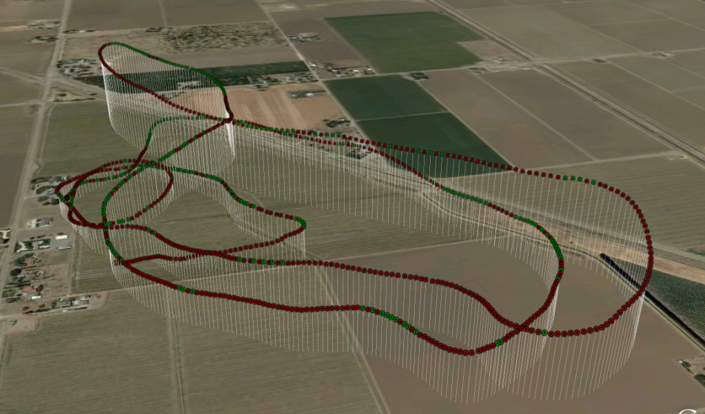
I went to the first Bay Area FPV fly-in, met some people with really nice setups. One person was using the iTelemetry app, from Immersion RC. You can see he didn't quite make it back to the field (ran out of power), which could have been a pretty serious thing since we were flying in a hayfield and the plane was totally hidden in the grass.
He was able to take his iphone out to the field, and follow on google maps directly to the pin that was documenting the plane's location. He also produced this nifty flight image, but I'm not sure if this was in the app or on his computer.
Does anyone know of a similar telemetry app in the APM world?
In this demo, Pat Hickey from Invensense does a demo on a turntable showing how much error you can expect from an IMU (in this case the MPU 3000 using the onboard Kalman filter) in a turn if you don't have a GPS or magnetometer to correct it. The answer is less than 10 degrees at .2G (12 inch turntable turning at 33rpm), which is a reasonable guess of what a plane would experience in a prolonged turn.
This is relevant because the forthcoming Invensense MPU 6000 sensor with 3-axis gyros and 3-axis acclerometers on a single chip has a great onboard sensor fusion processor, which is attractive to use. But it doesn't have an on-board magnetometer or a good way to input GPS data into the sensor fusion processing, which could correct the inertial errors from centrifugal forces.
So what if you go without that correction? This demo suggests that the consequences might not be too bad.
It's a dedicated video (PAL or NTSC) Arduino shield with passthrough capabilities. Nothing fancy, just a sync separator and some passive electronics. Obviously, it needs to be mated with an Arduino (additional one, alongside APM, of course), but it's plug and play and comes with a neatly put together library. Question is, can this + Arduino physically fit an average ArduCopter?
If so, it might be the ticket to beginner's quad computer vision experimentation (plus, you get an OSD generator extra ;) on the cheap ($50ish + camera).
Read more…Moderator
today i upload last revision of ArducopterNG32 , I upload the code after my fly test doing tomorrow.
This is the video.
With this revision of code is possible to fly in acro e stable mode.
Today i'm doing my first outdoor test of ArmFox V4 firmware in basic configuration , I'm happy of the result , the quad is flying fine and seemsreliable, even ifarevisionisalphacode.
In this test i use standard component , don't professional part.
MP32 and Oilpan work fine togheter.
I use 4 Chineese standard 18 A PWM ESC buy on Giancod store at 6$
Standard Motor 900 kv
10 inch propeller.
Standard 6 channel analog reciver on 35 Mhz.
So this is an entry level configuration.
Yesterday I spoke with Diego L. that are using only analog gyro and accelerometer connected directly to MP32 , That sensor normally is used on Aeroquad , but is the same that mount Oilpan , the only difference is that is connected by spi adc to MP32 instead on Diego configuration It is directly connected to analog input.
The MP32 analog input is better of avr analog because are at 12 bit . We notice that the configuration of analog is the same of oilpan. The resolution is the same.
The video , is only a raw fly with some test for check relability.
I need to setup the PID on gyro , today during flying there was much raffic of wind .
MP32 is next revision of CPU for Arducopter project based on 32 Bit arm microprocessor with 72 mhz of clock and a lot of innovative hardware feature as 2 i2c one for sensor , can bus , 512 kbyte flash and 64 kbyte ram. 12 bit analog input for more info visit discussion forum on www.virtualrobotix.com
Next step is testing advanced functionality on air : Gps hold ,altitude hold ecc
Some suggestions about my PID these is the standard available on Arducopter NG
P 4.0
I 0.150
D 1.20
I change also Stick_to_angle factor conversion for have more command available.
What do you think about ? In the next test i would put our VR ESC that use i2c bus and have 256 step of resolution this esc only 127 :( That's could be a problem for good fly ... :)
Well, to work in a spin stabilized mode, Marcy 2 would have to spin a lot faster than a 3 channel coaxial copter can. Without spin stabilization, a $40 Syma S107 or a $25 Sky Invader didn't matter because either way, we needed another gyro to know heading. A 150 second flight time doesn't demand a very accurate gyro.
Mass produced Marcy 2's would use the cheapest single axis gyro available, but suddenly a static proof bag of new gyros happened to fall off a truck. It's the ITG3200, another crazy small 0.5mm Invensense QFN.
Decided to go ahead with it, to evaluate it for another 3 DOF IMU. Have 5 years made
any difference with Invense gyros?
Unfortunately, it immediately showed a large dead band, a convenient solution to the same old gremlin
of gyro 0 offsets drifting. It automatically 0 centers itself, but it has to rotate a large, minimum amount to detect anything. You can rotate it slowly enough, handheld, to go 90 deg without sensing anything.
It's intended for hand held motion sensing & gesture user interfaces, not a heading hold gyro. The deadband gets a lot
bigger as the lowpass bandwidth gets lower.
Direct analog pins would make this chip a lot more useful, but obviously doing the samping on the die eliminated a lot of parts that would be required for analog pins.
Through the IDG300, ADXRS150, LISY300, & ITG3200, gyros have gotten cheaper, but
they still use the same mechanism they did 5 years ago. They can stack multiple gyros,
sample more bits, but the mechanism hasn't gotten any better.
UPDATE:
It wasn't a deadband as much as a mismatch between the lower & upper 8 bits. It took a lot of rotation to get above 0. Then the result was smooth from 0 - 255. Then, it took a lot of rotation to get above 255.
It turned out the chip doesn't work in I2C burst mode. You have to read the analog results 1 byte at a time.
MARCY 1
Read over the monocopter paper again, 2 years later, & figured out 3 factors affecting stability:
Wing pressure needs to go through the CG of the balance beam.
Coning angle needs to be minimal.
Balance beam needs maximum inertia.
The main advantage of a monocopter is having the most wing in the fastest air for the least weight, but this results in a high coning angle. An ideal monocopter would have to be much bigger, have an IMU & use servos for active stabilization. The ideal, small vehicle is better off eating the cost of a 2nd wing.
So the 2 flexing wings ended up pressing the fuselage onto the takeoff rod & jamming it down. Another problem was twisting of the angle of attack to a level position.
It didn't have these problems in monocopter form, but we've also reduced the wingspan & increased the RPM.
There's still hope for the lighter frame, if the design works & frees up enough money for CF. Time to dig out a tried & true brick frame. It was abandonned when we figured the monocopter was more optimum, but the rigidity of balsa is really needed.
That definitely seemed to be more stable than the monocopter, but led us back to the actuator problem.
Nice hack! From the video description: "Parrot AR Drone controlled with body movements using the Kinect. Developed by Tom Zickel (with the support of the Zickel family). Demonstrated at Kinnernet 2011"
Pylon race and top-speed contest between OSU Aerospace Design teams
OSU Aerospace Design Teams will design, build, and compete with composite aircraft optimized for both speed in a closed pylon course, and top straight-line speed.
Airplanes are expected to achieve top speeds in excess of 150 mph
Under development. Expect changes. Tentatively: gates open at 9AM, Flight Demonstrations, and competition run from 10-2. Competition and open invitational flying continue until 5pm. Gates close at 6pm.
Since the current ArduPirates code (as you all probably know) supports LEDs not only as a navigation aid, but as a status indicator as well, and since i had nothing better to do while i was waiting for a replacement ESC (one of the four i got turned out to be faulty) i've decided to install them in the jDrones' motor mounts.
Now, i could've just pulled two wires from each motor mount, crimp some female connectors to them and plug them in the OUT4-OUT7 ports, but i thought that's a rather inelegant solution, because: a) i didn't want to use up the (precious) PWM outputs, b) according to what i've read, A8, A10, A12 and A14 were to be dedicated as LED ports in the future anyways, and c) i wanted something neater and easier to plug/unplug every time i remove the APM from the frame.
So here's what i came up with... Since i couldn't solder pins to the topside of the Oilpan, i've soldered a ribbon cable to A8, A10, A12, A14 and the nearby GND:
I've tacked the ribbon to the side of the Oilpan's headers with the same gel tape i've used to dampen the motor vibrations, as stress relief. I've cut a female header to size (it was an 8-pin one, i think), soldered the ribbon to its pins, heat-shrink wrapped the individual pins:
Some more heat shrink tubing and... voila! A nice custom 5-pin female connector:
Next came the male side. Using pin headers, of course.
I've initially intended to connect the LEDs directly to GPIO ports. Atmega 1280 limits the current per pin to 40mA and the LEDs i've been using can withstand that just fine (they are rated for 20mA, but don't heat up much at 40mA and the LED emitter die seems stable enough), plus, i've been driving things at max current from Arduino pins numerous times without any repercussions, however...
1) I'm not prepared to risk having electronics that drive a 1+ kg object containing fast-spinning parts burn out for a few brighter blinkenlichts, 2) The LEDs will probably last longer at 20mA and 3) 4x40 mA = 160 mA, while the maximum an Atmega 1280 can source at any given time is 200 mA - not much headroom left, right?
After a bit of rummaging through my drawers, i found a bunch of tiny 22 Ohm metal film resistors, which, as it turns out, results in almost exactly 20mA going through the LED in series. Much better. I've soldered them directly to the pin header:
... soldered an 8 pin ribbon cable to that (with the 4 LED cathode wires soldered together to the last pin) and wrapped it all:
... then put some heat-shrink tubing on that and - there we go, a male connector done:
The ribbon cable splits into 4 two-wire cables that go through the arms (alongside the motor wires) and end in this:
It's a good idea to key the connectors somehow. Not because you can fry anything (you can't in this particular case) but because it saves you the joy of assembling the whole quad and then realising you plugged the LEDs in wrong. So, sharpie:
Good idea to key the other side too. Because, if you're like me, you'll inevitably end up having the cable hooked up the exact opposite way around from the one you've marked, once you build the frame. With hardware side fixed, time to configure the software. The relevant entries are located in Config.h and Arducopter.h.First, in Config.h, the line:#define IsAM // Do we have motormount LEDs. AM = Atraction Mode... needs to be uncommented.In Arducopter.h, the relevant parts begin around line 100, and should look like this:/*#define FR_LED 3 // Mega PE4 pin, OUT7#define RE_LED 2 // Mega PE5 pin, OUT6#define RI_LED 7 // Mega PH4 pin, OUT5#define LE_LED 8 // Mega PH5 pin, OUT4*/#define FR_LED AN10 // Mega PE4 pin, OUT7#define RE_LED AN8 // Mega PE5 pin, OUT6#define RI_LED AN12 // Mega PH4 pin, OUT5#define LE_LED AN14 // Mega PH5 pin, OUT4You might notice i've got the AN8-AN14 ports out of order here. It's because i've (stupidly) wired them in reverse, compared to how they are by default in the current ArduPirates code.Coming up next: What *not* to do when assembling the frame.
Read more…Moderator
I'm testing a wireless wifi IP camera to see if it's possible to integrate in my UAV system.
Yes! I know analogue Wireless video is much easier and cheaper, but I think it's time to see if it's possible to make a long range WiFi video link "Secure".
For my test I will use a standard wireless D-link IP camera Model DCD-2121 and a Wireless Router D-Link DIR-635
The camera got standard 100mW output and I will try boost this with a WiFi Booster 2W. (not legal I know).
Cheap 2W 2.4 Booster from Ebay.
1. Test 640 x 480 pixel and 320 x 240 pixel 30 fps .
Without Booster and with standard Antenna on both Tx & Rx.
Receiver inside living room - going 100M away outside. Able to get 400 Kbps on 100 M range.
2. Test 640 x 480 pixel and 320 x 240 pixel 30 fps
With Booster and standard antenna on both Tx & Rx
Receiver inside living room - going 100M away outside. Able to get 4000 Kbps on 100 M range.
No HD quality I know I don't need it. The test was made with 20 other Wireless nets very near and with poor antenna both Tx and Rx.
Rx should have Patch and/or Yagi antenna.
Results: Booster works great to give better Broadband.
I'm waiting for this Wireless IP video server to arrive (Ebay). With this I can use other video camera + OSD + more suitable for fuselage.
170$ IP video server.
Next test will be made in open field with Yagi and Patch antenna.
[UPDATE: I posted the wrong version of the code before. If you downloaded it, please download it again and replace it with the new code. Servo output is fixed]
I've posted a new version of the APM 2.0 beta (2.012), which includes many bug fixes and a few new features:
--Airspeed sensor (shown) is now autodetected if present. It's no longer necessary to set this in the APM_Config.h file. Since the magnetometer and GPS sensors are also now autodetected, that means that for most users there is no reason to have to fiddle with configuration files at all.
--Xbee transmissions are now improved, as are MAVLink comms. Waypoint writing and reading should now be more reliable.
--The Mission Planner has been updated and improved (adds in-flight action commands and ability to restart mission)
--Update of the Happy Killmore GCS, which also improves in-flight commands.
Known issues in this build:
--Some in-flight mission commands are not yet implemented
--Restart mission may not work
--MediaTek lock may not be detected after a cold start. Reset the board to do a warm start, after which lock should be fine.
We're planning on keeping APM in beta until after the Sparkfun AVC competition later this month, which should be a good test and opportunity to really wring it out. If all goes well, we expect to release APM 2.0 as final code around the end of the month.