All Posts (14049)

Sort by


We lost and luckily found our Shrike this week! So what happened? Long story, but we believe the following occurred to create the situation:


1.) We were flying from inside a car (Tx only, vRx was mounted on top of the car) which was no doubt reducing the range of our Tx.

2.) APM was set for a 45% throttle cruise speed for Auto & RTL, which for our airplane, was not enough to safely return it home in the 20mph head wind we were facing during RTL.

3.) When the airplane was at it's furthest point, it lost signal from our Tx, causing it to kick into Failsafe, which is to Loiter once, and then RTL.

4.) The airplane went into loiter, gained a little connection from our Tx, returned to back to Auto (the mode we were in), then lost connection, when to loiter, gained signal return to auto, etc. all the while a 15-20 mph wind is carrying it further and further away.

5.) When we finally turned the Tx off to allow the APM to only RTL, it was too late, the battery was too weak and the wind too strong for it to RTL.

It eventually lost enough power to safely land with stabilization carefully returning it to level and controlled decent.

What did we learn & what are we doing to fix it? A ton. We literally have over 50 tasks to make prevent this from happening and to aid it recovery. A few of the main ideas:

1.) Get the Tx out of the car to improve range

2.) Set failsafe to skip the loiter and go straight to RTL

3.) Increase RTL throttle rate to allow for headwind recovery

4.) Place a buzzer on the plane to assist in recovery

5.) OSD/Telemetry to assist in navigation

6.) Elevate vRx to increase signal quality

and many, many more.

Read more…
Developer

a3088719-168-Intermezzo-100-A-Front.jpg?width=500

(Image linked form Rc Groups)


Hi Guys,

This is my second blog post on my project to design a drone from scratch. The previous post did its work and served its purpose for crowdsourcing the required electronics. Martin(Distributor)of Build Your Own Drone gifted me a whole lot of parts i.e a full APM 1 setup and Motors,Props and XBees and it is with these parts I started building the drone.

Airframe:

I had chosen to go with a KlineFogleman airfoil design, and found Jaron's RCgroups blog. For the time being, my aircraft will be a clone of his Intermezzo 100. Since Jaron has been kind enough to provide the DXF files for laser cutting, I had hoped that would get it lasercut locally.

Unfortunately, I haven't been able to find any laser cutters here in Kolkata and am hoping that someone who has a CNC and a supply of Depron,plywood etc. will be able to lasercut the template and send it to me(to India). I know that its a bit of a steep request, but its the only way. If you have a CNC and access to Depron and plywood,etc. please help me!

Electronics:

The current electronics are a stock APM setup, with the exeption of R/C electronics as I will be controlling it using a joystick and XBees.

Read more…
Distributor

article-2166796-13DBEA7E000005DC-526_468x398.jpg


A report on how a team of students HIJACKED a drone in midair - all for a "$1,000 bet with
U.S. government"

Not sure if this has been posted here yet, but I was reading the full report here which reminded me of the other blog posts about the drones which had been tricked "spoofed" into landing / crashing in the wrong part of the world posted a while back here on DIYD, I guess if these guys could do it on $1000, then there is a real chance that the others were taken down in the same way, the budget might just have been a little bigger than a $1000 ........


Regards


Martin.


Read more…

Evolution of a position tracker


vision36.jpg


So the red/blue marker failed when flying over an upward facing light caused all color to be lost.  Sensor saturation makes any color based marker unworkable. 

There is a glitch prone way to fix the white balance on the webcam.  It has to be fixed before capturing the 1st frame.  That made the LED white always come out white & the CFL ambient light turn yellow.  It was potentially an easy way to separate out the background until you realized CFLs are being superceded by white LEDs.

vision37.jpg

If the lighting pointed down, the whites couldn't be separated from the CFL & colors were still lost.  The webcam can still knock out the color saturation with an ND filter.


Next would be flashing the LED.

vision43.jpg


vision38.jpg

vision39.jpg

An anti static bag as an ND filter got it down enough to resolve color from LEDs. It actually seemed robust enough to handle different distances.


vision40


Without paper


vision41

With paper.


vision42

The best arrangement has the LEDs in opposing directions & colored paper.  The paper adds more coverage.  It's really a slight difference.  Without paper, it's a lot lighter, but any production version would use paint.

A human looking at this thinks there must be a way to detect the inner red edge & extrapolate a circle.

It's not clear why the color facing out is overwhelmed by the color facing in or why the blue has a red outline.  The shape while rotating is completely different than stationary.

A hard edge is required to get an accurate semicircle.  So another algorithm emerges.  Once again, scan for all the red blobs.  Take only blobs with a minimum number of adjacent blue pixels.  Take the center of the largest blob as the center of the circle.  Test rays from the center.  Take all the points where the ray turns from red to blue or off.  Extrapolate the circle dimensions & center as with Marcy 1.

A rough experiment could just scan all the red pixels & skip blob detection, but if someone flies in a room full of red LED's, there's going to be a problem.

 
vision44.jpg
So much for that.  The circle isn't always contiguous.  It's more of a camera limitation than an algorithm flaw.
vision45.jpg


The worst the camera did.  Those red gaps between the blue are also a problem.  All roads lead to another board camera.

vision46.jpg

vision47.jpg


Various errors

vision48.jpg
An ideal outcome.

Then came flashing LEDs & just the red LED.  Flashing was pointless.  The red bleeds too much & the blue has red fringes.  Having just the red LED was promising.

vision49.jpg

 Without paper.

vision50.jpg


With paper.  It unexpectedly showed a hard edge.

Maybe 2 red LEDs would be better.  A new algorithm slowly emerges, in which the largest blob from each frame is detected before the accumulator.  Then, the accumulated blobs are measured.


vision51.jpg

Position sensing with this level of detection has already been proven.


Position tracking in ambient light is really starting to gel.  These were hopefully worst case scenarios.  The typical use would be a room with fluorescent lights pointing down from the ceiling or fluorescent lights pointing up through a lampshade.


Blob tracking as opposed to Marcy 1's straight luma keying is definitely required.  The red LED won because there isn't a trend toward replacing CFL's with red LED's like there is with white LED's.  


Red shows pure red.  Blue has a ring of red around it.  A white LED shows blue & red.  Not sure how a room lit with white LED's would handle.  It would definitely take feature detection, with a POV pattern under the wing.  Maybe throwing out blobs with adjacent blue.

Takeoff is a real unknown, requiring the camera to be too close.  A fisheye lens might improve matters.  Those jelly bean lenses might drastically change the camera algorithm.  It just takes 1 week to order anything.

There's basically making it statically stable on the takeoff stand or pointing the camera diagonally, to extrapolate attitude from the mostly unseen disk.


vision52.jpg
The $30 wide angle lens was pretty disappointing.  Still needs 16" of clearance to see the full disk.


After giving up on actively stabilizing the takeoff attitude, because there's no way to determine attitude with the current camera position, a quick spin up showed she could be made passively stable on the takeoff stand & didn't naturally oscillate in a hover.

So the takeoff attitude is stable on the current stand & below the takeoff power.  Before the takeoff, there's a power level at which the attitude is unstable.  Then it takes off, but the camera can't see it until it's pretty high.

Her 1st hover was still a Chinese toy, purely manual throttle & no cyclic.  The ground based vision was able to track the marker LED in ambient light.  All that's needed is functioning camera gimballing & position sensing to finish the flight portion.


Pulling off the takeoff with the current camera position is rough.  There's hard coding a starting throttle, then increasing throttle until the period hits a certain range, then instantly stepping it up to a known takeoff power so it doesn't take off faster than the camera can gain a position lock.

There's just tracking the 1st accumulated blob of minimum size.  When all 4 sides are in frame, begin calculating position.  That only happens after some climbing.

Finally, there's the question of using an alt/az or equatorial camera mount.  The camera is in the center of the flying area & can't break contact to flip around.  The servos only do 180 deg, necessitating an equatorial mount.  An alt/az mount couldn't maintain constant contact if it was orbiting directly overhead.
WEBCAM VS BOARD CAM
A webcam is all but useless & unaffordable.  The actual camera would be a board cam, able to stop down enough to knock out all color saturation.  The exposure must also be long.  It would be much harder to track if there were gaps in the circle.
There are ways to make an IR camera, but you know why those Vicon rooms don't have windows.
The availability of one hung low brand webcams for $3 makes one doubt the viability of $10 board cams. Webcam rolling shutter & scan rate is worse.   They're much bigger than the $10 board cams.  Webcams continue to have very large circuits, in addition to the camera module.  They wouldn't be practical on the aircraft.  The 1 hung low brands don't have enough manual control.

A ground cam with 2 USB cables is impractical.  To manage the number of USB cables, the leading strategy is a ground IR receiver controlled from an airborne IR transmitter.

The problem is you need to send a compass reading from the ground camera.  
webcam01.jpg

Despite the 2 junk webcams in the apartment, they're not useful since the final product is heading towards a 2nd custom board, with a board cam.  It's easier for the servo PWM, magnetometer, & manual camera control to be on 1 chip.


DESIGNING AN EQUATORIAL MOUNT
As predicted, a ground based camera gimbal needs a lot of labor & parts to assemble.  The trick is finding the simplest, most compact, uniform parts.  The software for aiming the equatorial mount is also a buster.


vision53.jpg


equatorial05.jpg
 
equatorial06.jpg
 
equatorial07.jpg


vision54.jpg

So the minimal cost equatorial mount ended up a lot bigger than the alt/az mount, even with the micro servos.  The mane reason is the servo  shafts aren't in the middle, so the attachments need to clear a very wide box. 

You'd think servos would have evolved to have centered shafts by now, but the old 1 sided shaft is the most efficient design.  The mount could be smaller, by using more complex parts.


 Next came the most compact equatorial mount, using more unique parts.
equatorial01.jpg
 
equatorial02.jpg
 
equatorial03.jpg
 
equatorial04.jpg
 
It's definitely smaller than the alt/az mount.
 Considering the uninterrupted hemisphere view, it's surprising more antennas don't use equatorial mounts.  The next great task is software to aim it.

Given X & Y in the image, calculate the direction in the ground plane & the servo steps to center the image.  X & Y in the image aren't X & Y to the servos.  It takes serious highschool algebra to convert between image & servo reference.


Read more…
100KM

Techpod Prototype Build Blog


IMG_20120626_031406.jpg?9d7bd4&width=500

Hey everyone . the long awaited day has come . the prototype was delivered to my house via UPS .I took a few pics as I unwrapped it . The guys at airborne models tell me the packaging will match the production models so this will give everyone a good idea as to what will show up in the mail when you order one . The airplane came inside of 2 double layer boxes with a layer of 1/2 inch foam lining the inside of the inner box . Every piece of foam was carefully wrapped in foam and neatly placed in the box . Every small piece was bagged .Very impressed and they do a much better job than I could . Here are some pictures .

IMG_20120625_1435371.jpg?9d7bd4&width=500

IMG_20120627_135453.jpg?9d7bd4&width=500

IMG_20120626_0315371.jpg?9d7bd4&width=500


IMG_20120626_0318301.jpg?9d7bd4&width=500

I will be posting more pics as i build it over the weekend

read more at hobbyuav.com


Read more…

I was pleased to see a cool laser rangefinding project on Kickstarter- I hope this project gets fully funded (and I'm a backer). I've actually been experimenting myself with structured light and laser rangefinding using our ArduEye hardware and thought I'd share it here.

3689465772?profile=original

The setup is very simple- An Arduino Pro Mini serves as the computing backbone of the device. Via a 2N2222 transistor (I know I know...) the Arduino can on and off a red laser module. The Arduino is connected to an ArduEye breakout board with one of Centeye's Stonyman image sensor chips and a cell-phone camera lens. The whole setup (excluding the red FTDI thing) weighs about 10.9 grams. I think we can reduce that to maybe 4 or 5 grams- the laser module weighs 1.9 grams and is the limiting factor.

The principle of operation is straight forward- the laser is mounted horizontally from the image sensor by a known baseline distance. The Arduino first turns off the laser and then grabs a small image (3 rows of 32 pixels in this implementation). Then the Arduino turns the laser on and grabs the same pixels. The Arduino then determines which pixel experienced the greatest increase in light level due to the laser- that "winning point" is the detected location of the laser in the image. Using this location, the baseline distance, the lens focal length, the pitch between pixels on the image sensor, and basic trigonometry, we can then estimate the detected distance. I haven't yet implemented this final distance calculation- my main interest was seeing if the laser could be detected. The above video shows the system in operation.

In practice, I've been able to pick up the laser point at a distance of up to about 40 feet- not bad for a 2 mW laser. In brighter lights you can put an optical bandpass filter that lets through only laser light- with this the system works at distances of say 10 feet even in 1 klux environments e.g. a sunlit room. If you are using this for close ranges, you can turn up the pulse rate and grab distances at up to 200Hz. How does an Arduino grab and process images at 200Hz? Easy- at 3x32 it is only grabbing 96 pixels!

Read more…
Moderator

3689465693?profile=original

An exploration into the fascinating world of competitive indoor free flight aeronautics.  Beautiful cinematography -- I had to watch it twice to realize some of the clips weren't in slow motion, but in real time.  And a surprisingly interesting group of flyers as well.

Help put this project over the top!

http://www.kickstarter.com/projects/bensaks/float-documentary

http://vimeo.com/18557380

Read more…

Eagle Shot

We are doing Aerial Shot across the bali Beach few days a go. Suddenly an Eagle came and chase our Bixler... After dancing and manuvering around we manage to go on top, and point the camera to the eagle... Yes we are lucky to get the perfect shot...

3689465627?profile=original
Recorded from the ground, i think the eagle mean no harm to our plane... may be he just exited to see new friend on the sky.... Who said eagle flies alone ? :D

3689465705?profile=original

Read more…

3689465312?profile=original

Want to Make an Antenna Tracker?

I am making this blog more for my future self than anyone else.  That said, I think a lot of people will appreciate the contents as they too might have found that an antenna tracker (AT) build is not easy to find, nor are the explanations as to why they are built the way they are.  I AM NOT AN EXPERT but I plan to show you how I pulled it off and therefore establish a "baseline" for anyone building their own antenna tracker.  If you are ever confused as to which "whatever" I am referring to below, default your brain to aircraft and, good luck!

There is a lot to say here, so bear with me as I go over the basics.

What is an Antenna Tracker (AT)? 

An AT is system that tracks where in the sky your plane/copter/whatever is.  There are multiple methods for an AT to do this with.  One is to use RADAR to find your plane (or copter or whatever) and feed the altitude/angles to the AT, this is way expensive and beyond the DIY needs.  Another way is to have your plane emit a signal (or two) and a receiver on your AT electronically compares what it receives and uses that information to point the antennas with. This works as one emitted signal is slightly weaker than the other.  There is an off the shelf system within DIY budget but if you use that system then it is usually not compatible with other "bells and whistles" you might want to put on your own AT. 

The way the APM Mission Planner does it (that's the GCS software DIYdrones hosts, among others) is far more simple and yet very much as effective as the other two methods.  Since your GPS on the APM board is already tracking where your plane is, it simply takes this data and shoves it to your AT and voila! instant tracking as good as your GPS can track it!  My build uses the APM Mission Planner (MP) in conjunction with the APM2.

Why should I build one?

Easy.  Two things, first it allows you to use a category of antennas broadly referred to as directional antennas.  There is the Yagi and the Patch style as the most commonly used.  These suckers increase your range by concentrating both the power that carriers your commands from the AT to your aircraft AND by increasing the sensitivity to the signals your aircraft is putting out.  The tradeoff is that behind the directional antenna you get basically nothing very useful.  That directional antenna must be pointing (within a certain amount of error) at your aircraft, otherwise you will loose link.

The second reason is the cool factor.  You can add about 30 points out of 100 to the cool factor score of your drone build.  No kidding!

Enough Talk, Gimme the Skinny!

Ok, this is the AT build component explanations, then pics and instructions on how I built mine.

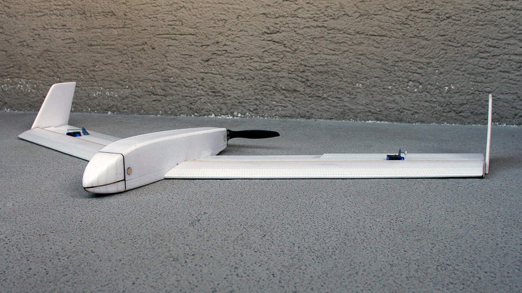
1) You will need a body that can support the tremendous weight of your antennas.  4 lbs is a "tremendous" amount of weight to throw around depending on what torque your servos can put out.  This is the one I chose to use.  It currently is holding two patch antennas each weighing about 12oz.  You can design your own, but you'd best have a CNC solution as any inaccuracies could make it not track correctly and there goes your aircraft.  All wood construction is fine for two antennas.

2) You need to decide which antennas you are going to use.  Frequency is HUGE on this.  Some antennas claim usability in a range of frequencies but that is NOT always legit.  915Mhz (aka 900Mhz) is very specific and your antenna could be "tuned" by the factory to "best" receive at 912Mhz and your screwed.  Read READ READ the description on the antenna your looking at.  I choose 1280Mhz (aka 1.2 or 1.3 Ghz) and 915Mhz patch antennas from L-COM.  If you use the 3DR radios from the DIY store (as I do) you might be thinking "what about frequency hopping"?  Your a nerd, but at least your an observant nerd.  Your radio MIGHT try to go outside the "effective" bandwidth (frequency spread your antenna can use well) but if it does it notes the signal drop (aka RSSI, Recieved Signal Strength Indicator) and will compensate for it.  Don't worry about this, just make sure your antenna is within the correct frequency range you will be using.

3) You will need two servos.  One for the tilting action and one for the pan action.  Tilt is the moving of the antennas only and the pan moves the whole AT, antennas and all.  Servos are actually complicated little devices.  I'll try to be precise as you can use the internet to find more details if you wish.  You want a servo that can do at least 110 oz-in of torque for two patch antennas, I'd recommend at least the karbonite materials to ensure it never strips out, but you can get by on the nylon standby versions.  Get a servo that does 90deg of rotation TOTAL.  Different manufacturers explain the total amount of rotation a servo can do in different ways, do your homework.  90deg rotation total is a standard servo.

For the pan I'd recommend at least 200+ oz-in of torque for two antennas and karbonite or better, as in all metal gears.  The reason for this beefiness is that when your panning range is at the limit of travel your AT will rapidly spin itself about 360deg in order to keep the antennas on target (1:50 second mark as an example).  The faster it does this the less time you are out of communication with your aircraft.  You can not avoid this behavior if you use APM Mission Planner as it is embedded in the software.  Building an AT that does not care about the pan range is very expensive to do as it starts to involve what are known as slip rings.  The military uses them and they are very nice, but very expensive due to the quality of slip ring involved.  For this pan action you want at least a servo that can do 360deg of rotation.  You really don't need more than that.

4) You will need something to take the information from your computer (again I used the APM Mission Planner to drive my AT) and turn those into a signal (numbers really) that your servo can use.  APM MP has two options currently, one for Maestro and one for ArduTracker.  The Maestro link is to a SERVO CONTROLLER card.  It can run up to 6 servos with the input provided by the micro USB cable but you will only use 2 of them plus the power pins.  The ArduTracker version uses one of the early versions of the APM called ArduPilot.  It is stripped down and cheap, you might have one from years ago, I don't know much about it, but this is a build that HappyKilmore wrote up on both of them.  I used it a lot and you can't go wrong reading it yourself either!  No matter which controller type you use to drive your servos you WILL need to download and install the firmware for them.  Maestro came preloaded and it looks like you need to find the firmware for the ArduPilot card from their website or this website's software library.  Programming your servo controller is vital, use this as a guide.  Basically you will find two numbers that bookend the total rotation your servo will do, then you will find the center of those bookends and then you will tell Maestro the "8-bit" range that it should use as commands to send the servo.  It's way critical to get these right, I lost hair doing it.

5) Battery.  Ok, servos run off of 5, 6 or sometimes 7V or more.  Most of them default to the RC standby voltage of 5V.  Mine are running off of 6V.  My battery puts out 12V.  If you do not find a way to step down the voltage from your battery to the CORRECT usable voltage for your servo you will fry your servo.  Your servo motor might smoke or the little tiny tiny circuit board in it might smoke, either way the reliability of it is gone and you should get a NEW SERVO.  If you don't and it fails in flight, you could lose connection!  A BEC (Battery Eliminating Circuit) is what you are looking for here.  I used this one.  If you do your homework, you can look up the idle and full load current consumption of your chosen servos and pick a BEC that will handle that load.  If you fail to get a BEC that can handle the spontaneous most highest ever load your servo could possibly generate then it will fry and your power to turn your AT will be gone, bye bye aircraft.

6) Battery Low Voltage Warning device.  You don't have to use this, but I would.  It's cheap and could save not only your battery but it will tell you when your AT is about to quit.  Its as loud as a smoke detector going off!  Buy a few of these and use them, don't be cheap like that.

7) Video Rx and Tx.  Rx and Tx is shorthand for Receiver and Transmitter.  I'm not here to tell you about these but to tell you that whichever system you use make sure it can fit to your AT.  Your AT is going to get crowded and messy.

8) Tripod.  You could come up with another thing to use, but that would be tantamount to reinventing the wheel.  The higher your AT is the further it can spread its signal.  Try to get one that does not have a lot of protrusions like mine has.  They will eventually entangle your wires.  Pay attention to which type of connector the tripod uses so you can design your AT to link to it.  Get one that is sturdy as a nice bit of wind could knock it over and your aircraft goes link dead.  Your AT should weigh around 7 lbs max, probably less depending on what you use. 

How Much Is a Picture Worth?

3689465172?profile=original3689465296?profile=original


3689465197?profile=original3689465339?profile=original

3689465422?profile=original

3689465362?profile=original

3689465468?profile=original

The Leg Bone is Connected to the Hip Bone...the Hip Bone is Connected to the...

Ok, here ya go:

*VELCRO AND ZIP-TIES you can use the crap out of them here!

1) Connect your servo controller board to your laptop, micro USB to USB for Maestro.

2) Servos connect to the servo controller board. For Maestro it will be servo 0 pin set for pan and servo 1 pin set for tilt.

3) Connect your battery to your BEC which is set at 5V or 6V or whatever your servos can handle (max it out).  Connect the BEC to the servo controller board.  For Maestro the pin set on the outermost is for the BATTERY power that will drive your servos (the USB cable powers the board).  DON'T REVERSE THE POLARITY, buy new stuff if you did.

4) Connect your battery (assuming Li-Po here) to the Low Voltage detection device, pay attention to it.

5) Connect your antennas to your 3DR radio (NEVER TURN ON RADIOS WITHOUT ANTENNA ATTACHED, buy new stuff if you did).  Connect antenna to the Video Rx.

6) You will need to splice off the power from the 12V side of the battery connection to feed 12V of power to your Video Rx, get some solder and a wet sponge, do a good job on the connection.  Connect the power to your Video Rx.

7) Connect your 3DR 900Mhz radio to the laptop (after you have antenna connected).

8) Use a bunch of zip-ties to secure and bundle all the wires.  This is important.  If you do a bad job here your AT will bind while its tracking and down goes aircraft.

9) VELCRO AND ZIP-TIES FOR THE WIN!

I have included pictures from all angles of my AT (version 2).  A few pointers here.  Build your AT as light as you can.  Get as beefy of servos as you can afford and fit.  You can make a wireless version of this AT if you have telemetry radios like the 3DR or the Xbee kits the DIY store sells.  I don't know how to do that but it is not going to be anymore complicated than what I have shown here, just more expensive.  Testing is done in two ways, first you setup your AT outside and point it north before you fire it up.  Then walk around the AT with your plane with everything linked up as if it was in flight.  Another way is to load a previously recorded flight from the APM2 logs and watch your AT go at it as if it was there.

Test this thing out as best as you can, it's now a critical point of failure for your entire system.  I don't recommend attaching your RC signal (typically your 2.4Ghz) radio.  Keep that one unmodified so you have a backup that you can rely on.

Read more…

3689465382?profile=original

Thanks to DIY Drones, I discovered there is another Aruducopter, now flying in South Carolina. None the less, my build continues and this time the RC Rcv deck was the focus.

The documentation on the AR6210 states that the remote receiver must be at least 2 inches away from the main and perpendicular to the main receiver. To accomplish this with the cable that came with my gear, I wanted to use a stack up plate with extensions.

After some sketching and judicious work with my mini mill, razor saw, and titebond wood glue...

3689465557?profile=original

3689465604?profile=original


The idea was to provide a rigid mount for the Spektrum modules while securing the wiring.

After cutting some saddle points, drilling holes for the cable ties and installing some sticky foam pads under the Spektrum modules, I then fabricated some stack up hardware out of the aluminum hex standoff hardware from my stash.

3689465585?profile=original

Here's a view from above demonstrating the passage of the PDB board cabling up through the stack.

3689465660?profile=original

Although not 'stock' (if there is such a thing), I wanted the APM2 at the top to allow me visibility of the LEDs, easy access to the reset button, easy connection of the USB, and easy access to the SD card. The APM2 inputs are on the other side from the Spektrum receiver to allow easier management of the wiring (longer run takes up the wiring). The 90 degree connectors also allow a lower profile for the top plate.

Next to order are the signal cables to connect the APM2 to the AR6210. Initial tests will be with the AR6210 powered through the APM2 connections. There is plenty of room between the two plates for my Vex 9.6V 1000mAh pack to power the AR6210 if so desired. The AR6210 handles 3.5 to 9.6 VDC.

Read more…

3689465140?profile=original

When started assembling my quadcopter I hated the thought of having to drill holes in the HobbyKing frame kits to get the APM2 mounted.  

So I took some measurements, made these adapters in Google SketchUp and submitting them to Shapeways:

3689465236?profile=original

Here are some more pictures, please forgive my lack of proper hardware, and bad camera, but you can see how they work.

3689465261?profile=original3689465274?profile=original If you think this is something you want you can have shapeways 3d print them here.  For the White-Strong-Flexible they are $2.16 each.  I'm sure having them made from plastic and not 3d printed would be way cheaper, but I have no access to manufacturing like that...

http://www.shapeways.com/model/604513/x550-to-apm2-adapter-v0-1.html

Read more…

Details:
radio: FlySky 9x flashed with Er9x
brain: APM2
esc: HobbyKing 30A
motors: EMP SERIES Outrunner Brushless Motor C2830 KV750
battery: Turnigy Nano-Tech 4Ah
frame: HobbyKing Q450

Surprises/issues.

I had to reverse pitch in my radio as default settings caused copter flying backward with stick pushing outside of me.

Motors connected as stated here. Is it normal?

This link is listed for 6-pos switch for Er9x but actually here is a simpler way. I would recommend linking to that instead.

Also, on this page you have listed flight modes but they are outdated and I can't find some of them on MP. Also there is no description of some modes that can be set in current MissionPlanner. Would be good to update it as I can't guess what those modes do.

Anyway, it was my first experience with copters (and other rc flying vehicles) and even with this strong wind it was a pleasure to fly a bit :)

More to come!

Read more…

Digital FPV with X8

3689464947?profile=original

Over the course of the last two weeks, I built a fully digital FPV setup.

Previously, I used an analog camera, Eagle Tree OSD, 1.3GHz Video Link and a handmade FPV ground station + FatShark goggles. But well... the video quality arriving on the ground was pretty bad when compared to current video standards, even when I used a GoPro as the video source.

This led to my current setup: Digital IP camera (really cool, it can be removed by screwing it out of the black holder) and a WLAN bridge. As the FatSharks do not support digital video they had to be replaced... by a 40" flatscreen hanging in my car (pics after this weekend). It's awesome!

Naturally, raw video is not enough: I need an OSD. First version used my laptop's crappy camera, read out using OpenCV:

3689464999?profile=originalThe data will be read out from a ArduPilot (should they ever be available again here in Europe... still waiting for mine) connected over the same WLAN. The serial connection will be emulated over the LAN using a WIZNet RS232 gateway. I already tried out the thing, works without a flaw! When the ArduPilot arrives I will also be able to use my antenna tracking code. Currently, without tracking, I get about 2km of range over something in the range of 100° in front of the receiver antenna, outside of that angle the framerate drops.

When the IP cam finally arrived there was a huge drawback: OpenCV cannot access it! The built-in Live555 server just quits with an error (something like "461 Unsupported Transport" if I recall it correctly). I tried many solutions, but the only solution that fully supported my IP cam (which is only streaming h.264 over RTSP) was embedding VLC using libVLC. This works really good and as a convenient side-effect my analog grabber is now supported without modification, too, as are all possible devices that VLC can access out of the box. This solution however has two serious problems: First, the video image is rendered onto my widget (I am programming in C++ with Qt) using direct render which means my pretty overlays shown above did not work so well. This one I managed to bypass (please ignore all the stuff lying around... plus big black thing for privacy reasons):

3689465083?profile=originalThe second problem is the following: VLC enforces a minimum network buffer latency of approximately 215ms. I can fly that thing, but it really is not pretty. So heres the question to the programmers: Is there a better way to grab h.264 encoded frames over RTSP? If your first thought is "Just drop VLC and use ffmpeg and live555 without the VLC overhead" I kindly invite you to implement exactly that after I sent you the source code.

Conclusion:

The video quality is awesome, flying around with the X8 really is fun. No interference with my 2.4GHz radio setup. The image lag is a problem, I would currently not try to land using the video strea, but once that is solved, this is the future!

Finally, two more pics of the hardware setup:

Camera with protection cover, WLAN access point.

3689465210?profile=originalRetractable landing gear!

3689465118?profile=originalIf anyone of you knows more about or has a solution to the streaming lag problem, every answer is greatly apprectiated!

Nicolas

Read more…

3689465060?profile=original

Found this on Gizmodo

It’s codenamed FishPi, and I’m already hungry. It’s going to consist of a Raspberry Pi computer, strapped to a solar panel and encased in a model boat that will navigate perilous seas all by itself.

Greg Holloway is the crazy sea dog who came up with the FishPi, and explains his ideas on the Raspberry Pi blog:

Massive 25-foot waves, 100km/h winds, torrential rain, lightning, and the Kraken. None of those things should be put anywhere near a Raspberry Pi. On the Atlantic Ocean all of those are common place, and that is exactly where I’m sending my Raspberry Pi.

FishPi will be powered by a 130watt solar panel, so there will be no masts or sails. The propulsion will run from batteries, charged by the solar panel, and it will utilise a Kort Nozzle to gain maximum thrust from what will be limited power.

On-board will be a compass, GPS and camera so we always know where the little adventurer is on its journey. It’s only a proof of concept right now, but Holloway is confidant it can become a reality. Oh please let it become a reality. I want to watch a model boat cross an ocean all by itself from the comfort of my office chair.

Read more…

2012 SUAS Competition Results

3689464378?profile=original

The results for the 2012 Small UAS Competition in Patuxent River, MD have been released.  The standings can be found here.

My team, Team Awesome from Embry-Riddle Aeronautical University placed 8th in flight and 13th overall.  It's our first year, and we used Ardupilot 2.0 in a Parkzone Radian.  

Read more…