We wanted to start narrowing down the reason's for why we keep losing the Shrike! We are starting with understanding which materials placed over the GPS module affect reception. We placed clear plastic, tape, a phone book, dow foam, aluminum foil, static brushless motor, powered and turning brushless motor, powered tx 2.4 GHz, and powered vtx 5.8 GHz directly over the module before booting the APM. We noted how many satellites connected after 2 minutes.
We found that most of the materials had negligible effects on satcount under the Flight Data>Status in the APM planner. Aluminum Foil, the brushless motor, and the 2.4 GHz signal created the largest interference.
Let us know how we could improve this experiment! We are not sure how well satcount correlates to the actual ability to navigate. Once we have telemetry we will be able to explore this further.
(I believe) I am a fast learning noob. It all started a year and a half ago when I was watching videos of monowheel vehicles and I saw this strange looking flying machines in one of the suggested. That was it. First time I saw a flying quad I fell in love and decided that this was the interest/job I had been looking for.
At the time I owned a wholesale/retail deli and wine shop in Greece and things didn't look out amazing. I worked 7 days a week and god knows how many hours a day doing deliveries to other shops and parties.
In the beginning I was watching videos of the draganflyer drones like crazy and saving money to buy one. Then I found out about the microdrones models and decided it was better, but when I found out about the cost of the later and the terrible customer service of the first, I started leaning towards the idea of making my own for a fraction of the cost.
That was how I found out about Mikrokopters. I spent months researching their (and other) site. By then I had closed my shop to avoid going into debt (this is sooo easy to happen if you're doing busines in Greece), and I had moved to the UK which I believe can give me more business as it had a much more developed film, real estate etc. industry.
So I started work as stage crew and in the meanwhile ordered an oktoxl. At first I felt useless in front of the amount of things I had to learn, but then I put it all in order, organised myself and managed to build it.
I was really pleased with myself because it worked like a clock first time! Then I decided I wanted an on/off switch for it and bought one from Maplin that fit snuggly between my centerplates. I thought everthing was fine, training my flying skills on manual flight, until I decided it was time to install the MK-Nav and MK-GPS.
As soon as I tuned GPS Hold on, the okto started spiraling out of control while rising fast. Being a noob, I didn't have the reflexes to switch te GPS off anf land safely. The okto started moving towards a road full of cars and my reaction was to crash land it to avoid causing an accident. It landed on the side, battery flew off and one of the riggers was heavily bent (strangely one of the shorter ones).
I thought that was it but I was amazed to find out only that 1 rigger, 1 bit of landing gear an a couple of propellers were broken!
When I tried to investigate what had happened, I entered the world of magnetic interference...
To cut a long story short, using a small compass, I went over all of my circuits as the were running (no props on!) and found out the compass was always pointing towards that stupid maplin power switch I had installed.
Removed that instantly but didn't stop at that. I decided that since I came this far I would try to eliminate as much interference as I possibly could, so I de-soldered all cables from my powerboard and re-soldered them so as to point away from the MK-tower where all the sensors are. I also installed bullet connectors to make future works and disassembly easier.
Next test flight I was extatic! My GPS hold in combination with altitude hold worked perfect and for the first time I could fly more relaxed.
A few days later I added my gimbal and camera (a canon eos d600) and got my first aerial videos. Had some trouble focusing and a lot of vibrations causing shaky video. So I added the camera triger so now I can focus during flight, but the vibrations are still a problem.
I eliminated some vibrations by adding elastic spacers to hold the camera gimbal but still, I'm having some issues.
I believe this is caused by two factors
a)because my frame after the crash landing is not 100% straight
b)because the propellers are not stiff enough
I have made a very short video with some of my better shots.
Further progress requires starting to desolder the Heroine 2200 boards. That was the 1st robot. The ages from 25-30 were spent purely devoted to that 1 thing, while everyone else was clubbing & getting married.
Heroine 2200 would still be a working robot, with new electronics. She was very unreliable with the old electronics, but modern vision systems & high bandwidth I/O could give her the accuracy to do the job.
There isn't a rationale for an automated method of organizing media. A human can get up & change it much faster than a machine.
So the equatorial mount naturally avoided gimbal lock without any crazy rules. The mane question is if it's fast enough. The takeoff move is so fast, it's not likely to keep up. The alt/az was far enough away to not need to be fast.
So the solution to the equatorial to spherical transformation was once again a quaternion rotation, just like the inertial navigation. You can invest a lot of effort into a discrete cosine transform, but the quaternion is intuitive. Then, the position calculation was the same as the alt/az mount rotated on its side.
After another round of bug tracking, the USB ports on the laptop's right side turned out to not support the webcam, while the USB port on the left side was the only one that worked. It was full blown lack of packets, even in isochronous mode. Yet another fine point to remember.
Webcam failure Vision could always be counted on to hit another failure point. So the problem is the ND filter makes everything look red. It could handle old 100W CFL's, but the new 100W CFL's pointed at the camera showed up as red & the 150W CFL's flooded it red. More tweeking or abandonment is required. A full range search with a known red marker might be required. Vision is an absolutely horrid, complete bodge.
So Marcy 2 would capture video, but only fly in a dark room or a room with only lights pointed away, which defeats the purpose of capturing video. It would be as practical as a vicon copter capturing IR video.
Board cam. The board cam with maximum shutter speed does a better job, but won't get the required smearing without its own ND filter, turning everything red.
There are more techniques, like requiring the blob to be a square or rectangle. Marcy 2 will require certain conditions, like not pointing lights at the camera & only flying indoors, away from windows or vicon cameras.
it was really solid. Its only problems of note were related to Marcy 1 being too unstable to stay in the sonar's limited range & no way of pointing the transmitter straight down.
Modern Marcy aircraft are so stable, they may work. Modern, centrifugal mounting may get it pointed straight down. It would be a lot cheaper than vision. A dedicated sonar system, with dedicated radios & micros might do it. The servos & fabrication make vision real expensive.
The PIC wasn't fast enough to do the required sampling rate, so it had a lot of aliasing & crosstalk. The op-amps didn't have a high enough frequency range. Doing the processing on a PC added a lot of latency.
Sonar using high quality, discrete preamps, a dedicated radio with no latency, all the processing done in microcontrollers & a fast ARM on the ground might outdo vision in cost & range. It would solve the problem of takeoff being out of vision range.
In the sonar department, the STM32F4 is so expensive, a completely analog solution with PIC for purely timing is more attractive. It was using a comb filter, integral, smoothing & short term maximum in software.
A reasonably priced analog circuit could only do a threshold & rely on the transducer's narrow band rejection. The blog posts showed a lot of aliasing & background noise. The PIC would have to set the threshold based on the false positives between pulses & time the threshold crossings, but it couldn't sample the waveform.
It might work, because the low sample rate & crosstalk were the mane problems. The comb filter made it more directional.
For another sonar recap, built up a send & receive test jig. The transducers do 24.5khz.
The sampling rate was a killer in the original. The original did 74khz. The oscilloscope does 130khz with 2 channels & 266 khz with 1 channel, still getting a lot of aliasing. The oscilloscope has a lot of quantization when using 2 channels & aliasing, even at 130khz.
There's no obvious problem with the LM324 preamp. The problem with sonar is the transducer doesn't start up instantly. The background noise is manely echos. A cheap ARM doing the full signal processing at a high sampling rate will be cheaper than an analog system.
Hackaday has the latest on the cool extreme lifting designs for the HobbyKing competition:
If you have a quadcopter and are looking for a beer delivery device, HobbyKing isputting on a beerlift competition The rules for the HobbyKing beer lift are pretty simple: lift the most beer with a quad/hex/octo copter and win a HobbyKing gift card.
There are 3 classes: Unlimited, which means a vehicle of any size goes, a 700 class for copters with a motor-to-motor diameter of 700 mm or less, and a Disaster class for the coolest crash.
The disaster category, a smaller quad built by [Gabriel Devault] was barely able to lift four cans of Coors Light water, while the current disaster class leader made a few valiant efforts to lift a keg. Protip: if you’re doing a blooper reel, Yakety Sax is definitely the way to go.
Today I had notification that there will be some new features coming in a firmware update for the DJI Wookong WKM, the latest V5.10 will be out in the next few weeks and sees some interesting additions, email from DJI:
Details of WKM new firmware 5.10
What’s changed?
Enhance wind-resistance when hovering.
Increase gimbal servo output response time and angle.
Gimbal pitch stability while X3 is for stick monitor or switch go-home.
What’s new?
PPM Receiver Supported.
Multi Gimbal Servo Output Frequency Supported.
Add Point Of Interest (POI) Function in IOC.
Add Intelligent Go-Home and Altitude Go-Home Functions in Fail-Safe mode.
Go home switch and user define go to home altitude.
It looks like the DJI team have addressed the slow gimbal reponse which was ok for stills photography but left the video users a little behind the pace, I hope that this will see the gibals now "snap" into action!
I'm not sure how they have improved the "wind-resistance" it was spot on every flight I have made, so we will have to wait and see what the WKM users think!
The biggest news here is the RTL at the flick of a switch with definded altitude, no more concerns about trees etc on the RTL, no more switching off that transmitter to "spoof" it to come home..... now who would do that :)
The new DJI OSD will be released in the near future which will allow the use of the Wookong M in First Person Flight mode!
This episode we focused on getting the APM's data logging feature working, as well as integrating the results with Google Earth and the Mission Planner. It works really well! We're looking forward to putting it on the Shrike and start recording our flights.
We are working in several airplanes adapting them to take ortophotography like professionals, we have already tested and working fine the first prototype based on EasyGlider by multiplex. This is a very good plane that forgives to bad pilots with a big problem it has few space but enough to carry a good battery and the necessary electronics.
For adapt of this plane we have to make the next modifications:
Airframe:
Opening in the airframe a hole just behind of the trailing edge of the wing, to accommodate the camera. Modify the camera trigger to can trigger the camera with a cable. (Fuji XP30). In the beginning we use the Canon IXUS 100IS but it give us some problems with the retractable lens because it clog with the dust in the landings.
Reinforcement of the airframe through a carbon rod in the up and down part of the airframe, to compensate for the weakness created by the hole of the camera.
Opening of a little hole to ballast the tail if it'll necessary set the GC, this hole is protected with a carbon tube for can insert and take out small bullets of lead easily.
Opening of a hole for the Mediatek GPS, just behind of the cabin. And open accommodation for the GPS cable on the border of the cabin. We have to do this because the integrated GPS on APM2 is covered by power wires and connectors.
Reduce the servo hole, cutting and pasting the arms of the semi-airframes.
Adjust the hole removing 2 mm side by side and make anchorage for APM2 with four nylon screws.
Shape two blocks of EPP that hold the battery on the right place, this prevent that the battery move to electronics in a crash breaking all components.
Cover the downside of the airframe with fiberglass tape, to reduce the stress of the elapor and increase the life time of the airframe.
Adaptation of the canopy, cut the wall inside of the canopy for allow close it when all electronics are inside it.
Cover the xbee with heat shrink tube, to protect it and prevent that the xbee won't come off of its base.
Put two net piece in the air inputs of the motor, with the purpose of the prevent that the grit can access to the motor and break it, when the plane landing.
Replace the original connector (Futaba or JR) for others with more pins that allow connect the two ailerons and the air speed sensor, we are use now this:
Wings:
Change the side of the aileron servos to up side, to prevent that the servos could be damaged with stones or shrubs, breaking the gears.
Reinforcement of the leading edge with fiberglass tape.
Structural reinforcement of the wing on its more fragile line just where finish the fiberglass tube. Through insertion of two platens of carbon fiber one near of the wing leading edge and other near of the wing tailing edge.
Instalación of airspeed sensor
Reinforcement of the horizontal stabilizer with a carbon rod.
Electronics:
Motor: Cobra 2814/20 850KV.
Batteries: 2S 5000 Turnigy Hardcase o 3S 2.200 Turnigy.
These are the modifications and adaptations that we have learned after crashing a few planes (Crast test), we look forward to the community of users to give us your comments. Our main doubts about this model are:
The way to cancelled the GPS on the daughter board of APM2, we are cut the path nºx of the GPS.
Tuning the PID, that black box that a few people know.
Synchronization of the clocks of the GPS and camera. For we can georeferencing photos.
So far we have prepared other models being the Easyglider the most evolved, Maja (Bormatec), Minimag (Multiplex) y Ursus (Marek), now we are working on Mentor (multiplex) for carry medium payloads (camera sony nex3).
Sorry, but the system didn't allow us upload more photos, and excuse me if my english is bad.
And thanks to all community and developers by make possible my project.
Tomorrow's a holiday in the US, so I'm going off topic for this bit of fun.
Via Mashable: "Produced by Fluxel Media with beats from musician Andrew “Nostalgia” Hill, the “Dubstep Dispute” video is beautifully constructed eye candy. Complementing the visuals is a remix of Muse’s “Knights of Cydonia.”"
I've been looking at my unused twist grip joystick for a while now thinking about hooking it up to a transmitter via the PPM trainer port.
I might go a step beyond this and get a new 2.4GHz Tx module and add that to the joystick to make it a transmitter.
Fly-Dream make an affordable and reliable 2.4GHz DIY module with three pins for GND,+,PPM in.
I've been able to generate PPM from an Arduino in the past so now it's a matter of hooking the pots in the joystick to the analog pins and the buttons to the digital pins. The pots move over a portion of the total travel in a joystick so my Vref will need to be a bit above the max voltage the pot will register. So if the pot only travels between 0 to half way and I feed the pot +5v then the max output voltage will be 2.5V.
I've also ordered an 8ch 12bit ADC I2C breakout which samples at about 12KHz. This will give me more leg room at reading resolution of 4095. The high resolution reading then goes through expo / trim / end point / sample filtering maths and comes out at a resolution of 1024 per channel. As far as I can tell the PPM output resolution does not need to be any higher than that, nor do I think the timing in an Arduino can get any better than that.
The hat switch can be coded to move the camera tilt servo. Might even pop out the digital hat switch and put a Wii joystick in there for tilt rate control.
With the 8 or more buttons on the joystick I should be able to code it to give me all the PWM levels needed for channel 6 modes on the Arducopter.
JVC and Sony are taking on GoPro with new small HD "action cams". The shape of these will possibly have much better aerodynamics than the GoPro... more in line with Contour's cameras. Notice JVC's is already "quad proof". I'm sure they had quad copter drones in mind. :)
JVC's appears to have more features, but I'm especially interested in Sony's as it's rumored to have image stabilization and a Zeiss lens. Not to mention, it looks really small and sleek. It would require a water proof case (if needed) like the GoPro, where the JVC is bullet proof, well "quad proof" out of the box. I haven't come across any details about whether either camera supports a live analog (SD) output. Post a comment if you know anything about these cameras.
Hi everyone! I'm very happy to announce our new u-blox based GPS board. The development teams and 3D Robotics have been working on this GPS unit for some time, and we have seen very good results on ArduPlane, ArduCopter and ArduRover. The Sparkfun AVC and the Quadcopter Rodeo were excellent opportunities to observe this GPS in action, and it helped Team Overhead win first place at AVC.
The device is pretty straight-forward. It has active circuitry for the ceramic patch antenna, rechargeable backup battery for warm starts, and I2C EEPROM for configuration storage. The units will ship pre-configured for ArduPilot Mega use, and the configuration file is available in the repository if needed.
This week, AUVSI (Association for Unmanned Vehicle Systems International), an industry group representing drone manufacturers, developers and operators, unveiled a "code of conduct" for operating UAS. While the code fairly broad and covers concepts of safety, professional conduct, and respect to laws, it also is not terribly specific. This might reflect the diversity of the people AVUSI represents (how specific can you get for 2,100 member organizations and 7,000 individual members?), but I believed it can be improved.
The area of drone ethics -- for journalism -- is even more underdeveloped. I founded DroneJournalism.org in December 2011 with the hopes of starting that conversation, with hopes that the website would become a "wiki of drone journalism and ethics." While we've made some progress in terms of building and operating drones, we haven't come too far in the way of establishing that code. So here's my first crack at a code of journalism ethics, "A Code of Ethics for Drone Journalists."
The full link to the post of the code is on the website, but the Cliffs version is: drone journalism is a branch of journalism, and so journalists who use drones for reporting have all the responsibilities that we traditionally expect journalists to have, but with some added responsibilities that come with operating spinning, flying machines that could hurt somebody.
Also, in my view, it's important not to just throw a list of requirements at a person and expect them to make sense of it. Many codes of conduct or ethics are just that: lists of bullet points that don't really provide direction or help with the application of the rules. I think a better approach borrows from "Maslow's Hierarchy of Needs," which hinges on the idea that to proceed to the next "highest" level of achievement, you first must solve some very basic problems.
So really, what I'm going after is like a check-list for drone journalism ethics. Here are the levels of this "hierarchy of drone journalism," starting from the bottom and working to the top of the pyramid:
1) NEWSWORTHINESS. The investigation must be of sufficient journalistic importance to risk using a potentially harmful aerial vehicle. Do not use a drone if the information can be gathered by other, safer means.
2) SAFETY. A drone operator must first be adequately trained in the operation of his or her equipment. The equipment itself must be in a condition suitable for safe and controlled flight. Additionally, the drone must not be flown in weather conditions that exceed the limits of the drone’s ability to operate safely, and it must be flown in a manner that ensures the safety of the public.
3) SANCTITY OF LAW AND PUBLIC SPACES. A drone operator must abide by the regulations that apply to the airspace where the drone is operated whenever possible. An exception to this is provided in instances where journalists are unfairly blocked from using drones to provide critical information in accordance with their duties as members of the fourth estate. The drone must be operated in a manner which is least disruptive to the general population in a public setting.
4) PRIVACY. The drone must be operated in a fashion that does not needlessly compromise the privacy of non-public figures. If at all possible, record only images of activities in public spaces, and censor or redact images of private individuals in private spaces that occur beyond the scope of the investigation.
5) TRADITIONAL ETHICS. As outlined by professional codes of conduct for journalists.
These are pretty basic guidelines for the time being (not intended to be all-encompassing), but we hope to fill out the gaps with the help of the droning community. Any opinions or comments are welcome.
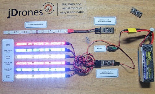
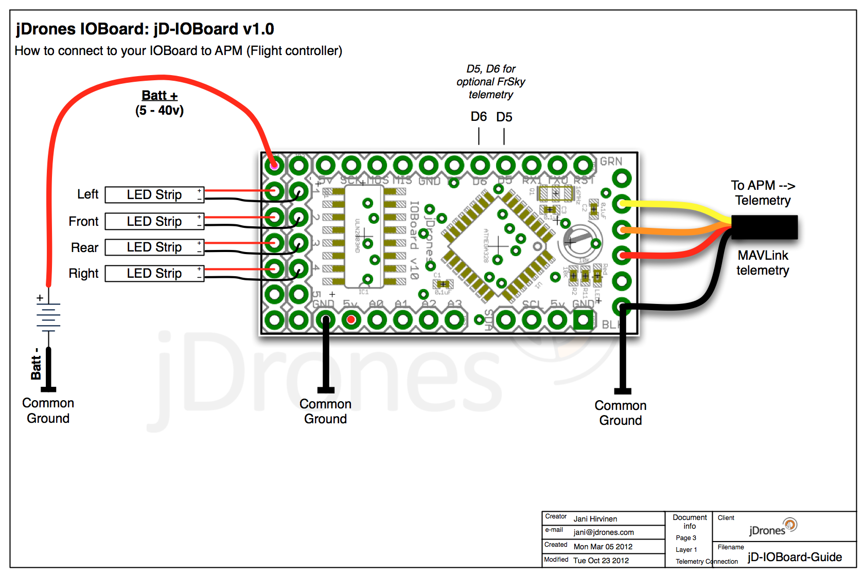
You had some problems on driving LED strips or something else?? Well no problems anymore.... We have seen people making all type of darlington/transistor and similar hacks to drive their LEDs, Sirens and so on but they all need a lot of hacking and they might not be suitable for long term solution.
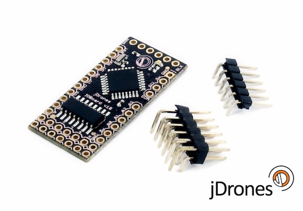
We answered on this call and made fully Arduino compatible called jD-IOBoard that can run Single LEDs, LED Strips, Loudspeakers, Buzzers, Power switches and so on. It's upto your own imagination on what all you can control with this board.
So what does this board actually do?? It has fully Arduino compatible ATMEGA 328 MCU and Darlington array to driver high power outputs. Also I2C pins are exposed and same as many TTL level IO and Analog pins. As you can see from picture above.
Board has:
- 6 x High power outputs, max. 500mAh / 50 Volts
- 4 x Analog inputs (6 if you don't use I2C port)
- I2C port for controlling, listening I2C messages
- 6 x TTL level GPIO pins (8 if you don't use FTDI)
- 1 x FTDI port
3 high power outputs can also be controlled by PWM output while another 3 are just normal "On/Off" outputs
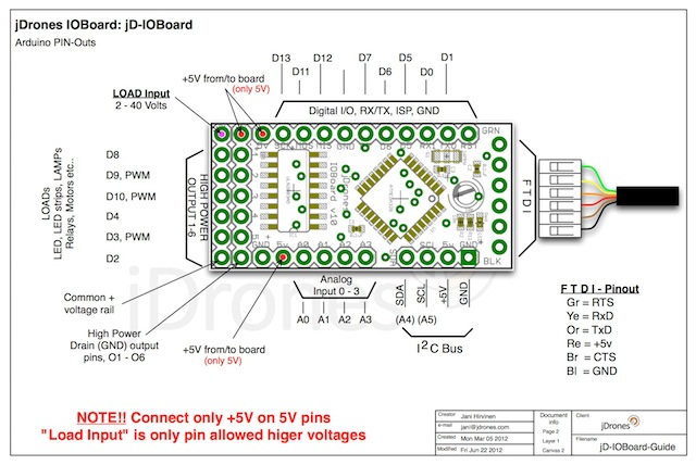
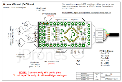
How those Arduino pinouts looks like:
Connecting LED's,Buzzers etc is really simple. Just use one of output pins on end of the board. Below you can see examples on how to connect LEDs or LED Strips on it.
Pictures does not give enough credit for how it works so we made small video to show just few examples on how to use it. There are many other ways to do it but this should give at least some idea what/how to run it. So have fun watching it.
Get yours from jDrones Store: jD-IOBoard and have a blink blink.
Ps. There are some nice features coming to this board shortly...
Today Hobbyking added a stabilisation control board for fixed wing aircraft to their catalogue. This board supports conventional, flying wings (delta) and v-tail aircraft, easily selectable by on-board jumper. Unfortunately for v-tail aircraft an y-cable is needed if you are using 2 servo's.
The board is controlled by an Atmel Mega168PA 8-Bit RISC based micro controller and utilizing a single high precision 3-axis MEMS gyro and independent gyro gain adjustment for tuning aileron, elevator and rudder.
Not includeded are servo leads to connect your receiver to the i86AP Flight Stabilisation control board. You will need 3 of them, don't forget to include in your order.
I had a quick glance at the manual (which can be downloaded here) and it seems that it provides good information how to use this board.
Specifications: Input Voltage: 4v to 6v DC PWM Output: 50Hz, 1020-2020us Gyro scale: +/- 1000dps Gyro sample rate: 1KHz Operating temp: -40° C to 85° C Size: 30mm x 40mm Weight: 8g
Another successful flight to over 100,000 feet with the same APM2 and 3DR radios on board. This picture is the balloon exploding at over 100,000 feet. Total flight was 101 mins this time. The APRS tracker failed this flight but the package was recovered in a 1/2 hr by a citizen calling the phone number on the package !
In about 2 weeks we are preparing to launch the balloon glider combo and fly the glider back by a joystick on APM2 via mavlink.