From @DroneMapper: "Near Infrared UAV Imagery Example - Vineyard in Chile (268 12MP 2D images processed via DroneMapper)
All Posts (14049)
Sort by
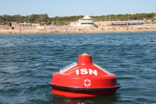
We have been working system that consists of buoys installed on the ocean to send real time data about beaches to
apps that we have made for iOS and Android. This system was deployed by Vodafone Portugal Foundation last summer as a pilot project and this year we have improved it further.
We are actually using our UAV electronics with an IMU on the buoys. In the end we chose to use the GPS for measuring wave height but we also have worked on it through the accelerometers as backup.
We use the GPRs network to feed the data from the buoys but have an RF channel open with the buoy to
monitor it locally and change configurations just as we do on the UAV. We are actually using the same system
on ground measurement stations.
The data from the buoy is fed to servers in the cloud that then provide it to the end users mobile Apps.
Besides being useful for surfers and beach goers one of the important measurements is the UV Index. We hope it helps educate people on when not to go to the beach.
There's a short explanation of last years pilot project with photos here
http://praiaemdirecto.com/info
A summary video
https://www.youtube.com/watch?v=8Af77IFRngU
You can watch a short video from the company that installed the buoys for us:
https://www.youtube.com/watch?v=ykxNl6JeNi0
You can try out the apps here.
iOS
http://itunes.apple.com/us/app/praia-em-directo-fundacao/id455026316?mt=8
Android

Hi,
I found this Arduimu+ V3 on Ebay. Green instead of purple, with same price.
http://www.ebay.com/itm/ArduIMU-V3-Module-/270994525798
Original or clone ?
Angelo
hey,
in june this year we went to norway. i packed a lot of stuff with me and of course i had to take with me the flying machine (or to be precise, flying machineS):
we went there for 2 weeks, drove 6100km in total and it was actually great (and damn expensive) fun. friends from http://helicam.ee borrowed me their prototype, foldable y6 which was a big help (hiking in mountains with cs8.. better not). so we did some photos, here
and there (that's preikestolen below and you can read a bit more how we did this photo here)
however, most important part of the trip was not photos, but rather video :) and here you can see very short showreel from our flying adventures, hope you will like it. and turn on sound, or otherwise you'll lose half of experience :)
hope you'll like it :)
From BoingBoing blog, without much background
Yes, we have a general prohibition on posts that discuss military uses of drones, but this was too funny.
(via @Drones)
here is an interesting article about drones and future uses -
http://www.thepunch.com.au/articles/this-is-your-pilot-speaking-im-not-on-board-right-now/
richie
Hi Guys It has been a while .My plane is probably 1/2 built I has been "modified and is now a EDF. I covered one of the wings with ultra cote I have to re iron it a couple of more times to get it smooth You think you got it leave it for a while come back and you find spots you missed I started covering the ailerons and flaps also. Then I have to put on the hinges and rigging to the servos in the center of the wing . I found out just recently the word Lypo and Lead start with the same letter and are not much off as far as weight goes ! In the picture of the batteries on your left is the 6s 22.2v 5000mah 30 c lipo that weighs as much as the plane beside it the little green thing is the lipo out of my radian pro to give it some scale and on your right is the 100amp phoenix ice ESC by castle They are going to be suspended in front of the EDF for cooling. The fuselage still weighs under a pound I added air scoops on each side and drilled many more holes to take the added weight back off . The EDF is mounted on "U" shaped nylon rails I have to make a thrust tube behind the EDF and re cut the foam I already made for the fuselage I am going to cover the Exoskeleton and fuselage foam with Rip stop nylon Sail repair tape. I have to build a elevator and I am going to laminate a over sized partially balanced rudder . I might make it a tail dagger
with "Tundra tires" ( I still have the landing gear out of the "Somthin Extra and a 26 cc gas engine if this doesn't work) also is a picture of one of the full size metal gear servos for the rudder and elevator at the back of the plane. You guys have a good day!
If someone has problems with the video (music copyright) please check this link: Video
Hi all,
some weeks ago while I was watching a Formula1 race I started to think in this idea, why not develop a Formula1 shape quadcopter? I was thinking about the best way to fit the shape of an F1 car with a quadcopter and then I started to work on this. With red coroplast plastic and a scissors I made the shape of the car (profile shape) and then I print some stickers from images of the car and this was the result:
The truth is that I have been playing with quadcopters and multicopters for some years and I always dislike the simetric shape of this machines (I tried to modify this a bit on old projects). In my opinion they are a bit ugly, so one thing that I really like about this project is that it don´t seem a quadcopter. People first see a race car and then when they see the props they ask me, but this really flight?
The setup of the quadcopter is the same of this project: Indoor fun with tiny ArduCopter but I have changed the electronics by an APM2.0 and I am using 5x3 props (normal and counter-rotating) from HobbyKing on a 2S800 battery. I have adjusted a bit the PIDs for the weight and the shape of this project and I have configured the yaw a bit more agressive in order to "drive" the quadcopter more like a car in the corners.
The result is a funny project and I think that Ferrari should look at this updates for their cars... ;-)
This post in Spanish: Formula1 Quadcopter
Jose Julio
Nothing is ever perfect. Or even as right as we might like. But I've been holding out on you, my friends, focused as I was until lately on moderating, I haven't been taking the final steps to share my code, photos and images of my aircraft, and other files I've been working on, such as this X-Plane model of an ArduPlane based on the Bixler.
Well, I hung up that moderator hat to focus on contributing in other ways. I wish I could say that gave me the free time to polish this model to the point that it is where I'd like it to be for a general release, but the truth is that I simply added more projects to my plate. I'm not going to let it slide anymore, so this is getting released as it is, and as condemnation and criticism shames me sufficiently, I'll fix it up and release more often.
The model originally came with a 1.5MB, 20 page "developers" guide that spelled out in painful detail the scaling and specific characteristics of the plane. I haven't updated it, it is even more boring than this post, and it isn't required to get flying, so please allow me to bring your attention to the most important aspects of using this model first. Then I'll add some details for those of you who are interested afterwards (and if you really like to slog through overlong explanations, ask me and I'll send you the documentation, in all its outdated gorry...err ... glory.)
Installing
Simply unzip the model files in your "X-Plane/Aircraft" directory. Make sure you are using X-Plane 9.70 or higher.
Before You Fly
Assuming you plan to fly Hardware-in-the-Loop, follow the instructions in the manual, but use the following adjustments.
- Increase the number of flight models per frame. In X-plane, find the menu item for "Operations & Warnings", and increase the flight model per frame to at least 3.
- In APM Planner, Simulation, change the throttle gain to "5000."
- In APM Planner, load the attached Parameter file, then recalibrate your radio and setup your modes according to your preferences.
That is all you really need, but here are some more details for those of you who are interested.
Runways, Grass, and Landing Gear
As you can tell from the video, in keeping with the physical model, there is no landing gear on the plane. A Bixler is typically hand launched, but X-Plane does not include a virtual hand to throw the plane. In reality, there are hidden, invisible skids on this model, to allow the plane to "sit" on the ground properly. Just give the plane full throttle and get it off the ground before it heads for the rough grass, and it should lift off fine. If you get off course, go off the runway, or get turned too severely, it will get "stuck" (as it would in real life.) I've reduced the friction of the "skids" just enough that it will take off from the belly, which is more than it will usually do in real life, but I did not think you'd mind if, on this point, I departed from reality. Most of the time I perform full automatic missions, from take off to landing. If the wind is too strong, or if the mission script is not right, the plane will sometimes go astray and get stuck in the grass. As with after a landing, you simply re-open the plane (or re-open the airport) and you are set for another run.
A Brief Note on Scale
The X-Plane simulator does a fantastic job approximating flight in fantastic detail, and this model was prepared to leverage quite a few features, including drag of the onboard gear, Reynolds numbers, realistic weight, center of gravity, motor and propeller performance, and at one time (now disabled) I even added battery life into the model. However, with models under 5 lbs / 2.2 Kg, the simulator tends to crash. Well, sometimes the plane crashes and sometimes the entire simulator crashes. There are two things done here to address this issue, and it has been very reliable for myself and for everyone who has so far reported back to me. The first is to increase the flight modes per frame (see above) and the second is to scale the airplane such that it is at least 5 lbs. I have adjusted every aspect of the plane to balance a realistic simulation with this scaling requirement. Thus the plane is scaled at 1.7x (size) and about 3x in terms of weight to maintain the correct relationship between wing area and weight in scaling. Proportional changes to Reynolds, motor power, propeller dimensions were all adjusted in concert in an attempt to be as authentic as possible. If you want the specific numbers you can mine the model or ask me and I'll send you more details.
Trimmed, Level Flight
I hope the pilots here will forgive me, this is a note for folks with less hands on experience. Planes are designed and trimmed for specific flight speeds. Many planes flown with more throttle will tend to pitch up and climb, and if the forward airspeed is below the designed speed, they will tend to pitch down slightly and lose altitude. Pilots correct this by trimming the plane, and the APM could do this with the P_to_T parameter (which I have not explored, and which I have also not set in my real life Bixler parameter files... nor have I seen any real life parameter files yet that have this set.)
So it is helpful to know that I designed this plane to fly level at about .480 throttle. If you find it pitches up or down and does not fly exactly level in the simulator, take a peek at your throttle setting. I normally display the throttle data on the screen during flight, and you can do this easily as well. Look at items #25 and #26 in your X-Plane Data Input & Output. The circled items below are essential for HiL, but the items I did not circle are recommended for onscreen feedback.
A Big Thank You
I want to say thank you to a few people who either directly contributed or cannot be left out of any list of thanks related to ArduPlane (and, sadly, I will leave people out, my apologies.) A big thank you to:
Chris Anderson, Doug Weibel, Jose Julio, Jordi Munoz, Jason Short, Andrew Tridgell, Michael Oborne, Paul Mather, Bill Premerlani, and everyone else who shaped ArduPlane and, without whom, this work would neither be possible nor of any value. And a special thanks to Knut Lagies, Didier, Robert Elgin, Yury, David Buzz, Thomas Berndt, Justin Beech, Colin Bouriquet, Michael Brown, George Dimitoglou, Kevin Finisterre, David Jones, Mike, Carlos Moreira, Linux Penzlien, Pavel Skotak, Eric aka Eagle, Dusan Trenic, and Stephen Wong for flying a previous version of this model and providing feedback.
A Note on Reproducibility and PID Tuning
These PIDs work well for me. However, since each HiL computing environment is different, variations in the resources of the OS, running processes, and especially background tasks such as an Antivirus scan can dramatically affect the latency of control and sensor data to/from the APM. If these PIDs do not work for you, check that you don't have resource hogs tying up your memory or CPU, and please do share your PIDs as you get them dialed in better for your environment.
Here is a previous video (very cheezy; I was having fun with an iMovie template) announcing the plane, provided for your amusement.
What about X-Plane 10? Flexible Wings?
Yes, I have produced a variety of different models, including an X-Plane 10 model leveraging the nifty bendy wing features (and in real life, the Bixler's wings flex like crazy.) However, as X-Plane 10 was brand-spanking new at the time, there were issues in using it for HiL that, combined with the additional cost and lack of backward compatibility, caused me to give up this sexy feature and restrict myself to an X-Plane 9 model. You can open and fly this in X-Plane 10, and you can also open and upgrade it to a native X-Plane 10 model using Plane-Maker yourself. If there is enough demand, I'll explore flexible wings and X-Plane 10 again. I have also made 3 channel planes and other variations. If you are really that excited about a variation, please let me know.
And Now, the Files (attached)
I have the TH 9X channel transmitter, and the biggest problem I have with this remote is the most accurate way to change flight modes is by flicking one switch so whenever I want to change a flight mode I have to change flight mode 6 because flight mode 1 is always stabilize and simple mode, now this gets a bit irritating so one day someone posted a blog here of a potentiometer with 6 clicks and some variable resistors to each click on the potentiometer so you can define the PWM. I bought this for about $15 here and it was at my door in about 4 days, it was crazy. I bought the unsoldered version so I had to do some fine soldering.
Now the variable resistors has 3 legs (+) (Feedback) (-) it does not matter which way is the plus and minus. I took an old parallel cable from an old hard drive mounting and cut 6 strips from it about 10cm long and cleaned the plastic from it and soldered the two most outer wires from the bunch to the (+) and (-) and then Is soldered to all of the pins a piece of wire.
Once all that was done, I soldered the 4 inner wires to a number on the potentiometer, and the previous potentiometers brown wire where it said brown and the black to the black and red to the red. I then soldered the 2 most outer wires to the black and the red.
I then broke of the previous potentiometers plastic housing and drilled a bigger hole in the cover so that the new potentiometer can fit. Please note the extra smaller hole on the left hand side of the big one that I made, it is so that the new potentiometer fits snug into the hole.
I then fitted the nozzle thru the whole tightened it with a nut on the outside.
I then found a nice place to hot glue the variable resistors to the back of the cover so it is easy to come by with a screw driver because you have to adjust the variable resistors so that the signal is set to the correct PWM for the specific flight mode.
And then I started tuning the inner flight modes because the most outer two knob settings is always flight mode 1 and six and knob area 4 is also always flight mode 1. First set your aux-ch option to the following. Please note channel 5 is set to Pit trim.
I opened flight planner and started turning the variable resistors on each unit until the green on the dropdowns showed on the correct place.
An now I have 5 accurate flight modes to choose from without any hassle.
Hope it was help full and happy flying.
First flight went well. Was able to test Manual (Works! :D), Stabilize and RTL modes.
The plane is a semi-stock Parkzone T-28 Trojan. The servos are all stock. ESC and Motor are upgraded to E-Flite 80AMP ESC and Power15 Motor. Generic 5v BEC powers APM and Radio equipment and nav lights. RC Radio gear is JR 2.4Ghz. Telemetry provided by 3d Robotics Telemetry Radio.
This was using older firmware (Stock as of when the board was hand made by the awesome folks at 3dRobotics, not updated to new MAV1.0 FW). I have recently updated to current firmware (Using Mav1.0), and I am in the process of testing all settings and preparing for my second flight. I would like to add a Amp/volt meter, and AirSpeed sensor before my next flight, as more data = good thing..
With more than 200 parameters to "tweak", the ardupilot-mega system can be a bit intimidating. Documentation is critical, but in a fast-moving project like APM, it is almost impossible for the documentation to keep up with the code. A major improvement in the code was the addition of inline documentation for the configuration parameters, several months ago. This documentation has been visible recently in the superb new configuration screen in Mission Planner, which provides a detailed description, units, defaults etc. for many key parameters.
Now, this documentation can also be found in the Wiki. Best of all, this wiki page is dynamically generated with every single new revision of the code, just like in Mission Planner. As new parameters are added, or existing ones modified, the developers can change a few lines of comments and the wiki page will update to reflect that change, instantly, from code to wiki.
Visit the new dynamic wiki page Parameters and their meaning
Scientific American reports on plans for "volocopter", a human-carrying multicopter from Germany:
Inventor and physicist Thomas Senkel created an Internet sensation with the October 2011 video of his maiden—and only—test flight of a spidery proof-of-concept 16-rotor helicopter dubbed Multicopter 1. Now the maker of the experimental personal aviation craft, the European start-up e-volo, is back with a revised "volocopter" designthat adds two more rotors, a serial hybrid drive and long-term plans for going to 100 percent battery power.
The new design calls for 1.8-meter, 0.5-kilogram carbon-fiber blades, each paired with a motor. They are arrayed around a hub in two concentric circles over a boxy one- or two-person cockpit.
After awarding the volocopter concept a Lindbergh Prize for Innovation in April, Yolanka Wulff, executive director of The Charles A. and Anne Morrow Lindbergh Foundation, admitted the idea of the multi-blade chopper at first seems "nutty." Looking beyond the novel appearance, however, she says, e-volo's concept excels in safety, energy efficiency and simplicity, which were the bases of the prize.
All three attributes arrive thanks largely to evolo’s removal of classic helicopter elements. First, the energy-robbing high-mass main rotor, transmission, tail boom and tail rotor are gone. The enormous blades over a normal chopper's cabin create lift, but their mass creates a high degree of stress and wear on the craft. And the small tail rotor, perched vertically out on a boom behind the cabin, keeps the helicopter's body from spinning in the opposite direction as the main blades, but it also eats up about 30 percent of a helicopter's power.
The volocopter's multiple rotor blades individually would not create the torque that a single large rotor produces, and they offer redundancy for safety. Hypothetically, the volocopter could fly with a few as 12 functioning rotors, as long as those rotors were not all clustered together on one side, says Senkel, the aircraft's co-inventor and e-volo's lead construction engineer.
Without the iconic two-prop configuration, the craft would be lighter, making it more fuel efficient and reducing the physical complexity of delivering power to the top and rear blades from a single engine. Nor would the volocopter need an energy-hungry transmission. In fact, "there will be no mechanical connection between the gas engine and the blades," Senkel says. That means fewer points of energy loss and more redundancy for safety.
E-volo's design eliminates the dependence on a single source of power to the blades. As a serial-hybrid vehicle, the volocopter would have a gas-fueled engine, in this case an engine capable of generating 50- to 75 kilowatts, typical of ultralight aircraft. Rather than mechanically drive the rotors, the engine would generate power for electric motors as well as charge onboard lithium batteries. Should it fail, the batteries are expected to provide enough backup power so the craft could make a controlled landing.
More details and render videos at the E-Volo site.
The Re-Mote is a new product by FAST Robotics. With the Re-Mote, you can trade out your expensive R/C Transmitter and use your own USB Controllers to control your Robot. The Re-Mote is fully MAVLink compatible, XBee compatible and is powered by 2 AA Batteries for up to 2 hours of use.
The way the Re-Mote works is that you hook up your USB Controller (or 2) to the Re-Mote, use the Configuration GUI to tell the Re-Mote how to interpret commands, such as button pushes and axis movements to relate to MAVLink commands to your UAV. For each USB Controller(s) and Robot, the GUI makes what we call a User Profile. After you finish making this Profile Bucket File you can download directly to the Re-Mote, download to a Micro-SD Card on the Re-Mote or save this File for later.
When you are ready to use your Robot, no need to bring your computer! Connect your USB Controller to the Re-Mote (which powers your USB Controllers), install your own XBee compatible Radio, select which User Profile to use and you are ready to go!
Current Status: As of 7-July-2012, we have performed the following work:
-Neat Feature Animation Video!
-Physical housing mostly complete.
-Critical code has been developed, which includes developing/testing for USB Controllers and sending data via MAVLink to QGroundControl.
-Configuration GUI has been started.
Work to be completed:
-Re-Mote Schematic and PCB Design
-Bill Of Materials
We are working very hard on this and hope to put on Kickstarter within 1 month. For now, we are anticipating an assembled Re-Mote (RF Radio not included) to cost about $65 on Kickstarter and $75 retail. These numbers are a work in progress so they may go up or down.
All of our code, designs, schematics and everything is open-source. As the Re-Mote is still a work in progress some of the information here is a little sparse, but here are some links:
Re-Mote Git Hub Repository
Re-Mote Wiki

Recently Ars Technica did a piece on software defined radio, using the Phi product as a centre piece, it got me thinking about its applications for drones.
Software defined radio basically allows people to write programs which interact with radio waves on a host of different frequencies (100 kHz to 4 Ghz), what this means is instead of having a chip dedicated to GPS you could have this card in your computer and instead run a GPS program. While this may not sound like much, something that has always bothered me about my drones is my use of a third party datalink that I have limited control over, and I believe this kind of thinking is the answer. I would certainly love the ability to apply my own compression methods to my data packets and video and choose my own method to send them (i.e. on which frequencies).
I also like the ability to have different protocols opened up by simply developing the software to them rather than developing or reverse engineering the hardware. Good examples of this might be giving people the option of receiving aviation communications through UHF/VHF and interfacing to GLONASS.
Currently I see the major disadvantage to this technology is its PCIe requirement (Raspberry Pi does not support this, so a traditional motherboard with a traditionally large surface area would have to be used), and no doubt the processing power required might not be trivial.
Do you think this has potential for drones?
The current issue of online/iPad magazine The New Inquiry is all about drones. It's a bit arty/academic/political, but pretty interesting all the same. The content is subscriber-only, but it's just $2/mo to get and you'll have instant access. Yes, DIY Drones is mentioned.
Some of the articles are a bit of a reach ;-)
But others are very solid. Here's the complete table of contents:
RC Arduino is a cool site that documents how to add an Arduino with gyro sensor to a RC car to make it more more controllable, basically "driving by wire", rather than directly, with the Arduino making sure it doesn't spin out.
They explain:
"All of the throttle and steering commands in the car in the video are coming from an onboard Arduino. The Arduino is reading the incoming signals from an (drivers) RC Receiver and also a gyroscope within the car. It is using this information to assist the driver by controlling the yaw of the car under acceleration, braking and cornering."
There are some other cool Arduino-based RC car project there, too, so check it out.
I am sure we have all been there; there must be a servo connector loose somewhere, you firmly press each one with fingers too large to press just one connector, you wondering whether the wires in each connector are well-crimped, you stare in dismay at at the spaghetti emerging from the APM. While working on my computer last week I just may have come up with a solution. Why not use flat ribbon IDE cable instead and 3x8 headers (http://www.pololu.com/catalog/product/1038) instead of 3 conductor servo wire? Here is what I did:
1) Reduce the width of the IDE cable to 24 connectors (3 conductors x 8 channels)
2) Split the ends into groups of 3 conductors
3) Strip the plastic off
4) Split each group of 3 into individual wires
5) Tin each wire
6) Tin the 3x8 plug
7) If you want to use very thin heat shrink tubing, slide it over the wires now
8) Solder with a quick touch
9) Cover in liquid plastic / slide the heat shrink in place and heat it
10) Repeat for the other side of the wire
That's it! Now you have connector that is much less prone to move about or come loose, there is less risk of bent pins, you can be press it in or pull it off easily without pulling on the wires, and it has the benefit of soldered connections. It may not be lighter that a traditional setup, but the flat ribbon can fit above or under batteries without any issues, takes up less space and just looks much neater than the traditional spaghetti.
If I am not mistaken, you can also reduce weight a little more by only conn
ecting 8 wires to the signal pins and connecting a single power and ground wire. If you still want to make sure each channel still has signal, power and ground, just solder a small wire across the power and ground pin rows on the back of the 3x8 connector. Would love to know if my theory holds water!
Notes:
!) The 3x8 plugs fit my ImmersionRC receivers perfectly, but not my Hitecs receivers. I am not sure it is possible to get them in different widths, by you can always use the 3x8 plugs on one and and traditional servo connectors on the other, at least this cleans up the spaghetti!
!) Make sure the wires line up correctly
Happy soldering!
Robert
Here's a little vid of my DIY WKM Heavylifter Hexa
Please Enjoy!
Jacques