All Posts (14049)

Sort by
Developer

Free Webinar: Developing code for the APM

3689466742?profile=original

On Monday July 16th 2012, at 5pm Pacific Time,I will be hosting a 90min webinar on Developing for the APM. 

Guests will include several members of the development team and from 3DR.

The webinar will cover some of the following topics, time permitting (we may have to split it into two webinars):

Part A

  • Setting up a development environment on Windows, Linux or Mac
  • Getting the code (download and git)
  • Compiling the code for different configurations

Part B

  • A guided tour of the code, explaining how different pieces fit together
  • From idea to running code - code, compile, test, document, create a patch and submit for review (for a bug or feature)
  • Developer support tools: autotest, autobuild, SITL, HIL, jenkins

If you would like to attend this webinar, please respond here:

(this is a courtesy RSVP so we can evaluate attendance - the meeting is open to all anyway)

http://bit.ly/MIcKHe

If you cannot attend on this day or at this time, use the link above to tell us a better time/day for the next webinar!

TO JOIN THE WEBINAR (on the day of the webinar)

Go to: 

    https://join.me/619-558-336  

For audio, join by Internet or using one of the international phone numbers:

Internet: Click the telephone icon on the webinar screen (URL above)

Telephone: Click on the telephone icon to see a list of numbers. Or see the FAQ: http://bit.ly/NKRY4j

There are phone numbers in about 30 countries. 

Prerequisites

To get the most value out of the webinar it is suggested that you read the wiki (especially the Appendix) and have the latest Arduino IDE (1.01) and a copy of the source code. You also must have at least a basic understanding of programming languages, but you do not need to be a programmer (this is for all levels of experience)

Comments and feedback appreciated. 

Read more…

Throwing more feeds & speeds at a problem

sonar98.jpg


So sonar was officially back again for another swing at a home run, with a lot more clockcycles.


bear.jpg


AP

It was a hot one.

Unlike the last attempt, beacon triggering over USB was neither an option nor accurate enough.

sonar89.jpg

sonar88.png


So that was propagation delay over 10ft using a hard wired trigger & 266khz sampling on a PIC.  It was extremely accurate but not reality.


Past attempts to synchronize beacons with radio packets were very ineffective.  That requires a mode of communication with a constant latency.  USB was good enough for 1 meter accuracy.

The 802.11 system currently in use is even less realtime than the USB system in the old days.    The aircraft would use IR for a trigger.

sonar91.jpg


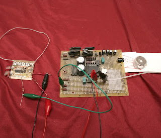
It came from a chinese toy.

sonar92.jpg


The IR emitter was toggled at 38khz & ran on 1.5V.

sonar90.png


The intended IR trigger naturally failed.  38khz modulation was too erratic.


That leaves only a draconian complex system involving a dedicated, hard modulated 900Mhz radio set. The radio set would be used to send triggers using a hard realtime bit banging protocol.  An 802.11 radio would be omitted from the ground station.

sonar93.jpg

sonar94.jpg

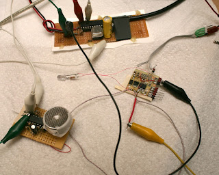
The MRF49XA radio in raw mode allows a trigger to be sent with 256khz precision.  Getting raw mode requires clearing the TXDEN & FIFOEN bits in the GENCREG register.  Then, the FTYPE bit in BBFCREG needs to be set for analog filtering.

Getting the maximum bandwidth requires driving the FSK/DATA/FSEL pin on the transmitter to 0 or 3.3V & reading the RCLKOUT/FCAP/FINT pin on the receiver.  You're looking at a lot of pins for a full duplex radio set.

The FSK pin outputs a lowpass filtered voltage which maxes out at 115 khz.  The FCAP pin outputs the unfiltered voltage at 256 khz, so for a sonar trigger, you need the 256 khz voltage.  The voltage is not linear, but either 0 or 3.3V.  You would need a codec to get audio through it.

It's important to get the GENCREG register address right, which happens to be 0x80, exactly the same as the TXDEN bit you need to disable. 

sonar93.png

Not as blazingly accurate as the hard wired trigger. 

a2422254-109-sonar34.png


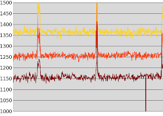
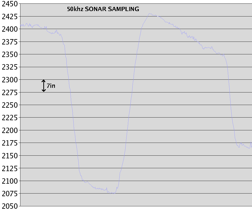
An original graph from 2009.  The 2 graphs covered the same distance.  No dramatic improvement is jumping out from the extra firepower, but the original USB clock synchronization can be considered very high quality.

Even with the waveform massively oversampled at 266khz, things weren't decisively different than the experience with 74khz.  The massive signal processing developed in 2009 was still required.

The quest to reduce the signal processing to something that could be put in a simple analog circuit showed the comb filter is required to suppress noise.  The integral is required to further separate the pings from the noise.  Not sure why anyone thought a simple analog circuit could do it. 

A PIC at 64Mhz would be just fast enough to do all the required processing for 1 channel.  I actually implemented it on a PIC in the last week, to show how much free time unemployed programmers have.  At 40Mhz, it maxed out at 180khz.  Also, with the comb filter, subtracting a 1/2 wavelength worked better than adding a full wavelength.

A 16 bit ADC might do a better job & be $22 for anything in the 216khz range.  More gain with less noise would do the same thing.  Sort of sad to see the amount of mathematical fudging which was done in 2009, in the belief something workable was just around the corner, only to have it lead nowhere.

sonar99.jpg

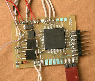
Completion of the next sonar board using 168Mhz ARM revealed some interesting nuggets about the STM32.

It works with only 1 VCAP, VDD, & VSS connected, greatly simplifying the routing.  The VDDA & VREF+ can be connected to a VDD pin.  Only 1 VSS is required.

ADC sampling can go in the 600khz range with no obvious noise issues like the PIC.  8 bit sampling goes a lot faster than 12 bit.  While it can do a lot more with audio than video, it's still very limited in the 300khz range that you need for sonar, so you'll be hand optimizing.

Function calls kill it.  As much as possible must be inlined.  Those convenient GetFlagStatus calls need to be replaced with inline ->SR calls.

Some operations go a lot faster with unsigned than signed variables.  1 operation that signing killed involved multiply & divide.

The packing order of variables affects speed.  Splitting up a bunch of frequently used variables with large, infrequently used buffers slows it way down.  Having all the frequently used variables together speeds it up.  It's a caching issue.


sonar95.png


So with the ARM screaming at 329khz per channel, that was propagation delay with the sensors 3" apart & the transmitters 2ft away, on the bench.

sonar96.png


That was the propagation delay over 10 ft with 3 sensors.  That actually looks equivalent to the PIC sampling at 266khz.  1 of the sensors has 4x the gain of the other 2, without showing any obvious difference.

sonar97.png


The position calculation in centimeters once again lost a lot of precision.  With the 12V emitter & super fast sampling, it was almost omnidirectional, but the precision dropped as the horizontal distance increased.  This was the 1st time horizontal accuracy was seen improving dramatically with wider sensor spacing.


The pings were 8 Hz.  The sampling rate was 329khz at 8 bits.  There's no point to using the 256khz radio bandwidth.


Calculating the position has been done with very slow, trial & error pythagorean calculations on the ARM.   Despite its floating point support, there hasn't been enough incentive to load the math library on the flash, to do a fast trig solution.

The position is only calculated on the ARM in case it could be sold as a standalone position calculator.

Ground based sonar still isn't going to have the all out range that ground based vision could have.  For 1 vehicle flying in a small room, it might have the immunity to the environment to come out ahead of vision.  It's not as compact as an equatorial mounted camera, but has a lot less fabrication & costs a lot less.  It won't need a high speed connection to the computer.


In Feb 2010, an amazing amount of work went into getting Marcy 1 a sonar guided autopilot, in the belief that the real M.M. would have seen it in person.  It turned out Her attention was impossible to get for any normal guy & there wasn't a snowball's chance in hell of Her ever watching a normal guy fly a UAV.

Even if sonar worked in time, it was an obsurd campaign.  She had many celebrity suitors & is now settled down with a famous producer in LA, resigning from the USAF in 3 years.  In that case, it would have been truly awful for Her if the sonar panned out in time.

Read more…

 3689468868?profile=original

Had a pretty traumatic experience today while I was trying to get an APM 2.0 working on an RTF "trainer," when I turned off the transmitter and the ESC burst into flames. I was hoping the community might be able to point me in the direction of a solution.

I was ground-testing an electric RC (a Hobbico NexStar electric) with an APM 2.0. The APM was completely stock, and had been loaded with firmware from the Mission Planner without any modification. Controls were calibrated on the Mission Planner as instructed in the wiki, with CH5 on the transmitter dedicated to switching between manual and "stabilize." This was using a Futaba 6ch controller.

The jumper was connected on JP1, in the stock configuration on the APM 2.0. I was supplying power to the output rail via 4.8v NiCd power source, which I checked beforehand actually was supplying about 5V. A standard feature of this trainer-style airplane, an external on/off switch was between the power source and the output rail. The 50A ESC used in the RC airplane did not have a BEC. A previous test without APM 2.0 proved the servos, ESC, motor, RX and TX were all working as designed.

With the APM installed in the airframe and connectors attached as per the wiki, I turned on the transmitter and then the power source to the APM. In manual mode, all controls responded to inputs as was expected. I switched CH5 to "stabilize," and servos and control surfaces responded to yaw, pitch and roll, albeit in the reverse, and potentially with not enough input (I chalked this up to a calibration issue I hoped to resolve after shutting everything down).

I switched CH5 on the transmitter (CH8 on the APM 2.0 input rail) back to "manual," and then turned off the transmitter. The motor turned quickly as if responding to input, then stopped, and smoke rolled out of the electronics bay, followed promptly by a fire coming from the ESC. This fire got approximately 6 inches tall from the ESC and began to burn away the aircraft's external coating and lighted the wood frame of the fuselage. I yelled to my wife to run and get the fire extinguisher, which she ripped off the wall and passed to me, and I applied the extinguisher directly to the electronics bay. This put out the flame and saved the house, and I carried out the airplane to the back yard for safety. By this time, there was no more smoke.

An inspection after the fire showed that a section of external coating was burned, as was some of the balsa frame. Several wires leading to the ESC (two motor wires and battery positive wire) were melted right through. Although the LiPo batteries were mounted next to where the fire took place, they appeared at least on visual inspection to be unharmed by the fire. APM and receiver seemed unharmed from a visual inspection, but I'm not certain at this time whether the chemical flame retardant from the extinguisher has altered the function of those electronics.

At this point, I'm real hesitant to test this particular APM 2.0 on a new ESC to investigate the problem, and I'm really concerned about this as a safety issue. Does anyone know of a condition whereby the autopilot would supply max current to the ESC if the connection between TX and RX is severed? Thank you.


Specs:

TX: Futaba 6EXA 6ch
RX: Futaba R168DF
ESC: Hobbico SS-50D 50A (w/o BEC)
Motor: RimFireTM 42-50-800 Outrunner Brushless Motor

More pics:

3689468643?profile=originalLeft side of aircraft, showing damage to external coating.

3689468847?profile=originalElectronics bay shortly after the event. In front are dual LiPo batteries, wrapped in protective foam. The 4.8v RX/APM power source can be seen hanging over the edge of the aircraft on the right of the photo. Yellow residue is flame supressant.

3689468910?profile=original

A shot of the APM and RX upon extraction. Both were coated in a thick layer of frame suppressing powder, until some of it was vacuumed off.

Read more…

Quad Copter Mountain Sufing

Since we've got our own quad platform mountain we're slowly starting to progress further into mountains. The neat thing about quads: You can really "interact" with people. Great fun :)

Read more…

Running an autopilot on Android

3689468737?profile=original

Here's a fun little project I've been working on for ~6 months now.  It started when I looked at my phone and thought this has everything needed for an autopilot - 3-axis gyros, accelerometers, magnetometers, GPS, fast CPU, plus a nice big touch screen and more wireless modems than you can point a stick at.  The only problems are (1) it's a multitasking operating system, not real-time; and (2) needs extra hardware to drive servos and switch between manual and auto control.

I solved the first problem by buying a used Samsung Nexus S with a faulty screen (discolouration) on ebay for $80, installing a stable, bare-bones version of android 2.3, rooting it, and disabling CPU throttling.  50Hz servo update loops and 110Hz sampling loops are no problem - timing is reliable and it only uses ~5% CPU (using floating point everywhere and some bloaty object-oriented code). 

Second problem was solved like this:

3689468686?profile=originalThe Ardupilot legacy board doesn't actually run any ardupilot code - it's just a convenient and cheap way to get an Arduino and a multiplexer.  It just takes servo commands from the phone and uses the Arduino servo library code to drive the servos.  Most of its time is spent sampling the baro sensor.  It samples at around 20kHz, and using 4096x oversampling I get 4 16-bit samples per second with an altitude resolution of around 15cm and noise of about +/- 30cm.  The bluetooth link looks scary but works fine.  It's done about 10 hours of autonomous flight with no issues, and only drops out if I take the phone at least 10 meters away from the plane. 

Waypoints are selected on a google map interface:

3689468765?profile=originalGains etc can be easily adjusted:

3689468808?profile=original
And, of course, a flight video:

Behind the scenes it runs the DCM + complimentary filter code.  I've added some extra features over the last few months:

Autonomous thermaling (works well in warmer weather)

Hardware in loop simulation with X-Plane and MS FSX over WiFi

Wind and airspeed estimation

Dead reckoning (using gyros/magnetometer and estimated speed - can work through short GPS dropouts)

Android-to-Android Telemetry over WiFi or mobile internet (later requires sim with public IP - hard to find)

Features I plan to add:

Waypoint addition/modification from Android groundstation (if/when I can convince a telco to give me public IPs)

Fly-by-wire(less) over mobile internet (ditto)

Photo/video taking at specified locations with onboard camera (will require mounting under wing)

I'll post about some of these over the next few weeks.

Read more…


We've had dataflash card issues with one of our APM2's since day one, but our second APM2 worked fine until after a few rough landings (no repairs were needed, so they weren't that bad), we can't get the mission planner to identify logs or the APM2 to create them, not sure which.

We tried reformatting the card, removing it and reinstalling it, updating the firmware on the APM2 and the Mission Planner version, etc, but to no avail.

We're moving forward with FPV & Telemetry while we figure it out, but we'd really like to have it working... any suggestions?

Thanks!

Read more…

Waterloop

Try to do this with your quad! The cup is not attached.  If you pay close attention to the cup, you'll notice it sliding back and forth during maneuvers.  That's just too cool!

Jago Svensson is a talented aerial photographer and all around tinkerer.  I'm sure you'll also enjoy checking out his website here:  http://jago.se/jago.se/Projects/Projects.html

I really like his folding quad concept.

Read more…

Getting ready for AUVSI

3689468521?profile=original

We're getting our booth ready for AUVSI and I thought some of the people on DIY Drones might appreciate a sneak preview of the helicopter that we'll be showing off. I was really hoping to have some dead bugs on the rotors before AUVSI, but some of the machined parts got delayed. So, first flight will have to wait until we get back home!

Here's the SA-200 Weasel in the paint booth :-)

Read more…

My First Quad


3689468503?profile=original
I decided recently after getting a chance to operate an Aeryon Scout that I would like to have a Quad UAS of my own. I have started my build of an H-Quad. The same design that was posted recently from  FliteTest.com. It looked to be an easy frame to build and is essentially a X-formation Quad. Here are the preliminary photos and a list of parts. Since this is my first Quad build I would love to get as much input as possible. Thanks

Frame: Scratch Built H-Quad Frame

Motors: Turnigy D2836/11 750KV Brushless

ESC: Hobbyking SS Series 35-40 Amp ESC w/ 3 Amp BEC

Prop: x2 CC 11x4.7 and x2 CW 11x4.7

APM: APM 2.0 running Current ArduCopter Firmware.

Here are some pictures of th
e frame.3689468345?profile=original

3689468554?profile=original

Read more…