All Posts (14033)

Sort by

More and more government drone pilot and technician jobs are being advertised. If you are a school or training institution, you may wish to commission a build by people who are already supplying government drones. But what about the costs you say? Like many things, it depends on what you want, who you know and how charming you are. If you are a pilot, mechanic, school, startup or government agency on a tight budget, you can still look sleek and dominate at a fraction of the usual cost.

Airframes somewhat similar to these can be commissioned surprisingly cheaply. They look the part on the ground and in the air. There is ample space for telematics and avionics. If you are a designer and manufacturer of these electronic devices, having a test platform that looks the part can make all the difference when it comes to closing sales.

o, who can help with this and more? Tommy! Tommy owns TMMY Scale Composites in Lamphung, Thailand. Lamphung is a short drive or train ride from serene and picturesque Chiang Mai. Tommy’s first question will be which airfoil do you want? 

Should you want to train or train others on a platform that looks big bureaucracy without breaking the bank, contact Tommy at: Tmmy Scale Composite

266 Mu1 T.Muang NGA A.muang
Lamphun Thailand 51000
Tel. +6681 344-1534
Email: tmmyscalecompt@gmail.com

Website: https://tmmy.pantown.com/

Read more…

DS600

DS600 is made from reinforced carbon fiber. “H”design makes it stronger and durable. It equips with T-motor

505-S propulsion system to improve the efficiency and endurance. The foldable propeller and landing gear make

the drone easy to carry. DS600 is perfect for long range inspection, surveillance and mapping.


  • Wheelbase: 600MM
  • Dimension: 600mmX600mmX 300mm
  • RTF weight(no battery): 2.5KG
  • Max payload : 2KG
  • Max take-off weight : 6KG
  • Working altitude : 1-500m
  • Flying speed : 1-15m/s
  • Endurance: 40-60min

9032360300?profile=RESIZE_710x


9032362088?profile=RESIZE_710x

9032361494?profile=RESIZE_710x


Read more…

ArduRover Skid Steering

Hi, I'm building ArduRover with Skid Steering, The platform are base of DFROBOT Pirate 4WD and using 2 DC Motor L298N

8997855656?profile=RESIZE_710x


I'm using the firmare for Pixhawk 1 (fmuv3)

4.0.0-FIRMWARE_VERSION_TYPE_OFFICIAL

and according the ardupilot docs for Rover
My config for CH1 and CH 3 are

For “Skid steering” vehicles (like R2D2) these parameters values will need to be set:

Actualy its depend on your wiring setup at L298N for direction

8997883685?profile=RESIZE_710x

Here is the schematic of how I wiring it.

8997885267?profile=RESIZE_710x

The ENA and ENB jumper was remove.

For skid-steering vehicles like the Pirate 4WD from DFROBOT
Set MOT_PWM_TYPE = 3

8997896266?profile=RESIZE_710x

In my transmitter when throttle is zero the the ch1 push left a quarter, it will rotate the rover to left (left wheel stop - right wheel move) and also the opposite. But if push full it will move fast forward.

If the ch 3 push half more (55%) it will move forward slowly. I'm still setup some parameters for smooth moving.


Read more…
100KM

An In-depth Comparison Of Mapping Drones

When acquiring a mapping or surveying drone, the choice is quickly narrowed to a fixed-wing airplane combined with Vertical Takeoff and Landing (VTOL) for its vastly greater range, versatility and ease of use. Within this segment, there are several commercial-grade solutions of European origin. But comparing their capabilities and limitations can be difficult.

The following comparison was made to provide a detailed insight into the characteristics of the leading suppliers in this field. The data has been verified across multiple sources. Several aspects have been calculated to provide a consistent representation of the data. The calculation methods and sources are provided at the bottom of this article.

The platforms chosen for this comparison are:

  • The DeltaQuad Pro #MAP by Vertical Technologies
  • The WingtraOne by Wingtra
  • The Trinity F90+ by Quantum Systems
  • The Marlyn by AtmosUAV
  • The eBee X by SenseFly 

In this article, you will find an abstract of the comparison.
Click here to read the full comparison


Key Features

A quick rundown of the most critical aspects that are relevant to mapping.

  • Max flight time is calculated at sea level with camera payload.
  • The coverage is calculated by multiplying the maximum flight distance by the maximum camera resolution. It is based on 3CM per pixel with an overlap of 50%.
  • To compare pricing a package was selected for each model that most closely resembles: 42MP camera, <1CM PPK, 2 Batteries, Standard radio, GCS (if available).


I7Pk5njH6FJe4FpJV5Wuti2qnmYXz4erpMIu3LeuuVZvA_4clCTqZvprnFWYT-eFT9vKo0dLPlJaL27JrgAIpnwGnHTk72tHOcB_38huIC9FYRf09Gx0RqHZ5u-ztQ4QsHwQGXEX

Maximum surveying area in Hectares

The maximum area that can be mapped in a single flight is determined by several factors such as camera resolution, cruise speed, endurance, and lens options.
This comparison is based on the highest resolution offered for each platform, combined with the maximum flight distance. The values have been calculated based on 3cm per pixel resolution and a 50% image overlap. The values have then been compensated to account for the camera’s minimum trigger interval.
 

Maximum telemetry range

The maximum range at which the UAV can be controlled. Long-range communications is important for corridor-type surveys such as power lines, pipelines, railways, and roads.

The indicated ranges are the maximum radio range as specified by the supplier. Nominal ranges can be lower.


Maximum image resolution

The maximum image resolution in Megapixels is the total number of pixels that make up a single image. This can be an important factor for a fixed-wing/VTOL UAV.

A higher resolution allows:

  • Covering larger areas
  • Flying at higher altitudes
  • Producing higher resolution end results
  • Better post-processing performance with more accuracy
 

Maximum flight time

The maximum flight time for fixed-wing UAV depends on the altitude above sea level. As the altitude increases, the UAVs need to fly faster due to a lower air density. However, the lower air density also provides less drag, therefore in most cases, the maximum flight distance remains the same at all altitudes.


The indicated maximum flight times are at sea level while carrying a regular camera payload.


Read the full comparison

The full comparison contains detailed technical specifications, pricing details, sources, and methods of calculation.
Click here to read the full comparison

Read more…

IDIPLOYER MP2.1, an extremely lightweight, feature-packed and affordable drone docking-station. It has been designed and built by idroneimages, based out of Reading, England, to enable fully autonomous drone operations. Integrated with their proprietary contact-charging system and the powerful FlytNow Auto software, the IDIPLOYER MP2.1 is an obvious choice for drone service providers and businesses alike.

With their intensive and iterative efforts, the engineers at idroneimages provide groundbreaking features to the market, including: 

  • Lightweight enclosure: Weighing just 23 kg (50 lbs), the IDIPLOYER MP2.1 offers increased portability, which eases shipping to anywhere across the world and supports easy installations, on building rooftops and vehicles
  • Autonomous contact-based charging: From 15% to 100% battery charge within 50 minutes without employing complex robotics or battery cell modifications, thereby reducing mechanical complexity and increasing reliability
  • Precision landing: Computer-vision-aided technology for automatic drone landings with 99.99% accuracy; includes additional rollers for robust performance
  • Weatherproof design: Designed based on IP65 standards to withstand harsh environment; comes with thermostatic heating & peltier cooling capabilities for extreme temperature control

The ongoing pandemic has forced businesses to rethink their approach towards deploying automated systems, as they have now become more of a necessity than a mere nice-to-have. With the IDIPLOYER MP2.1, idroneimages presents a turnkey solution to the market that is both affordable and accessible. This widens the scope for businesses to deploy fully automated drones in several areas, such as aerial monitoring, progress tracking, security, and incident response.

Place and Time

Join the FlytBase and idroneimages teams this Friday, 21 May, at 11:00 CST, as they take you through the journey of this feature-rich drone-nest from ideation to production. The event will be live-streamed for worldwide access. Register now at https://flytnow.com/flytlaunch/idiployer/ and stand the chance to win some exciting prizes!

Some local timezones for your quick reference:

  • London: 17:00 BST
  • San Francisco: 09:00 PDT
  • New York: 12:00 EST
  • Berlin: 18:00 CEST
  • Abu Dhabi: 20:00 GST
  • New Delhi: 21:30 IST

How to Register

Registration is free and as simple as a few clicks! Follow this link and sign yourself up. Registrants gain exclusive access to a giveaway for a limited time!

Save your seat for the big day and you could be a part of the FlytNow Preferred Partner program, with access to our wide marketing collateral, rich global network, and strong digital presence!

Reserve your spot here: https://flytnow.com/flytlaunch/idiployer/

About idroneimages

idroneimages was founded in 2018 by a group of like-minded drone enthusiasts who wanted to demonstrate the transformational capabilities of drones in business operations. From safety to detailed inspection imagery, drones have been integrated with industries such as agriculture and wind energy. Today, idroneimages operates some of the most complex and highly functional drones in the market, adapting them to its clients' needs and specific requirements.

Read more…

Lithium Ion battery Pack designer utility

8922509889?profile=RESIZE_710x

Lithium ion batteries have a higher energy capacity than Lithium Polymer packs, in general. Higher capacity lithium ion packs can be designed if the current draw of the drones are known. We have built a web utility to find the right chemistry of cells to use, from among the hundreds of different cells. 

Input the max weight, and current discharge of the drone and see: 

  • Battery cell configuration (number of cells in parallel and series) 
  • Approximate flight time as compared to current aircraft (without weight change)
  • Battery weight.

Reach out to us shout@rotoye.com to get free access to this utility. 

Read more…

3D printed truck

8910822072?profile=RESIZE_710x


8910913878?profile=RESIZE_710x

The high cost of good RC truck kits, diminishing need for such kits & the noise of gearboxes made me look elsewhere for a robot platform.  3D printing a truck from scratch, with only a few metal parts still being off the shelf, was the next step.  The only parts which have to be outsourced are the motors, steering servo, & steering knuckles.  Everything else is 3D printed or home made electronicals.  The size was based on the original Tamiya lunchbox.


8910820663?profile=RESIZE_710x


8910862088?profile=RESIZE_710x


8910842477?profile=RESIZE_710x


8910853293?profile=RESIZE_710x


The remote control is a single paw 3 channel, with 100mW radio, ball point pen springs, hall effect sensors.


8910905662?profile=RESIZE_710x


8910905683?profile=RESIZE_710x


The remote control is charged inductively.


8910864885?profile=RESIZE_710x


8910868496?profile=RESIZE_710x


Motors are direct drive Propdrive 4248's of any KV rewound with 20 turns of 26AWG.   They don't produce enough torque to go up hills.  The motor sensor is a dual hall effect sensor resolver.  

The main problem is cooling the motors while getting more torque.  Metal motor mounts of the right shape continue to be cost prohibitive & PLA doesn't dissipate heat.


8910880482?profile=RESIZE_710x


8910880691?profile=RESIZE_710x


Electronicals automate just enough to drive it with 1 paw, but not so much that it's never finished.


8910883454?profile=RESIZE_710x


8910883474?profile=RESIZE_710x


8910883694?profile=RESIZE_710x


8910886053?profile=RESIZE_710x


8910886455?profile=RESIZE_710x


Traction & steering are 2 separate modules.  Steering uses a brushless servo with stock lunchbox servo saver.


8910884879?profile=RESIZE_710x


Motors are powered by L6234's mounted dead bug style to get the heat out.

8910890092?profile=RESIZE_710x


8910890477?profile=RESIZE_710x


Tires are printed out of TPU in varying shapes to adjust hardness & traction.


8910891284?profile=RESIZE_710x


8910895474?profile=RESIZE_710x


Rear tires have a flat wide shape for more forwards traction.  Front tires have a round shape for more sideways traction.


8910909092?profile=RESIZE_710x


The battery is completely enclosed.


Read more…

8904271867?profile=RESIZE_710x


Great post from NASA explaining how the Mars helicopter autopilot works:

----

Before each of Ingenuity’s test flights, we upload instructions that describe precisely what the flight should look like. But when it comes time to fly, the helicopter is on its own and relies on a set of flight control algorithms that we developed here on Earth before Ingenuity was even launched to Mars.

To develop those algorithms, we performed detailed modeling and computer simulation in order to understand how a helicopter would behave in a Martian environment.  We followed that up with testing in a massive 25-meter-tall, 7.5-meter-diameter vacuum chamber here at JPL where we replicate the Martian atmosphere. But in all of that work, we could only approximate certain aspects of the environment. Now that Ingenuity is actually flying at Mars, we can begin to assess how things stack up against expectations. Here are some key aspects of the flight control system’s performance on Mars.

Takeoff

Unlike many consumer drones, Ingenuity is not controlled by changing the rotor speeds. Instead, we control our Mars Helicopter in the same manner as full-scale terrestrial helicopters: by changing the pitch angle of the blades, which affects the airfoil “angle of attack” and thereby determines how big a “bite” the blades take out of the air. The bigger the bite, the more lift (and drag) is produced. Like a traditional helicopter, we can change the pitch angle in two ways: by using “collective control,” which changes the blade pitch uniformly over the entire rotation of the blade, and by using “cyclic control,” which pitches the blade up on one side of the vehicle and down on the other.

When Ingenuity takes off, the rotor is already spinning at the setpoint speed of 2,537 rpm. We take off with a sudden increase in collective control on both rotors, which causes the vehicle to “boost” off the ground. During this initial takeoff phase, we limit the control system to respond only to angular rates (how quickly the helicopter rotates or tilts). The reason for this is that we don’t want the control system to be fighting against the ground, possibly resulting in undefined behavior.

The initial takeoff phase lasts for only a split second; once the helicopter has climbed a mere 5 centimeters, the system asserts full control over the helicopter’s position, velocity, and attitude. At this point we’re accelerating toward a vertical climb rate of 1 meter per second.

To estimate our movements during flight, we use a set of sensors that include a laser rangefinder (for measuring altitude) and a camera. We don’t use those sensors until we reach 1 meter altitude out of concern that they might be obscured by dust near the ground. Instead, we initially rely only on an inertial measurement unit (IMU) that measures accelerations and angular rates, and we integrate those measurements to estimate our movements. This is a type of “dead reckoning” navigation – comparable to measuring how far you’ve walked by counting your steps. It’s not very accurate in the long run, but because Ingenuity takes only a couple of seconds to reach 1 meter, we can make it work.


Ingenuity's Rotor Power During Flight Two Ingenuity’s rotor power during Flight Two. Credits: NASA/JPL-Caltech. Download image ›

One of the things we were curious about is how “confidently” Ingenuity would boost off the ground and reach that first threshold of 5 cm. Data from the first three flights shows that portion of the climb took about 0.25 seconds, which is very much in line with expectations and indicates that Ingenuity had no issue producing enough thrust on takeoff. During this initial boost, we expected to see a spike in the power required by the rotor system, and that is indeed what we observed. For example, the spike in Flight Two was about 310 watts (W) – well below the maximum capacity of our batteries, which can tolerate spikes as high as 510 W.


Ingenuity Flight Two 
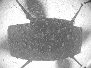
Ingenuity Flight Two: A picture from the navigation camera aboard Ingenuity captured the helicopter on takeoff during Flight Two, showing little sign of dust. Credits: NASA/JPL-Caltech. Download image ›

After takeoff, Ingenuity took about 2 seconds to reach the 1-meter altitude where it could start using its full suite of sensors. That being said, while we did see some faint dust in the images taken by the Perseverance rover (parked nearby) on takeoff, there was no indication flying dust or sand obscured the altimeter or camera, so our design appears to have erred on the cautious side in this regard (which is a good thing).


The moment the helicopter’s legs leave the ground, its motion starts to become affected by wind. These winds can cause the vehicle to momentarily roll (side to side) or pitch (forward or backward) on takeoff, until it has time to catch and correct itself. We were prepared for some significant roll/pitch angles on takeoff if winds were high at the ground level, but in Ingenuity’s three takeoffs so far, they have been limited to a couple of degrees only, making for nice, vertical takeoffs.

Hover


Ingenuity's Horizontal Position During Flight One Hover 
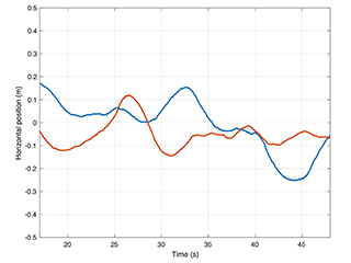
Ingenuity’s horizontal position relative to start during Flight One hover. Credits: NASA/JPL-Caltech. Download image ›

During hover phases of flight, we are attempting to maintain a constant altitude, heading, and position. In evaluating how well we are managing to achieve that, we are forced, for the most part, to rely on Ingenuity’s own estimates of what it was doing, as we have limited data establishing “ground truth.” Those estimates are subject to errors in navigation that will be covered in a separate post. But the steadiness of these estimates tells us a lot about how tightly the controller is able to hold the desired values. 


The data shows that we hold our altitude extremely well in hover, to within approximately 1 cm. We also hold the heading (which way we point) to within less than 1.5 degrees. For horizontal position, we’ve seen variations up to approximately 25 cm. Such variations are expected as the result of wind gusts.

So, what has the wind been like during our flights? Fortunately for us, the Perseverance rover carries the MEDA weather station. For Flight One, we have measurements from MEDA indicating winds of 4-6 meters per second from the east and southeast during most of the flight, gusting to 8 meters per second. Keep in mind that those measurements are made 1.5 meters above ground level, and the tendency is for winds to increase as you go from ground level up. We also have atmospheric density measurements at the time of Flight One, showing 0.0165 kilograms per cubic meter, or about 1.3% of Earth’s density at sea level. Using this information, we can assess the system’s performance in another important respect – namely, the control effort required to fly.


Ingenuity's Collective Control During Flight One 
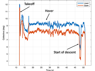
Ingenuity’s collective control during Flight One. Credits: NASA/JPL-Caltech. Download image ›

For the collective control (remember, that is the one that changes rotor blade pitch angle uniformly to affect helicopter’s thrust), we would like to see hover values roughly consistent with prior expectations. During Flight One, we hovered with around 9.2 degrees collective on the lower rotor and 8.2-degree collective on the upper (that’s the angle of the blade’s “chord line” – an imaginary line drawn from the leading edge to the trailing edge of the rotor blade – at ¾ of the rotor radius). Those values are 0.7-0.8 degrees lower than the trim values we anticipated (9.0 degree on the upper rotor and 9.9 degree on the lower rotor). But those trim values were tuned based on tests without wind at a somewhat different density/rotor speed combination, so this difference is not unexpected. Another indication that we are within our aerodynamic comfort zone is the electrical rotor power of around 210 W in hover, which is also right in the vicinity of what was expected. Taken together, the results indicate that we have good margin against “aerodynamic stall,” which is when the blade airfoil’s angle relative to the surrounding airflow is increased beyond the point where it can produce further increases in lift.


Ingenuity's Lower Cyclic Control on Flight One 
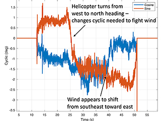
Ingenuity’s lower cyclic control on Flight One. Similar cyclic controls applied on the upper rotor. Credits: NASA/JPL-Caltech. Download image ›

We also evaluate the cyclic control, which is used to create roll and pitch moments on the vehicle. We have seen relatively steady values in hover, generally of magnitude less than 3 degrees, which leaves ample margin against the upper limit of 10 degrees. The cyclic control inputs tell us a fair amount about the wind that the vehicle has to fight against. For example, for Flight One the cyclic control is consistent with winds from the east and southeast, which is in alignment with MEDA observations. The cyclic control effort also increases with altitude, which indicates that winds are getting higher further from the ground.


Landing

Landing is a particularly challenging part of any flight. Ingenuity lands by flying directly toward the ground and detecting when touchdown happens, but a number of events occur in rapid succession leading to touchdown. First, a steady descent rate of 1 meter per second is established. Then, once the vehicle estimates that the legs are within 1 meter of the ground, the algorithms stop using the navigation camera and altimeter for estimation, relying on the IMU in the same way as on takeoff. As with takeoff, this avoids dust obscuration, but it also serves another purpose -- by relying only on the IMU, we expect to have a very smooth and continuous estimate of our vertical velocity, which is important in order to avoid detecting touchdown prematurely.

About half a second after the switch to IMU-only, when the legs are estimated to be within 0.5 meters of the ground, the touchdown detection is armed. Ingenuity will now consider touchdown to have occurred as soon as the descent velocity drops by 25 centimeters per second or more. Once Ingenuity meets the ground, that drop in descent velocity happens rapidly. At that point, the flight control system stops trying to control the motion of the helicopter and commands the collective control to the lowest possible blade pitch in order to produce close to zero thrust. The system then waits 3 seconds to ensure the helicopter has settled on the ground before spinning down the rotors.

People have asked why we contact the ground at the relatively high speed of 1 meter per second. There are multiple reasons for this. First, it reduces the dead-reckoning time that we need to spend without using the camera and altimeter; second, it reduces the time spent in “ground effect,” where the vehicle dynamics are less well-characterized; and third, it makes it easier to detect that we’ve touched down (because the velocity change is clearly sufficient for detection). What makes this strategy possible is the landing gear design which helps prevent the vehicle from bouncing on landing.


Ingenuity's Estimate of Vertical Velocity During Flight Two 
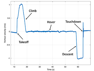
Ingenuity’s estimate of vertical velocity during Flight Two. Credits: NASA/JPL-Caltech. Download image ›

Any touchdown detection algorithm of this kind has to strike a balance between two potential pitfalls: (1) detecting touchdown too early (thereby dropping to the ground from the air) and (2) not detecting touchdown soon enough (which would cause the helicopter to keep trying to fly after coming in contact with the ground). Data from Ingenuity’s flights on Mars show that we were not in danger of either of these scenarios. During descent, Ingenuity has maintained its vertical velocity to within approximately 4 cm per second, and it has detected the necessary 25 cm per second drop within approximately 30 milliseconds of touchdown.


As we continue with our flights on Mars, we will keep digging deeper into the data to understand the various subtleties that may exist and would be useful in the design of future aerial explorers. But what we can already say is: Ingenuity has met or exceeded our flight performance expectations.

Read more…
Moderator
 

8876735875?profile=RESIZE_710x

Dear Friends,
1 months ago our cubesat satellite "FEES" release in space by Soyouz 2 . The hardware is based of VRBrain 5 architecture , we put in space a STM32F4 micro controller . The first release don't use Ardupilot , hope the next one with your help and our experience could be . After a lot of test and study about the communication in space we found that lora protocol it's a great option for sat to ground and could be ground to space communication . So actually FEES is still in space and continue to trasmit it's position to earth. Now for recived it we are using global opensource network called TinyGS . Now we start we next step that's is try to constantly comunicate with the sat all around the world . So now we need the help of our great community . We need put small ground station around the world for connect our cubesat at any time of day and night. Fees is only first sat that we have in space but my opinion is that in the future we can add more cubesat and interconnect it and interact. I need other drone enthusiast around the world with ham license for implement ground station and cover ther world. The project is already available in alfa version . I developed a global dashboard where all gs will be available like tinygs , but with our implementation we can also trasmit message to satellite . We try as 12 years ago to implement a version of ardupilot for sat , where Ground station , protocol , and firmware for special future will be developed in the next months . If other guys around the world would help me and other member of this new group in ardupilot are welcome . The ground station is only the starting point , FEES is only the first sat available . Hope that next one will be from our community with Ardupilot code in space !!! 😉 Follow same picture of position of FEES in the space in last month. And a picture of dahboard during first global trasmission with sophyai.space gs . If you need more info or would join our new cool project contact me .. on Ardupilot discord there is a new channel called #satellite
This is the link in Ardupilot discord channel https://discord.gg/SJAxYMHYQp
If you need more info don't exitate to contact me 
 
Last Month trasmission from fees around the world : 
8876737854?profile=RESIZE_710x
 
8876738898?profile=RESIZE_710x
 
Read more…

8875503481?profile=RESIZE_710x

From Applied Aeronautics:

Albatross UAV made its first appearance in 2013 on DIY Drones. The Albatross UAV Project, as it was titled, set out to design a composite UAV that met a long list of precise and ambitious performance metrics. Those were: > 6KG MTOW, plenty of room for sensors and batteries, up to 4 hours of flight time, wide flight envelope, and last but not least, efficiency. Over the span of 13 months, the Albatross began to take shape through meticulous design and testing. To date, our company has Albatross systems flying in over 50 countries and on every continent. Still, it’s important to us to always remember our roots as a company spurred by the passion to create something truly incredible from the ground up.

Read more…

AIRLink stands for Artificial Intelligence & Remote Link. The unit includes cutting-edge drone autopilot, AI mission computer and LTE connectivity unit. Start your enterprise drone operations with AIRLink and reduce the time to market from years and months down to a few weeks.

More info: https://sky-drones.com/airlink

Sky-Drones Technologies hit their 10-year anniversary this year, so to celebrate the occasion the company decided to prolong the launch of their latest addition to the product range. This has been an entire year in the making, excitement has built up, and expectations have been implied, but the team have absolutely not disappointed!

As drones become more and more hardware-defined and software-orientated, Sky-Drones Technologies must be at the forefront of innovation. With that in mind, the company presents UAV industry specialists and enthusiasts alike: AIRLink. The artificial intelligence and remote link unit that is installed to your enterprise UAV to provide:

  1. Cutting edge autopilot: manual and fully autonomous flight capabilities for multirotors, fixed wings and VTOLs
  2. AI Mission Computer: onboard data processing and computer vision
  3. LTE Connectivity: BVLOS flights, Cloud connectivity and remote workflows

What these exceptional elements mean for the UAS industry is the start of a whole new era in UAV flight control, data analytics, and safety. Never has anyone created a product that can withstand such extreme ambient temperatures and high computational power without an overheating issue, a product that has entirely integrated hardware and software for flight and payload data analytics, a product that can be so many products in one or one product with so many cutting-edge capabilities... Until now.

To give an overview, AIRLink comes with a FPV HDR 1080p camera to provide users with a video stream that has exceptional image quality. The unit is constantly connected to the internet, has been designed with critical peripherals as an essential element for user convenience, and has built-in LTE and Wi-Fi. 

The goal with AIRLink is to integrate this all-in-one unit into the UAV designs during the manufacturing stages so as to focus the efforts and resources of the drone itself rather than avionics and connectivity. With that in mind, Sky-Drones offers a variety of options when choosing how to use AIRLink to the best of its ability:

  1. AIRLink OEM – purchase AIRLink as Sky-Drones designed it. Includes all the features and aviation-grade aluminium casing with the heatsink. The process includes simply installing the unit to your UAV.
  2. AIRLink Enterprise – Sky-Drones will provide the internal electronics of the AIRLink units, excluding the casing to reduce the size of the units and integrate them directly into your UAV during the manufacturing process.
  3. Reference Design – build AIRLink yourself in-house! Sky-Drones will provide all the relevant instructions, manufacturing material, and will be on hand for engineering support whilst you set up your operation for manufacturing your own AIRLink units.

Read more…

Hacking a cheap drone to run PX4

8831264061?profile=RESIZE_710x

From Hackaday:

Sometimes bad software is all that is holding good hardware back. [Michael Melchior] wanted to scavenge some motors and propellers for another project, so he bought an inexpensive quadcopter intending to use it for parts. [Michael] was so surprised at the quality of the hardware contained in his $100 drone that he decided to reverse engineer his quadcopter and give the autopilot firmware a serious upgrade.

Upon stripping the drone down, [Michael] found that it came with a flight management unit based on the STM32F405RG, an Inertial Measurement Unit, magnetic compass, barometric pressure sensor, GPS, WiFi radio, camera with tilt, optical flow sensor, and ultrasonic distance sensor, plus batteries and charger! The flight management unit also had unpopulated headers for SWD, and—although the manufacturer’s firmware was protected from reading—write protection hadn’t been enabled, so [Michael] was free to flash his own firmware.

We highly recommend you take a look at [Michael]’s 10 part tour de force of reverse engineering which includes a man-in-the-middle attack with a Raspberry Pi to work out its WiFi communication, porting the open-source autopilot PX4 to the new airframe, and deciphering unknown serial protocols. There are even amusing shenanigans like putting batteries in the oven and freezer to help figure out which registers are used as temperature sensors. He achieves liftoff at the end, and we can’t wait to see what else he’s able to make it do in the future.

Of course, [Michael] is no stranger to hacking imported quadcopters, and if you’re interested in PX4 but want something quieter than a quadcopter, take a look at this autopilot-equipped glider.

Read more…