i recently came across a video of stocking fish with the use of an airplane. Immediately i thought of our dear community. Is it just me or you too think you can do it more effectively with the use of drones? I am not a marine biologist, but from the video above it looks like half of the fish died in this attempt, don't you think? Some guys from YT agree ;)
Anyway, what do you think? Let's say this is a hard to reach terrain, situated few miles from starting point. It would be a medium difficulty challenge to provide a platform for this task, wouldn't it?
For Americans, the number 76 has special significance, since the US Declaration of Independence was signed in 1776 and every hundred years we go crazy with a "Spirit of 76" celebration. For the British, who were on the other side of that historic division, the date is less celebrated. As a dual US/UK citizen I'm a little conflicted about the history, but not when it comes to the number 76. It's a good one -- celebrate!
So I'm delighted to announce that DIY Drones has now hit 76,0000 members. After slowing down a bit last year, traffic is now rising again, and is nearly at 50,000 page views per day. Thanks to all the members whose daily posts and forum discussion makes this site so vibrant.
To celebrate, 3DR has created a special thank-you 20% discount for the DIY Drones community. Enter "DIYD20OFF" at checkout to apply the discount. (It applies to everything except GoPro cameras and the new Enterprise SiteScan products.) One time use per user, and it expires on March 31st, so get in there now!
A powerful companion computer, like Ordoid XU4, can help build many interesting and complex applications on drones, such as, those using computer vision, swarms, cloud-connectivity, AI, machine learning, and more. Even for regular applications, like, aerial surveys, mapping, or photography, having a companion computer can greatly simplify application development and deployment. However, we need a reliable/robust/well-planned framework to make this happen, and keep it scalable/flexible for future drone applications.
We have been building FlytOS to address this need. FlytOS is built on ROS (Robot Operating System), and it helps drone developers exploit the power of linux-based companion computers. The APIs for navigation, configuration, setup, computer-vision, communication are available in C++, Python and ROS, making it extremely easy to build/deploy custom applications. Builtin web-server allows developers to host web-based UIs and connect to remote/mobile devices using RESTful APIs and web-socket connections, with authentication and security. Further, a ROS/Gazebo based simulator has been tightly integrated with FlytOS to allow developers test their applications in simulation, before deploying those on real hardware. Several other features, such as, onboard web-based setup/GCS utility, video streaming utilities, are also included in FlytOS.
Overall FlytOS architecture is shown in the image below:
We are happy to announce the release of initial version of FlytOS. It has been extensively tested at our lab over last few weeks, and we are now inviting more collaborators, contributors and testers to try it out! It can be used with your own hardware setup (recommended setup: Pixhawk + Odroid; feel free to try it with other combinations and submit your results) or with FlytPOD. It is available for download as two options: a debian package (about 20 MBs), or a complete image (about 2 GBs). The instructions for installation of both the options are available in the documentation.
As part of today's 3DR Enterprise announcement with Autodesk, we also announced a new camera coming to Solo. This is the UMC-R10C, which is designed to be deeply integrated and fully controllable by the Solo software stack and companion computer. More details coming ahead of the launch in April.
3D Robotics partners with Sony on a drone that can map the world in 3D
The competition to capture big industrial customers is heating up
By Ben Popper
The drone business is booming, and companies which manufacture these aerial robots are increasingly trying to produce units that can straddle the divide between the consumer and enterprise market. 3D Robotics, one of the biggest US drone makers, announced this morning that it is partnering with Autodesk and Sony to create a high end version of its Solo drone. The new unit can scan a location — a construction site in progress or bridge that needs inspection — and upload a 3D model or map to the cloud from the air, allowing those files to quickly get into the hands of offsite engineers or managers.
Up till now the Solo drone worked with cameras from GoPro. Today it announced that the new Sony UMC-R10C, a camera that will be officially unveiled at NAB in April, will integrate with the enterprise edition of the Solo. That camera allows for far more detailed image capture, pulling hi-res data to the cloud without having to land and remove an SD card. The enterprise edition of the Solo will also come with a Sony tablet preloaded with Autodesk's FORGE software. "The demand is just huge," says Autodesk's Dominique Pouliquen. "There is not a single construction company we work with that does not have a UAV initiative."
Along with the new Sony camera, 3D Robotics says it is planning to introduce a multispectral and thermal camera, hardware specialized for scanning agricultural sites, chemical plants, and oil rigs.
Autodesk has been moving into the drone industry for a while. Last year it invested in SkyCatch, another company which has been using drones to create 3D maps of construction sites in real time, maps which are then used to guide robotic bulldozers. SkyCatch is currently focused on building its business in Japan, where regulations around commercial use of drones are much lighter, and where demographic trends have created a shortage of human workers.
WILL DJI'S DOMINANCE LAST?
DJI is dominating among the drones used by companies which have filed commercial exemptions in the US and it recently introduced a unit designed specifically for crop spraying. But "it's still very early days, and we're number two [in commercial exemptions]," argues Chris Anderson, 3D Robotics co-founder and CEO.
Anderson believes that DJI's lead on the commercial side is an extension of its consumer dominance, and that this advantage will fade as the enterprise market matures. "So far it's mostly consumer vehicles being used in a commercial context. There are very few large scale enterprise deployments, and the whole workflow has not been touched. The Solo is the first example of an enterprise drone that is integrated from end to end, from drone to camera to cloud."
The real power of the Solo platform is in the software, and we've been hinting since the start that the consumer applications for Solo were just the start. So I'm delighted to announce the official start of the 3DR Enterprise era with SiteScan, our collaboration with Autodesk to use the 3DR Solo and software stack in combination with Autodesk's cloud to create a one-touch "reality capture" from the air.
Leading drone maker, 3D Robotics is teaming up with Autodesk
“Capturing site data today is costly, time consuming, and often dangerous. Drones can easily go where it’s inefficient or unsafe for field personnel, making it easier to accurately measure our world so we can better manage it,” says Chris Anderson, CEO of leading drone maker 3D Robotics.
3D Robotics (3DR) is using Autodesk’s Forge Platform to develop a new UAV-to-cloud solution for enterprise field professionals within the construction, telecom, survey, mapping, energy and infrastructure industries. The Forge platform consists of a set of Autodesk cloud services, APIs, and SDKs for developers to quickly create the data, apps, experiences, and services that power the future of making things.
Anderson describes that by leveraging the Forge platform, 3D Robotics is able to deliver “a complete solution for site capture that will help business customers save time and money and will take humans out of harm’s way.”
3DR is using Autodesk’s ReCap Photo Web application programming interface (API) to develop a reality capture solution that allows field professionals to quickly and easily perform inspections, surveys and scans of work sites from its unmanned aerial vehicles (UAVs). For example, take telecom inspections that involve climbing tall towers. 3DR’s SOLO drone will capture data, then process it in the cloud using Autodesk ReCap, eliminating the need for personnel to risk injury.
Once boundary is drawn around the area selected in Site Scan app, 3DR’s SOLO drone will be ready to take off with one swipe to start the motor and another to take off.
Once processed by the Autodesk ReCap engine, the reality data (3D point cloud, 2D orthographic views, 3D mesh) is made available on A360, an Autodesk cloud platform, from where it can be downloaded to be used by Autodesk software to help field professionals with monitoring sites, measuring stock piles, getting the as-built context, survey and mapping, and more.
After data is collected and stored in the cloud Autodesk software helps with monitoring sites, measuring stock piles, getting the as-built context, survey and mapping, and more.
“We are excited to collaborate with 3D Robotics to help field service professionals collect information and make insightful decisions across a variety of industries,” said Amar Hanspal, senior vice president, Products at Autodesk. “From the integration of Site Scan and Autodesk cloud services, to their use of the Forge platform, 3D Robotics is opening up new ways of working for our architecture, engineering and construction customers.”
Posted by Andrew Ocejo on March 6, 2016 at 11:30am
What you will need:
-2x Ubiquiti Loco M5 NanoStations ($140 on amazon.com) -1x Tx/Rx Kit, Jtech-Digital , or Distancer, HDMI to ethernet over IP ($120-$140 on amazon.com) DIY List: -2x Power step up modules. -2x Power step down modules. -2x POE (Power Over Ethernet) Injectors.(If you are clever, you can make your own with ethernet keystone jacks) -2x 1ft Cat5e or Cat6 ethernet wire. -1x 3ft+ Cat5e or Cat6 ethernet from programing. -2x JST Plug Pair. 5v Out. -1x Deans or preferred connector main for Input Voltage. -1x Ozone Drones Plastic Parts ($24.99, optional).Amazon
OR Ozone Drones offers a starter kit(Optional): -1x Ozone Drones Starter Kit ($59.99, optional, but includes contents of DIY list).Amazon -Volt meter -Knowledge on how to solder, and understanding of basic circuits. -Knowledge on how to use a PC and understanding of basic networking. -Knowledge on basic Wireless Networking.
I have been dying for a cheap solution to feed HD video to my groundstation, without having to spend thousands of dollars. So I set out to figure it out, and these are my findings. Let me know if I should spend the time to make a video to smooth out the processes.
In this DIY, I will be showing you how to build an in budget, very low latency HDMI video Transmitter and Receiver. This video transmission system will transmit back resolutions up to 1080p at 60fps. And will cost under $300 USD to construct. One huge advantage this system has, is it’s almost completely open source putting you in control of the endless possible configurations and add-ons. I will be showing other configurations in later discussions. Ozone Drones makes a few kits, that make this process little easier. The Plastic parts kits includes housings that will help you get things lighter for flight. They also offer a starter kit with the basic necessary components as which is included in the plastic parts kit. If you rather just pay, Ozone Drones offers completely assembled HDMI, Tx, Rx kit for $599 Amazon assembled in the USA. and is still much cheaper then the competition. The plastic parts kit which was designed, manufactured, and the pre-built kits are assembled, in Massachusetts. Please visit www.ozonedrones.com/portfolio for more info. Also Reference figure A
3D Printer Friendly Notice Ozone drones contributes to the open source community, The .stl files for all plastic components will be available to download for the cost of FREE for those of you who own machines capable of manufacturing these parts. Of course you will have to source the hardware! 5x M2-6mm and 6X M2-8mm self taping screws. Please visit: www.ozonedrones.com/downloads
Warnings I can not be held liable for misuse of this of this downlink, and remember FlySafe. Also keep in mind essentially this is a hack of existing products, disassembly and modifications to these products will likely void warranties. We will be mainly soldering, but some desoldering basic components as well! This DIY may not be for the faint hearted.
Terminology: airOS: Ubiquiti proprietary airMax device firmware, and setting software. airMax: Technology used for receiving, and transmitting packets between Ubiquiti airMax radio’s. MJPEG: Motion-jpeg also known as M-JPEG. Video Compression method to allow to stream video over IP. H.264: Another type if video compression, requires less bandwith, but requires more processing power to encode. In most cases hardware is more expensive. POE: Power Over Ethernet. LAN: Local Area Network LoS: Line of sight. nLoS: near Line of Sight NLoS: Non Line of Sight
The Video Encoder In this DIY I will be using a J-Tech Digital or DISTANCER HDMI to Ethernet over IP. Which is a bit-stream compressor/converter, the data flowing off HDMI will be compressed into a format known as M-JPEG. Which then is broken down into small packets that can feed into an existing LAN, the data stream works Point to Point, or Point to Multi Point. It will not work on Mulit-Point to Multi-point configurations, meaning the system will only work with one Transmitter on a given LAN. In future discussions, I will be showing you how to cheaply compress to H.264 which uses up less bandwidth and will allow for Multi-Point to MultiPoint configurations.
The Radio: One of my personal favorite radio systems is the NanoStations M, it was designed by a company in California called Ubiquiti. NanoStations come in all Shapes and sizes, and offer different frequencies, and ranges of operation, 900mhz, 2.4Ghz, and 5Ghz, are just some of your options. (This also means, you theoretically could do redundancies at lower frequencies). Since you are likely using 2.4Ghz for control, I highly recommend using the Loco M5 NanoStation. NanoStations offer the following modes of operation, access point, station, and Access Point Repeater. Essentially a NanoStation is wireless point to point “Ethernet cable” to your UAV. According to the Loco M5’s data sheet you should see 150Mbps at an insane 6 miles. Although I haven't tested the range on a drone due to FAA regulations in the United States. I did however run a series of bench tests, on my first bench, I able to received a live 1080p video feed, from a GoPro with under ~.250ms latency, altho be this is an estimate, check video below, other members are reporting ~.76ms latency. This was from about 500ft, four houses down my street and around a sharp corner. Now bench test was decent NLoS , with couple of trees, a car or two, and fences in the path of the radio waves, but it even managed to penetrate through a small part of a house. Thus my first bench test proved to me, I didn't have a field that was big enough in my town or immediate area, to really test out perfect line of site operations. Keep in mind NanoStations are airMax products, and can pair with almost all products that use airMax technologies to communicate, given the radios are deployed on the same band. So a Loco M5 NanoStation can pair with an NB-5G22 NanoBridge, altho you may be subject to certain range and bandwidth limitations with certain configurations.
First Step: Programming Download Latest firmware Head over ubnt.com/downloads, on the left drop down select airMAX M Series. And find NanoStation M, then your model, the Loco M5. And download both options of the latest firmware.
Prepare Computer First we will set our Local Area Connection to a Static IP address, and match the subnet of the NanoStations default IP address. Open Start Menu in windows, and search Network, open Network And Sharing Center, and navigate to “Change adapter setting” on the left hand side. Select an available Local Area Connection and Right-Click over it, then select “Properties”. A window should pop-up, navigate to (TCP/IPv4) and double click it. This will pop open another window. Select “Use the following IP address”. Starting from the bottom, DNS server should be set to 192.168.1.1, Gateway should be the same, Subnet mask should be 255.255.255.0, and IP Address is where we assign our computer an address on this static LAN, 192.168.1.10 will work fine. You can choose anything from 0-255 to take the place of the .10, Except .20 and .21 , you will see why in a just five minutes.
Prepare NanoStations The Loco M5’s should include a POE that runs off AC current, but it’s huge and very heavy. I will be showing you how to make a much lighter one that runs of 7- 30v DC for deployment on the UAV. For the purpose of programming the radios the ac POE works great. Using the 3ft + Programming Cat5e cable plug LAN port on the POE, to the Local Area Connection on your PC, which we configured earlier. Using second Cat5e cable, plug the POE port on the POE, to the LAN on the Loco M5. On the Second NanoStation use a third Cat5e cable to connect the NanoStation’s LAN port to the POE Port on the second POE that was included. Aim the radios away from your work space. Then plug in both POE’s to ac wall sockets, reference (figure B). Then proceed to open a browser on the PC.
Logging into airOS For help programming reference figure C for screenshots of the process. Once your browser of choice is open navigate to 192.168.1.20 which is the default IP address of the NanoStation. You will likely be warned by your browser that your connection is not secure. This is mainly because the radio’s have not been setup yet. Add an temporary exemption for now, but we will be making sure it is secure. You will be prompted with a Login and a language option, choose your language of choice, and the default Password and User name is: ubnt.
Updating and Basic setup Head over to Systems tab and select “Browse” in the Update section at the top of the page. Browse to where you saved the two firmware's you downloaded earlier then click upload. If you get an error that states the firmware could not be verified, browse for the second firmware download, and click upload. One or the other should succeed, then you should get a light blue bar across the top prompting you to update. Click Update and wait till the update succeeds. DO NOT UNPLUG while updating just let it finish. The Loco M5 should reboot, then make sure your still in the “systems” tab. And proceed to setup. the admin username and password. Use something you are familiar with for ultimate safety, I would not recommend using the defaults or admin/admin, this can be dangerous. It is also a good idea to disable the reset button, to tie up a possible failure point, if a glitch occurs it may replicate a resistance signal that is pre-programmed to reset the Loco M5, causing permanent signal loss. BUT if you forget your login you may be locked out of the unit, and be forced to do a system restore over TFTP. The choice to disable your reset button should depend on how much you will be relying on the video link. In most cases you will be fine, but just a warning. Then click “change” scroll up to the top and click “Apply” on the light blue bar that appears on top of the page.
Setting up the first Loco M5, as an Access Point Next we will head over to the “Wireless” tab in airOS. We want to set “Wireless Mode:” to Access point. Make sure WDS (transparent bridge mode) is checked. Then give the SSID a name of your choice. Then scroll down and you will see the wireless security settings. Set it up as a WPA2-AES and set a strong password. Something with, a coupe numbers, at least one symbol the more the better, and both upper and lower case letters. Click “change” and scroll up to click “Apply”. The Access Point is now complete, Please label radio for later as “AP”.
Setting up the second Loco M5, as a Station Now We Take our cat5e cable that is plugged into the first POE and Plug it into the second POE. (reference figure B1)The login, update and basic setup steps, should be repeated on the second M5Loco. Use of the same username, and passwords, is recommended, to simplify the process. After these steps are repeated, we must click into the “Network” tab in airOS. Then Change the IP Address to 192.168.1.21. Then click “change” and “Apply “at the top. It will apply take a couple of seconds and will reboot. Then select the “Wireless” tab. Set “Wireless Mode” to Station. Again make sure WDS (transparent bridge mode) is checked. Then for SSID click “select”, a new window will pop up that will scan for SSID’s near by. You should see the name of the access point we configured earlier. Make sure it is selected and the click “select”. Scroll down to set up the wireless security. We want to set this again to WPA2-AES, and use the same password we used on the access point. Click “change” and “Apply” at the top. The system should reboot and then pair to the access point. The signal LED’s on the back of the Loco M5 should light up reporting signal strength, and that the radios are successfully paired. Proceed to label this radio with an “S” for Station.
Congratulations your radios are now setup. Your Access Point will be your ground station and your UAV will be the Station. Now it’s time to Lighten things up for flight and wire the system together. Be sure to reconfigure your network adapter on your PC to: “Get IP address automatically”, otherwise you may experience networking issues in the future.
Second Step: Wiring And Modifications.
Building Lightweight POE’s The POE will provide our Loco M5’s with 24v, which will be provided by the ethernet wire itself. Our goal is to conform main power distribution to 5v. This is because the Jtech requires 5v to operate. Then we will step up the 5v to 24v using a power step up module to keep things simple. The output of the power setup module should be a clean 24v which we will be injected into an Ethernet port. The exact port which the Loco M5 will later be attached.
We will start by building the POE’s, and main power distribution. Reference figure D throughout this step. First we will solder main input leads with Deans or preferred connector to the one power step down. The output of the step down, will be soldered to the power distribution breadboard. We will also attach a male JST to this breadboard and assure polarities match up. Next we will wire in the step up module, again assuring the polarities line up solder the step up to the 5v power distribution breadboard. Then take the Ethernet power injector cut off the barrel connector, preferably .25” down the wire from the plug. Strip both ends to expose wires, both meaning the Injector and barrel side. We will have to do a polarity test on the barrel side, the outer ring should be ground, center post is positive. Run continuity checks, to assure colors of the cables match the polarities. Then we can solder this accordingly to the output of the step up module. Red Should be positive and black should be ground. Altho it is important to test this, because china quality control may not always conform to standards. After this is hooked up check the system over again, ensuring no shorts circuits will occur. We can shave off the plastic housing off the rubber warping on the RJ45 as seen in figure E.
Now DO NOT Plug in J-tech, or Loco M5, we must test the POE by plugging in the main power supply, a 7-30v. Then using a volt meter we check the input voltage to the step down should match power supply voltage, which can be 7-30v. Then we check after the step-down to make sure the output of the step-down is 5v. The output side can be adjusted with the on board potentiometer, till volt meter reads 5volts on the output side. then we test the breadboard that it is receiving 5v, proceed to check the input of the Step up to make sure it is receiving 5v. The output side of the step up should be 24volts. Again output side can be adjusted with the on board potentiometer, till volt meter reads 24 volts on the output side. Use electrical tape to wrap the power distribution bread board to avoid short circuits.
Your First Poe is now complete, we need to build two of these, one for the UAV, and the second for the ground station. Repeat the process to build your second one. Once they are both complete, we can then individual mount them to the poe housing’s included in the Ozone’s plastic parts kit. Screw in the step ups, and step downs, fit wires in place. And throw on the covers.
Preparing the HDMI to Ethernet converters We will start with the transmitter. We must disassemble the unit, and desolder the barrel connector. We will replace this with the female JST. The Center Post is positive, and the outer ring is ground. Reference figure F. We will then solder in the female JST accordingly. Then you will need to repackage this using light weight ozone plastic housings, instead of the heavy metal case. We will then disassemble the receiver and attach a another female JST accordingly. The receiver will be used on the ground so the metal case will work just fine. Preparing the “S” station radio The Station Loco M5, will be mounted on your UAV. If you can afford the weight and size no need to rehouse. To rehouse, we start by removing the stations RJ45 jack cover, and sticker on back of the loco M5. Remove the screw and then using a flat blade screw driver, pry the tabs on the inside of the unit where the plastic plate holding the RJ45 jack should pull out loco M5’s contents. We can repackage the link into the Ozone Drones plastic housing. We can reuse the screws to mount the Loco M5 into the lightweight housing provided by in plastics kit. We then screw the cap back on.
Step Three: Mounting and Usage. Keep in mind the Loco M5’s have directional antennas and they must be kept pointed at each other. It is highly recommended to mount your antennas facing downward towards earth on UAV side and the ground station should be aimed directly at the UAV. The further out you are, the more important it is to keep these radios aimed at each other.
Once your radio is mounted we use a short cat5e cable to plug our rehoused Loco M5 into our custom POE. Which we checked three times, and is injecting 24v. We then plug the RJ45 plug on our POE into the JTECH, and connect the JST’s. The UAV side is ready for power in 7-30. We then can plug in an a camera to HDMI in on the Jtech, which handles resolutions of 480p - 1080p at 60fps. Reference figure G.
Then we move on to final assembly if the ground station. Ozone drones plastic kits comes with a ground station tripod mount. With we can mount our Loco M5 to with zip ties and velcro. Then we stick on our Jtech with some more velcro, and then plug the POE RJ45 plug into the Jtech. Then run a cat5e from the Loco M5 to the POE. Which we also checked three times was injecting 24v. The HDMI out will provide you with the feed from the Tx side. Reference figure H. Now we can plug in 7-30v. And proceed to test our and enjoy your new home built HD video downlink.
Whats to come In future blog post I will be going into how to do multiple HD video feeds over one radio. I will be doing DIY GPS Antenna Trackers for your ground station. I will be showing you how to pass down telemetry feeds through the existing system. I may also write up a guide explaining how you could make your own UAV satellite to relay telemetry and video feeds from say, a rover on the ground, or stream back an NLos FPV race through the woods. I will likely be developing a controller for mobile phones, that will allow to access the telemetry feeds, and possibly control your flight controller. I may also write how to add 3G and 4G LTE access video and telemetry feeds. And many other tricks. If you have any questions or need just help, feel free to contact us at Ozone Drones. Let us know what you think, we are always open to suggestions and new ideas.
Updates:
Weights:
UAV: 10 oz
Ground Station: 1lbs 5oz
Fixed Latency and other Typo's:
Fixing a couple of typos one being the latency from .25ms to the intended ~250ms. Keep in mind this is an approximation below is a video of the video links performance.
DARPA’s VTOL Experimental Plane (VTOL X-Plane) program aims to overcome these challenges through innovative cross-pollination between fixed-wing and rotary-wing technologies and by developing and integrating novel subsystems to enable radical improvements in vertical and cruising flight capabilities. In an important step toward that goal, DARPA has awarded the Phase 2 contract for VTOL X-Plane to Aurora Flight Sciences.
“Just when we thought it had all been done before, the Aurora team found room for invention—truly new elements of engineering and technology that show enormous promise for demonstration on actual flight vehicles,” said Ashish Bagai, DARPA program manager. “This is an extremely novel approach,” Bagai said of the selected design. “It will be very challenging to demonstrate, but it has the potential to move the technology needle the farthest and provide some of the greatest spinoff opportunities for other vertical flight and aviation products.”
VTOL X-Plane seeks to develop a technology demonstrator that could
Achieve a top sustained flight speed of 300 kt to 400 kt
Raise aircraft hover efficiency from 60 percent to at least 75 percent
Present a more favorable cruise lift-to-drag ratio of at least 10, up from 5-6
Carry a useful load of at least 40 percent of the vehicle’s projected gross weight of 10,000-12,000 pounds
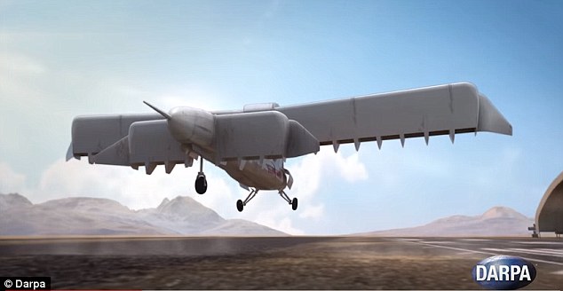
Aurora’s Phase 2 design for VTOL X-Plane envisions an unmanned aircraft with two large rear wings and two smaller front canards—short winglets mounted near the nose of the aircraft. A turboshaft engine—one used in V-22 Osprey tiltrotor aircraft—mounted in the fuselage would provide 3 megawatts (4,000 horsepower) of electrical power, the equivalent of an average commercial wind turbine. The engine would drive 24 ducted fans, nine integrated into each wing and three inside each canard. Both the wings and the canards would rotate to direct fan thrust as needed: rearward for forward flight, downward for hovering and at angles during transition between the two.
The design envisions an aircraft that could fly fast and far, hover when needed and accomplish diverse missions without the need for prepared landing areas. While the technology demonstrator would be unmanned, the technologies that VTOL X-Plane intends to develop could apply equally well to manned aircraft. The program has the goal of performing flight tests in the 2018 timeframe.
Aurora’s unique design is only possible through advances in technology over the past 60 years, in fields such as air vehicle and aeromechanics design and testing, adaptive and reconfigurable control systems, and highly integrated designs. It would also be impossible with the classical mechanical drive systems used in today’s vertical lift aircraft, Bagai said.
The Phase 2 design addresses in innovative ways many longstanding technical obstacles, the biggest of which is that the design characteristics that enable good hovering capabilities are completely different from those that enable fast forward flight. Among the revolutionary design advances to be incorporated in the technology demonstrator:
Electric power generation and distribution systems to enable multiple fans and transmission-agnostic air vehicle designs Modularized, cellular aerodynamic wing design with integrated propulsion to enable the wings to perform efficiently in forward flight, hover and when transitioning between them
Overactuated flight control systems that could change the thrust of each fan to increase maneuverability and efficiency “This VTOL X-plane won’t be in volume production in the next few years but is important for the future capabilities it could enable,” Bagai said. “Imagine electric aircraft that are more quiet, fuel-efficient and adaptable and are capable of runway-independent operations. We want to open up whole new design and mission spaces freed from prior constraints, and enable new VTOL aircraft
This video shows how to use an AirbotPower board to build an Octocopter (a large 1m diameter X8 coaxial config in this example) and what are its functionality.
I made a rover out of my old Axial SCX10. My goal was to use the APM 2.8 for auto missions and maintain the scale look of the truck. At least, as much as possible. Down the road I will make a module for the bed that I can add things like a camera gimbal, FPV, etc.
Here is my APM 2.8, fresh from eBay.
I used some standoffs on the included vibration mount to give clearance for the telemetry radio to mount underneath.
The radio is just double sided taped to the bottom of the APM, it gives about 1mm clearance when mounted.
The completed APM/telemetry unit.
The Axial SCX10 I am using as a base for my build.
What would be a better shot so you can see what I'm working with, if it wasn't so blurry. You get the idea though.
MDF mock up of the electronics plate. Had to move the battery to the rear of the chassis.
Another shot of the mock up showing the overhang.
3D printed electronics plate.
Electronics plate installed with APM module.
Mounting and wiring the receiver to the electronics plate.
Electronics plate with GPS installed.
Ready to test. The GPS mast will be cut down when the body goes on.
I put these 2 6s NiMh 4500mah batteries in parallel for maximum run time, but they don't fit under the bed.
Side view. Installed the RC4WD 1.55 steel beadlock wheels with scale Interco Irok tires.
Fitting the body. It's an Axial made Jeep Mighty FC shell.
Front 3/4 view. There is a separate bumper piece I still need to install.
The APM doesn't quite clear, so I needed to cut a hole in the toolbox and rear window.
Rear 3/4.
Made a 3D printed cover for the hold I cut to clear the APM.
GPS mast cut down to clear the body. You can also see the Novak glitchbuster capacitor I had to add to prevent brownouts under fast acceleration. I imagine if I was running a LiPo this would be a non-issue.
The finished rover. I have plans to design a 3D printed bumper to house some sonar for collision avoidance.
First time out doing an auto mission.
I plan on updating after I finish painting the body, if I ever get a free, rain free weekend.
Until then, enjoy these flex shots.
Here's its first time out doing some all terrain auto missions.
Several year ago, I wrote a booklet entitled Aerodynamics in Plain English. Last week, I convert it to a PDF EBook. I embed the entire book on the front page of my website for viewing (please scroll down to the end of the page). There is also an option to purchase the PDF version if you would like a permanent copy.
The following topics are addressed in Aerodynamics in Plain English:
Basic Concepts
Definition of aerodynamics and fluid dynamics. Find out why aerodynamics is a difficult topic of study.
Forces on an Airplane. Why Does it Fly? Introduction to forces acting on an airplane. Explanation of the role of the lift, drag, weight and thrust forces as related to flight.
What is Density? Definition of density; Comparison of air and water densities; The relations between lift, drag and density.
What is Viscosity? Definition of viscosity; Introduction to the role of viscosity in aerodynamic drag.
What is Compressibility? Definition of compressibility; Speed of sound definition; Mach number definition; Prandtl-Glauert rule.
What is Pressure? Definition of pressure; the relations between lift and drag and pressure; conservation laws and pressure.
Non-Dimensional Numbers Some non-dimensional number in aerodynamics include the lift, drag and moment coefficients in addition to Reynolds number and Mach number.
Reynolds Numbers Definition and importance of Reynolds number. Table with sample calculations of Reynolds number.
Lift, Drag and Moment Coefficients Definition and calculation of lift, drag and moment coefficients. Importance of consistent units examined in calculations.
The Wing Role of different shaped wings; Definition of induced drag; Introduction to tapered, sweptback and delta wings.
How Does a Wing Generate Lift? The relations between conservation of mass, conservation of momentum, streamlines, Bernoulli equation, pressure and lift are discussed in this section.
How Does a Wing Generate Drag? This discussion about the generation of profile drag includes the role of boundary layers, transition points, adverse pressure gradients and laminar flow airfoils.
Airfoils This glossary of terms define the parts of an airfoil and characterize different types of airfoils.
How to Pick Airfoil for Wings
How to use the lift and drag polar plot, the lift and moment versus angle of attack plots to compare airfoils and choose the correct one for your application.
Designing and Testing Airfoils This section introduces inverse design and airfoil modification concepts for designing airfoils. An overview of experimental and computer testing of airfoils is presented.
Considerations for Makers Further consideration for builders examine the role of airfoil thickness in the design of wings.
Definitions A glossary of several terms in the field of aerodynamics.
References Books and software for further exploration of aerodynamics.
The increasing interest in Micro-Air-Vehicles pushed the research and adaption of biology inspired membrane wing structures of bats. Their thin and flexible wing design can improve aerodynamic fight performance at low to medium Reynolds numbers. Membrane wings can combine vehicle agility, enlarged maximum stall angle, extended maximum lift and smooth gust reaction. The main source of their benefits is suggested to rely on their inherent membrane oscillations which can energise the weak boundary layer to enforce longer flow attachment. In addition, membrane vibrations are known to enhance leading edge vortex shedding, forming large roll up vortices of low pressure content which can significantly contribute to the total lift enhancement at high incidences.
The experimental wind tunnel study examines flow structure interactions of membrane wings in high and low altitude. Emphasis is on aspect ratio and the vicinity of the ground. The operation of membrane wings close to a surface could be one further option to gain efficiency and therefore range of MAVs by maintaining the aerodynamic and weight benefits of (passive) membrane wings. A force transducer is used to capture time resolved force measurements whereas Digital Image Correlation (DIC) is selected to resolve membrane motions and Particle Image Velocimetry (PIV) is used to show time resolved modifications in the flow.
Project leader : Robert Bleischwitz
Main supervisor(s): Prof Ganapathisubramani, Dr Roeland De Kat
Autonomous drones have already mastered the wide-open skies. DHL, Amazon, and Google have each demonstrated self-piloting drones that can deliver packages — in fact, the latter two, as The Vergerecently reported, are ready to implement full-scale drone delivery operations in the US and are simply waiting on regulators to get out of the way. But drones that can fly autonomously in complex environments with multiple obstacles (i.e. not the wide-open sky) are another story.
Navigation in terrains that are densely populated with obstacles is an ongoing challenge for researchers. There’s been some headway by a team at MIT, who last November demonstrated an autonomous drone avoiding trees while flying at high speeds in a wide-open field. Now, a group of Swiss researchers have developed technology that allows drones to autonomously navigate forest trails, a development they say could one day aid in search-and-rescue operations.
The group, comprised of researchers from the Dalle Molle Institute for Artificial Intelligence, the University of Zurich, and NCCR Robotics, used deep learning neural networks to tackle the challenge of training an autonomous drone to navigate a densely wooded forest. Teaching a computer to recognize the direction of a trail is a complex task. It can even be difficult for a human to determine the direction of a trail. Just take a look at these photos of trails taken by the researchers and try to determine which direction they’re headed in:
In order to train their algorithm, the researchers mounted three GoPro cameras to a headset and took off on hiking trails across the Swiss Alps. One camera was pointed ahead of the hiker, one to the left, and one to the right. After hours spent on these trails, the researchers had snapped over 20,000 images (images in front of the hiker and on either side). Then they used these images to teach their algorithm what the boundaries of a hiking trail should look like.
The result was a deep-learning algorithm that allows a drone equipped with a single forward-facing color camera to navigate a previously-unseen trail completely on its own — no human interaction whatsoever. The algorithm, the researchers claim, was even better than humans at determining the correct direction of the trails it traveled on, guessing the correct direction of a trail with 85 percent accuracy. Humans tasked with determining the direction of the same trails were able to do so correctly only 82 percent of the time.
The team cautions that these results are still in very preliminary stages. But while there’s a lot more work to be done before autonomous drones will be able to search forests for missing people, the researchers believe their work is a good sign of how deep neural network will allow autonomous vehicles to navigate situations that involve complex and highly dimensional inputs.
Check out the algorithm in action in the video below — which is scored with some pretty rad glitchy video-game music — posted by the researchers.
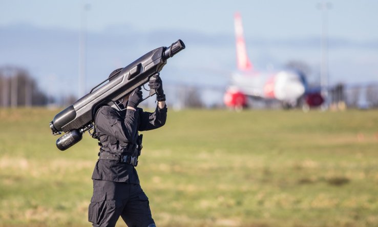
The SkyWall 100 is one of the latest device promising to protect the world from the impending drone takeover. It’s essentially a smart bazooka that fires a canister filled with a net at drones 100 meters away. Boom headshot.
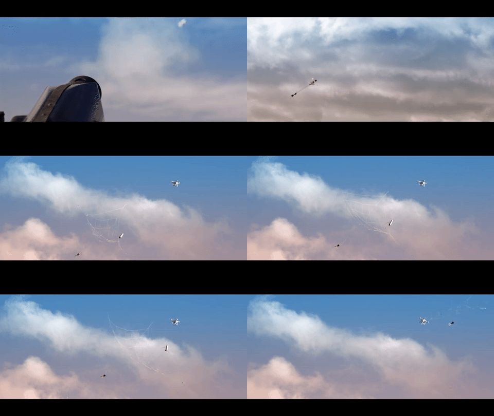
An operator targets the drone and fires a canister that contains a large net that gets tangled in the drone’s rotors. A parachute then delivers the drone back to earth in a civilized manner. OpenWorks Engineering is the company behind the device and is marketing the device to protect sensitive events and buildings. This isn’t something meant to protect your home from snooping neighbors.
The shoulder-mounted device uses an intelligent system that locks onto a drone, assisting the operator in firing and targeting. The scope identifies and then calculates a firing pattern based on the drone’s distance and vector. The technology sounds a lot like the systems inTrackingPoint’s smart guns that lets anyone get a bullseye on a target hundreds of meters away.
The company is also announcing the SkyWall 200, a semi-permanent launcher mounted on a tripod and offers increased range over the SkyWall 100. The SkyWall 300 is a turret-like device designed to be permanently installed. The company says tracking and detection is built into the 300 and operators can control the device remotely.
As drone technology advances, anti-drone technology has followed suited. SkyWall’s solution combine’s brute force with a bleeding edge tracking system. Other devices use radio waves to disrupt the targeted drone’s communications while other systems still use larger drones to capture smaller drones.
SkyWall has not released the price for their systems yet but says it will be available by the end of the year.
At this year's RSA security conference in San Francisco, Dutch security researcher Nils Rodday, currently working for IBM, has revealed a method of hacking high-end drones using cheap custom-built hacking kits that cost around $40 (€36.5).
Rodday conducted his research in this field as a student at the University of Twente in Holland, when a UAV (Unmanned Air Vehicle) manufacturer approached the university to have its products tested.
The UAVs that Rodday got to play with weren't your run-of-the-mill drones, but actual high-end quadcopters sold to police forces, fire departments, and government agencies, for prices ranging from $35,000 to $40,000 (€32,000 to €36,500).
Some over sensationalism and old news, in my opinion, given most telemetry protocols so far have not been designed to be secure in the first place. (e.g. HopeRF radios, Mavlink). So sort of like announcing that some houses with no door locks can be broken into: 1. Locate a door. 2: Push open the door. That said it appears there was at least Wifi WEP at play here, along with Xbees ...
Also a bit difficult to understand how that "police drone" could have been sold for $30,000-$35,000. Looks like run of the mill, Tarot type frame, motors, etc ... X8, $2,000 or so at most?
Eagerly anticipating the great work being done on Mavlink2 at DroneCode!
Here are some photos of my progress on the rotors for my full scale quad. This quad design targets a 200 kg gross wt with 4 rotors of 2.5m diameter. It's mot much progress, but if you're interested here are the pics.
Rotor Tip Weights
Rotor Tip Weight against leading edge (fiberglass) rod.
Layup of leading edge portion of airfoil. Wrapped with 2 layers of 6 oz cloth at 45 deg angle to provide torsional rigidity,
Also, the back end of this section (or this whole assembly) creates a spar which gives rigidity to the blade.
Preparing to glass the tip portion of the leading edge spar section. This will envelope the lead tip weight in glass.
Attaching the rotor tips (shaped wood pieces that rounds the sharp edges to reduce corner stresses on the fiberglass cloth skin.Main foam core placed in position behind the leading edge spar section. Trailing edge is 3/4 x 1/16" aluminum strip with very thin tapered wood strips to give correct taper.
Glassed rotor (tip end). You can see rotor tip cap (wood) and foam core with body filler in areas to smooth the surface.
Flashing of excess fiberglass skin has not been trimmed from trailing edge yet. This glass was wrapped from end to end so as to give strength along the length of the rotor and support the centrifugal loads. Tension in the glass skin is transferred to the inboard tip cap which rests against a composite beam, which in turn is bonded to the FlexElement bearingless hub element.
This is the FlexElement end. Quilted blanket is part of my curing tent setup which allows me to cure the slow-set epoxy at 55C without melting the styrene foam core.
This tutorial demonstrates how to build a Linux drone with the Raspberry Pi Zero using a BOM (Bill of Materials) of less than 200 US$. The drone uses a real-time capable Linux kernel, a Debian-based file system and Dronecode’s APM flight stack compiled for the PXFmini autopilot board. All these components have been put together by Erle Robotics in their OS image for the PXFmini.
This is a picture of an assembly that is part of my full scale (human size) quad-copter rotor blade.
For background, the FlexElement is the structural member that will connect the rotor blade to the rotor hub or head. (shaft). The leading edge rod is an internal structure to give the leading edge of the rotor blade airfoil durability for small impacts. The composite beam is a composite layup which holds it all together, but mainly its function is to transfer the centrifugal forces of the rotor blade (which extends to the left off the page) to the FlexElement.
Originally I did a simple calculation to determine how much surface area I needed for the glue joint between the FlexElement and the composite beam. This was based on the shear strength of the epoxy resin I was using.
A = F / U where U is the maximum stress I want the glue to experience.
In my case F=1600 Lb
U = 5000/4 psi (Lb/in^2) (divide by safety factor of 4:1)
A (minimum) = 1600 / 1250 = 1.28 in^2
My FlexElement rod has an OD of 5/16" or 0.3125", so the circumference is pi * .3125 = 0.982"
So every 1" of bond length along the rod, will give 0.982 in^2 of bond area, so my bond length needs to be at least:
1.28 / 0.982 = 1.30" long. That's how much the rod must insert into the composite beam to provide enough bonding area.
In actual fact, I made the joint length about 4" because of other design factors, so I theoretically had 12 x more area than I needed (safety factor of 4 * (4"/1.3") ~ 12)
I was VERY surprised when this joint failed in simple tension at well below 1600 Lbs of tension.
Lets look why.
My simple bond joint area calculation made one very innocent, but deadly assumption:
That the force or stress would be evenly distributed across the full area of the joint.
WRONG WRONG WRONG WRONG!!
Lets look at a simpler geometry to help understand.
Here is a cut-away of a simple rod glued into a larger cylindrical rod.
The problem with this design is that it produces a concentration of stresses in the glue joint at the point where the rod first enters the cylinder. This is because of the huge, and sudden difference in cross sectional area between the rod, and the rod/cylinder combination at that point.
All materials have elasticity and deform (stretch or compress) when a force is applied to them.
The rod is being pulled in tension, so it is stretched longer than it's normal relaxed length.
Since the glue joint between these two parts is very very thin, we assume that the rod and cylinder dont move relative to each other. But that is not the case here, because the rod is a small diameter, so it is under much greater stress (force per unit cross sectional area) than the green cylinder. So... the rod will be stretching more, so it MUST deform more than the cylinder which is under less stress because the tensile force is spread across a much larger cross sectional area.
When you pull the rod in tension, you quickly cause a stress concentration in the glue joint at the spot indicated.
When the rod pulls to the right, all of that force is concentrated to a small portion of the glue joint. That section of the glue joint fails, and the rod stretches a minute amount. But now, the portion of the glue joint just to the left of the stress concentration area becomes the new stress concentration area, and so on until the joint failure/ stress concentration has moved all the way along the glue joint, and the rod simply pulls out of the cylinder.
This is very hard to describe and visualize because it happens essentially instantaneously, but seeing the results (failure of the joint WAY below what was expected) make it impossible to deny.
THE SOLUTION:
The solution to the problem is to design the two parts (or for simplicity in this case - the cylinder) so that there is a very gradual change in cross sectional area, so that there is a gradual change in the stress, and hence a gradual change in the stretch (strain).
Care must be taken to make this transition gradually so that at no point along the glue joint, does the stress excess the shear strength of the cured glue material.
So back to the stress concentration area, the glue joint only needs to transfer enough force to the "cylinder" (now a cone) to make that tiny, thin green area on the far right to stretch along with the rod which is under full stress.
This force transfer keeps happening along the length of the glue joint until eventually all of the force is tranferred to the green cylinder.
Automated charging systems require a high level of controls performance, especially during the landing process. This is a challenging problem, especially when operating in outdoor conditions, where a gust of wind can easily push the copter off-course.
The video shows a vision-guided precision landing technique, based on the existingAPM:Copterfeature (link). The default code has been reported to produce precision landing performance of ~30cm (i.e., the copter lands 0-to-30cm from the visual target). This is great in general, but the aforementioned automation applications require even better performance. Moreover, in some scenarios, a bad landing results in a crashed copter, for example, when ‘landing on a box’.
The videodemonstratesa modified version of thedefault precisionlandingcode. In the modified version,the copter localizes itself with respect to the visual target, and this localization is used to actively monitor and manage the landing accuracy. In this simple example, the copter is programmed to descend when the landing accuracy is within the specified bounds, and to ascend when outside the specified bounds.The image below shows that the error bound is set to 25cm for the AGL altitude range 1m-to-2m.
This approach can be extended and customized in a variety of ways depending on the particular application. The ultimate goal of ensuring safe and accurate landings for automated UAV systems.
Ground broke last week on developer Trumark Urban's 25-story condo tower, Ten50, at Grand and Eleventh, and at that event developers announced that this high-rise would have the "first-ever" drone landing pad. According to a press release, the drone dock was envisioned for deliveries. Amazon recently received a green light to test drones outdoors and will eventually, inevitably use them some day in the near future to deliver Amazon Prime impulse buys and groceries to homes and offices. Not wanting residents of the building's 151 units to be left behind in some FedEx dark ages, Trumark is going to put a special "landing spot" on the tower's fancy sixth-floor amenity deck.
This project's lucky to be alive, let alone outfitted with ridiculous amenities. The project formerly known as the Glass Tower languished for years, getting jerkedaround until about four years ago, when its lot was listed for sale with entitlements. Within the last 12 months, it's been revived, had its designs tweaked, broken ground, and is looking toward completion in 2016.