All Posts (11086)

Sort by

been a while since I last update on Blog , but happy that this is my first time to Join the Event

it was a 4 day 2 venue event Feb 11-14 both in Clark airport and SM Clark Mall

beside the Highlight of the Hotair Balloon and aerobatics display , Yes RCs and Drones are also a big Part of the event. 

we did have a mini obstacle indoor game in the mall Pitting 3 different Drones , the Professional Photography . DJI Phantom , the Sport FPV drone  & the Toy ARDrone Parrot. 

the the Photos you can See a Swarm of DJI , this explains it all. but after all guess which one Grabs the attention.

if you think the DIY Drone , its correct . DIYs offers a unique style match up to the builders skill and technicality standout among the commercial units. aslong there are tinkerers there will always be room for opensource and a market for parts. 


Read more…

Hi Everyone,

I made a new video describing the details of the Elle0 Paparazzi UAV autopilot. Elle0 is now available for purchase in the 1BitSquared store together with the G0 companion GPS receiver. In the video I go through and describe every IO pin as well as some of the design differences to the Lisa/MX Autopilot that I designed before the Elle0. Additionally, I describe how you can add a battery voltage monitor to your Elle0 using a voltage divider circuit, and how it fits together with the new G0 GPS receiver.

I hope this video is helpful. If you think so too please let me know in the YouTube comments. I am planning to make many more videos describing different aspects of Paparazzi UAV, not only hardware but also flight videos and Paparazzi software tutorials and tips. If you think it will be useful for you make sure to subscribe and tell me in the comments what you would like to see.

Also, check out the Elle0 paparazzi wiki page for more information about the autopilot itself and diagrams of the system. Additionally to the Elle0 and G0 boards we have also released a matching R0 radio board and UU0 UART to USB adapter boards. We will be making videos describing more parts of the modular system we are working on soon. Whereas the Elle0 and G0 are already in stock, the R0 & UU0 are available for Pre-Order in our US store.

Cheers, and successful flights,

Esden and the 1BitSquared team

Read more…

First flight with the Raspberry Pi 3

We managed to get our hands into a Raspberry Pi 3 and decided to give APM a try with it using the PXFmini. Here’s a walkthrough over some of the tests that our team conducted: 

Benchmarking

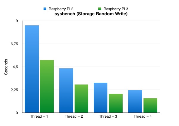
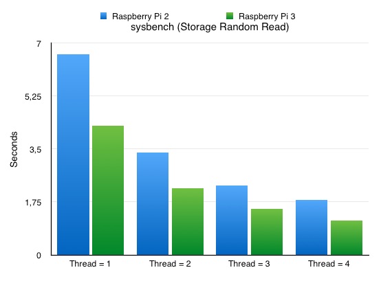
So, down to the benchmarks, we performed 3 types of tests using sysbench and the default Raspbian images (no APM running for now). SysBench is a modular, cross-platform and multi-threaded benchmark tool for evaluating OS parameters that are important for a system running a database under intensive load. The output of sysbench looks like this:

sysbench --test=cpu --cpu-max-prime=20000 run

sysbench 0.4.12:  multi-threaded system evaluation benchmark

Running the test with following options:

Number of threads: 1

Doing CPU performance benchmark

Threads started!

Done.

Maximum prime number checked in CPU test: 20000

Test execution summary:

   total time:                          477.3324s

   total number of events:              10000

   total time taken by event execution: 477.3236

   per-request statistics:

        min:                                 47.69ms

        avg:                                 47.73ms

        max:                                 85.54ms

        approx.  95 percentile:              47.72ms

Threads fairness:

   events (avg/stddev):           10000.0000/0.00

   execution time (avg/stddev):   477.3236/0.00


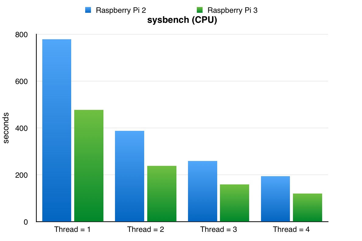
The output is graphed against the Raspberry Raspberry Pi 2 (note that smaller bars indicates better results):

k5cICF47xgcSNlYrz8qWVyb4wQLBoWevCPCHl94me3m5w5EMks4BPQq3LmuA1duff6EWOe7kYkN63JBq1Fh4KFbM-mZqcVIWy2ImaKe4tcyLuL3668adCySkyPTp6eBHy-9JJfAQ

sysbench --test=cpu --num-threads=1 run


HinsJCn2SeFkgFTYC-TDFUR0pVB6Dv1ddZy0dzMpWRq0HLSFqsjmuyCHKODO6IM3_5rSdCzT0j9ThNMsQQ-0uWX2K_Nrl2OVVC10I1Jl8cfzrMYjHSS6WhHSHfcyfxrDweaFmahL

sysbench --test=memory run --memory-total-size=2G

rURY_MBXrYtN-rqabZnH8VUv6iduqjH7r6XHCi4EnCh5nLgu5L-uZm5Y9FnuCXvB_Jgn5hau0pECBAupVCMUYI6NL6VN4ZJuZE8M0YKHybFqtEfKtxbb1rBafPPZjVwcqxh2tSpC

sysbench --test=memory run --memory-total-size=2G --num-threads=1 --memory-oper=read

The 64 bits CPU of the Pi 3 dramatically improves the results of this particular tests over the Pi 2. It’s 40% - 60% faster.

Mounting the autopilot:

We mounted the shield as follows which proved to be robust enough. Vibrations were kept at a reasonable level as will be shown later in the log analysis:

3689682612?profile=original

Flying with APM and log analysis

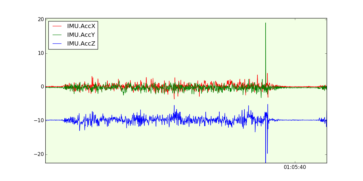
After a short flight we started some checks. The official documentation of APM will tell us:

“Check the scale on the left and ensure that your vibration levels for the AccX and AccY are between -3 and +3.  For AccZ the acceptable range is -15 to -5.“

_Zt0xMUTdjMq0zZ_noEqL7kWMaRVMVZuLzaJQLe2RZV5sxr_0vdr13RBMf4K4knW2obPYuutIn75_I2DjX11-ORtRQHym1MH7a0kvoIT9aw9OLqgU_yceI6rhFtEm8BwW1edOlxf

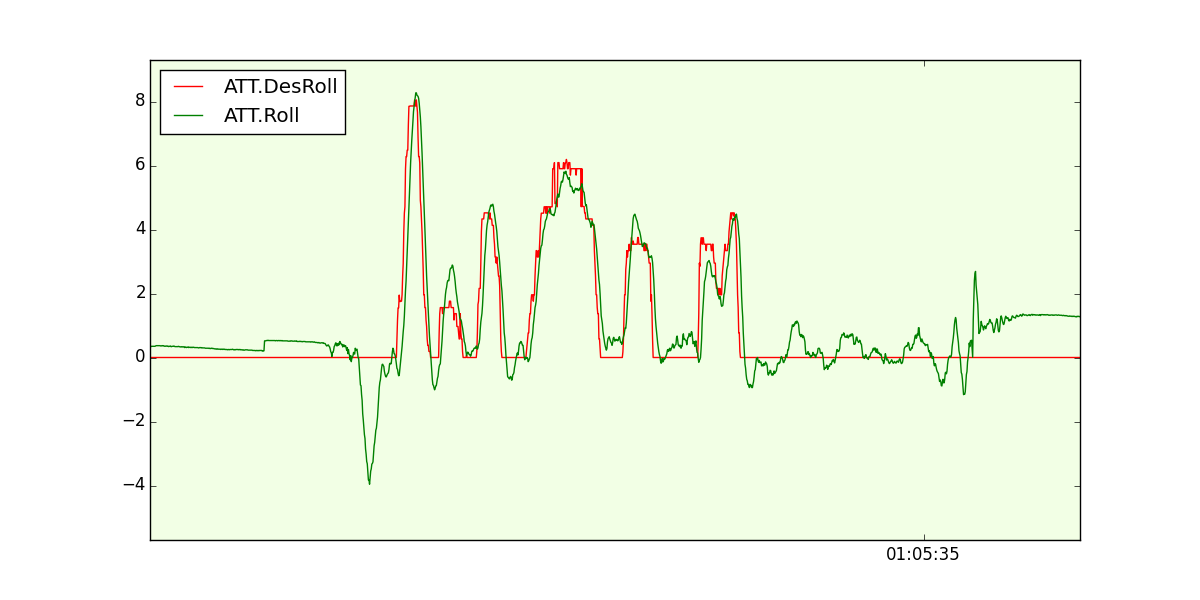
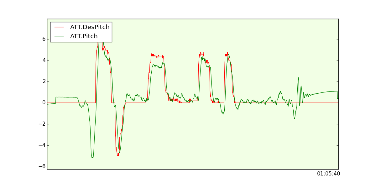
Fine on this. We also felt that the drone was reacting really good so made a few plots that convinced us about the autopilot responses with the Raspberry Pi 3:

dyBj024hPwbAOYdrU9EFfT45nomahOT_rh3JOoEtow-x5foj-DHiYmRX7e5fMX-nobv2G8Dgea64VkjCkwp62HqPtaHSpBRZfCBNPrPbjxAZJSxgVGof3XulLSuhTf-1SJkbTQ1N

 kpzZsCpTKZ3GHyCAZq623y_9CN9wbYO2m6f3d91B6j1It7N0h1NVUMTo_-CTydPPzswm6wj0nq9mkm8ZuZIxcYyI7uaiJJUJeFNWEix371Ef88chwdqomkPI1bt4N0jJPGCFZkTb

Conclusion

Raspberry Pi 3 is a great candidate to make APM Linux autopilots using the PXFmini!. Having Bluetooth and WiFi is indeed a great asset removing the need of using additional USB dongles unfortunately, WiFi is solely b/g/n and does not support the 5 GHz frequency band (which comes handy when flying with RC controllers that work in the 2.4 GHz band).

Read more…

PAPARAZZI UAV ON PIXHAWK TEASER

Hi all Open-Source enthusiast,

Paparazzi UAV, the real Open-Source autopilot driven by a community of users without an economically driven goal. Today we are adding an extra autopilot board to there long list of supported autopilots.

The Pixhawk autopilot board will be integrated in our next software release! The video shows the first flight with Paparazzi UAV on a Pixhawk, more videos will follow.

Why choose Paparazzi UAV?

If you are looking for an advanced, modular open-source autopilot which has features others can only dream of, you choose Paparazzi UAV.

You can make the comparison between Windows and Linux. For example APM is the Windows unfriendly plug and pay software, While Paparazzi UAV is the Linux of autopilot systems, where everything you can imagine is possible.

We make it possible for you to choose the best software for your needs, on the hardware platforms that are right for your project.

Wishing you successful flights,
The Paparazzi dev team

Read more…

DJI are killing it

3689682488?profile=original

http://www.wired.com/2016/03/dji-phantom-4-smarter-faster-super-sleek/

I don't want to like DJI for the same reason I don't want to like Apple - I like open systems that can be tinkered with and that a community can work on together to improve in the long term.  But I'm more and more impressed with what they come up with and how they package it.

With all the recent changes between 3dr and APM, can either or both projects regroup to take them on and provide a compelling price/performance alternative?  The solo is great but was too expensive to compete directly against the phantom 3, perhaps this more expensive phantom might actually be a good thing for the solo?  Has DJI already won the consumer market for good?

Read more…
3D Robotics

3689682571?profile=original

Juan Figueroa wrote to update us on his son's science project using Lidar with drones. Congrats Carlos!

While he had to simplify his project and used an Arduino based obstacle avoiding rover project as a learning phase before trying to use a drone, he earned 1st place in both his school's and district competitions.


He advanced to a regional competition and although he didn't place there, he is still very content with his project. We thought we would pass this picture along... and a sincere thank you for inspiring him. He still cites this conversation as a reason why he chose to pursue this project!

Sincerely

Juan Carlos Figueroa and son
Carlos Figueroa

3689682515?profile=original

Read more…

Sequoia In The Wild!

bGHFbn5EdHTQGYGzUJbjZT-2ZpnFzjqX3MuYM40tw-eAQO-8pKc7A9d_gNSanBtwPAcsl9HBS5fx2l_fnlfxVcz7JuwwODdG-Hdwra2G2K3UnNB98tj_5L7wQ8AxQjrqOFjehSN_TUMAKJ3g1w

Well, not the wild, perhaps the most mapped place on the planet; the Berkeley Marina.

(Disclaimer: I work for Parrot. I did this on my own time, and for my own knowledge and confidence in the product. I was excited by the results, and thought this group would be as well.)

I know many of you here are like me, exploring the capabilities of sUAS vehicles, sensors and processing workflows. It is a quickly changing and dramatic landscape. The business side of drones is equitable to the “Wild West” with dramatic story-lines and pricing shoot-outs happening in the streets. Similarly, the technology side of drones is equitable to the steam engines of the same era. Modern engineers are quickly iterating and surpassing “legacy” technology whose life-span was measured in months, not years.

Enabled by this rapid pace of sensor innovation, Sequoia is a multi-spectral sensor with four discreet-bands, a separate RGB sensor and a fully integrated light incidence sensor including GPS and IMU packaged in a common physical form factor. When Parrot announced the Sequoia sensor at the World Ag Expo a few weeks ago, I still had many questions. “The consumer-product company, Parrot, really made this sensor?” was quickly followed by more useful questions like, “Does it really do what I think it does? What’s the processing workflow? How do I explain this to people?”

As part of my job at Parrot, I have early access to these sensors. While I’m generally a very optimistic person, I’m also a skeptic at heart. I know how difficult it is to engineer, manufacture, test and ship hardware/software products at volume. When a Sequoia came across my desk last week, I couldn’t pass on the opportunity to put it in the air and perform my own, fairly un-scientific, end-to-end validation test. I had very little to do with bringing this product to life, but I am excited by the quality and capabilities. Next time you see a Parrot engineer, give them a high-five.
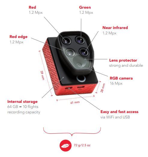
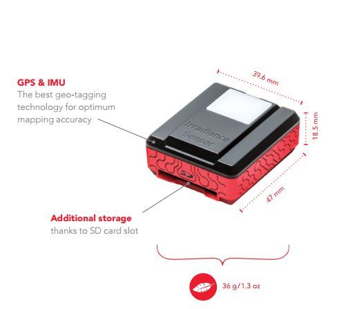
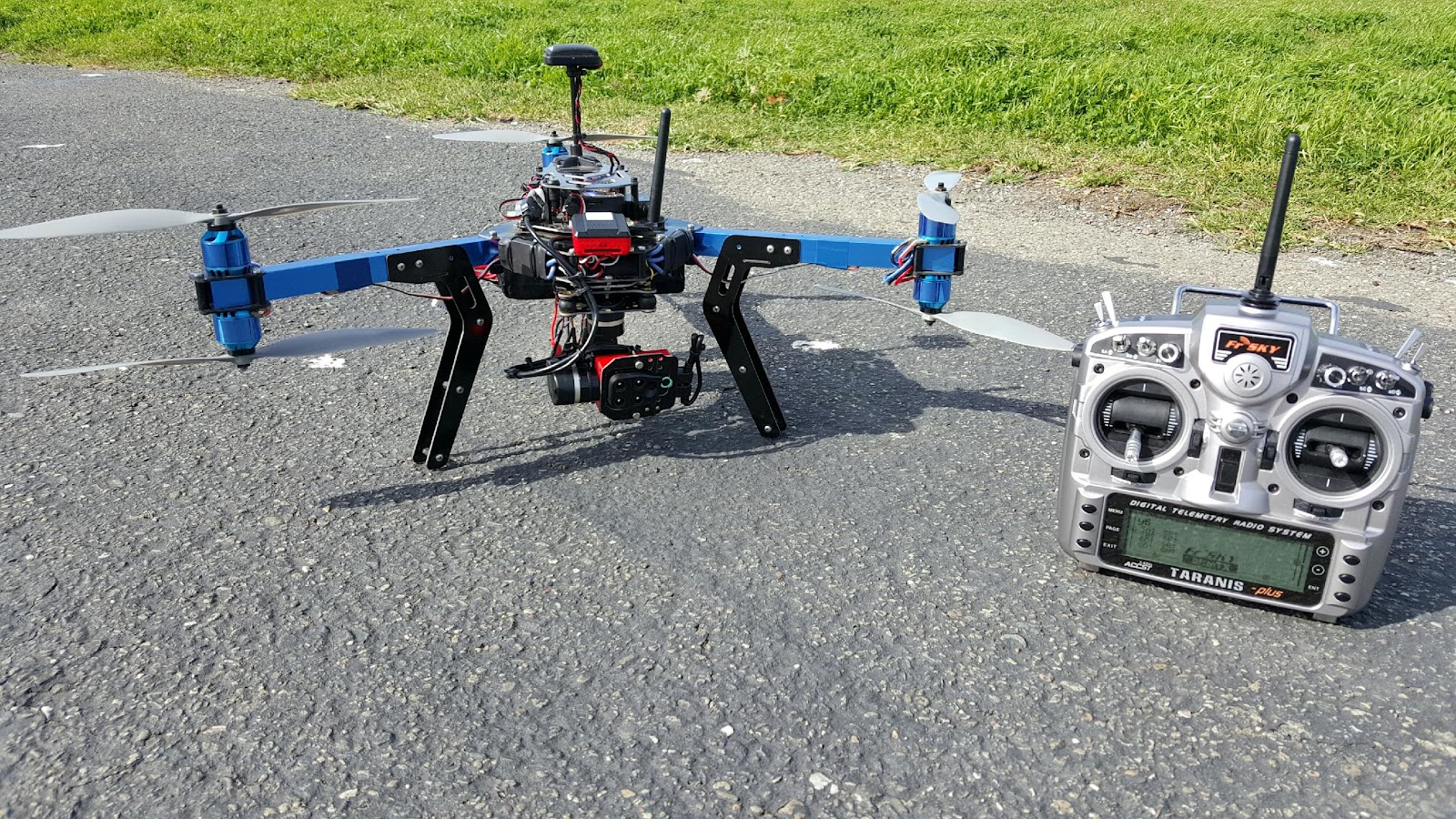
W49AScNJxEj-r9tCRugj_mwgp5GJH4tZXObfcsSYtDR0--CzVQQG143REhpF8nCsiZhyKe8oj52QX73ovqFdEwTk07y2jK9x448EszxtpKqxP4nEIKId4SqeC5J9A9sy_k-Pvq_d7eAkUEVytGu0C-y6b9QKxjg2qvBsFHafulOjcqa9BFqvuEaGtfFZU-B2fUOfYcSO7_9_2aROOUHpkwDH3Ir13H7T7UpuQXJ72kYM1cDQL4OQ5cfy_Dw_Y9MKas0dHnNM6nyiEuhb

Sequoia was designed to be extremely easy to integrate into existing hardware configurations. The only connection the system needs is 5v3A. I added an appropriate BEC to my 3DR Y6, spliced in a female USB connector and the sensor was fully functional. I took a FR4 plate and cut it to fit around the lens array and the camera fit perfectly into the gimbal. The USB cables that the sensor comes with are a little bulky and stiff for this kind of installation, but with some cable routing the package was quickly ready to be put in the air.

Sequoia has an IMU in both the irradiance sensor and the camera itself. What does that mean? The compass dance. Fortunately, it’s painless and very similar to a BeBop2 in duration and complexity. It took about 20 seconds to get through yaw, pitch and roll for both sensors.

There is an SD Card expansion slot in the irradiance sensor. I put a 16GB card in there to make the image transfer super easy. With the amount of data this thing is collecting, it seems that the fastest SD cards you can buy would be a good choice.

In addition to USB PTP control, there is also a WiFi connection available in Sequoia. This allows you to access a browser based camera configuration tool where among many other things you can set time or distance based triggering, or telnet into a root prompt on the camera. Since you can also do this with many other Parrot products, I’m assuming it will also be available on the production version of the sensor. I’m going to keep checking back on http://developer.parrot.com/ to see when they post more information on the API.

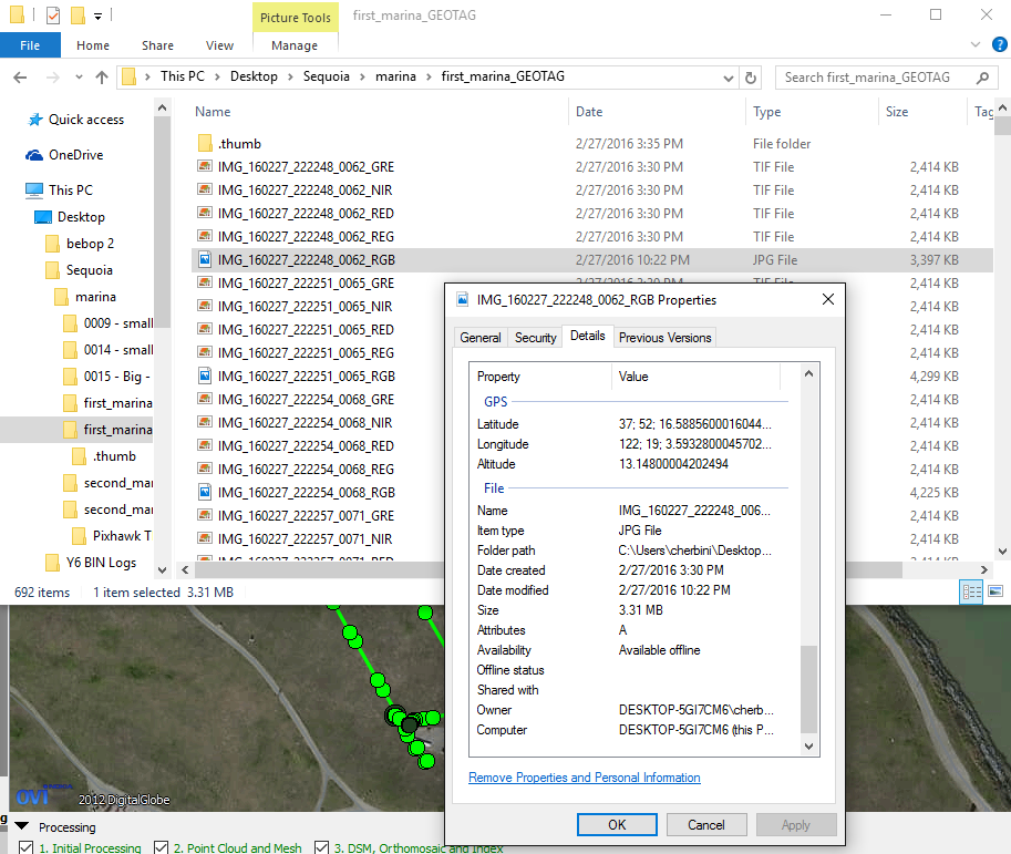
Once powered up in the field, a green light on both the camera and irradiance sensor means that it’s ready to produce fully geo-tagged images. Below is a screenshot of what that means. I did zero configuration to this camera. After initialization, I pressed the shutter button twice to start time based capture at one second intervals (more on this later). As you can see, every time the sensor is triggered, it takes five pictures that are all geo-referenced.
qY1ttdDQnCnkXnhTnZDOAcrJVWf3XsQLOVF2TfvK9WD3vqyANTX0gh2f1dERtKVSHKLCOJ-5HZwLkC2wrsD5RzOnZtuYyO5qFKeLCEtpF4N5hv8bq-tfrpT2mT1wu-MI9lNgndCZ

One of the unique things about this sensor is the discrete bands that it captures simultaneously. The advantage is that the sensor can more precisely measure specific wavelengths than standard RGB sensors. When processing these wavelengths on the back-end, users are able to combine the discrete bands in different indices that best match their specific requirements.
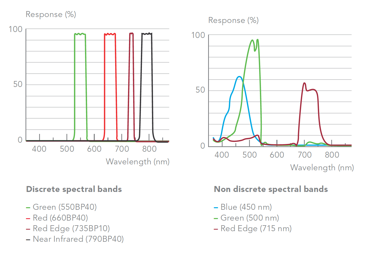
wL9ZmFCvcsAnDxvOusguxRIiifDkAzbUz37Qzbvn7CjM03H9JCzOJhVo_4G360CybUIU9vwBm7HlQ5KSUxL4Gy4kpVL7T8qw-zLIIhj8FbGylxJ6lmgWngI_hFTBZ1DtIMdzTZLEdvbA5nDrhw

After validating that the sensor was working properly on the ground, I started up Mission Planner. I wasn’t sure of Field Of View of the sensor, so I took a guess and used the S110 camera model in the grid planning tool. At 50m planned altitude, this reasonable flight plan is what was generated. After preflight checks and starting the sensor, I sent the Y6 off on its mission.
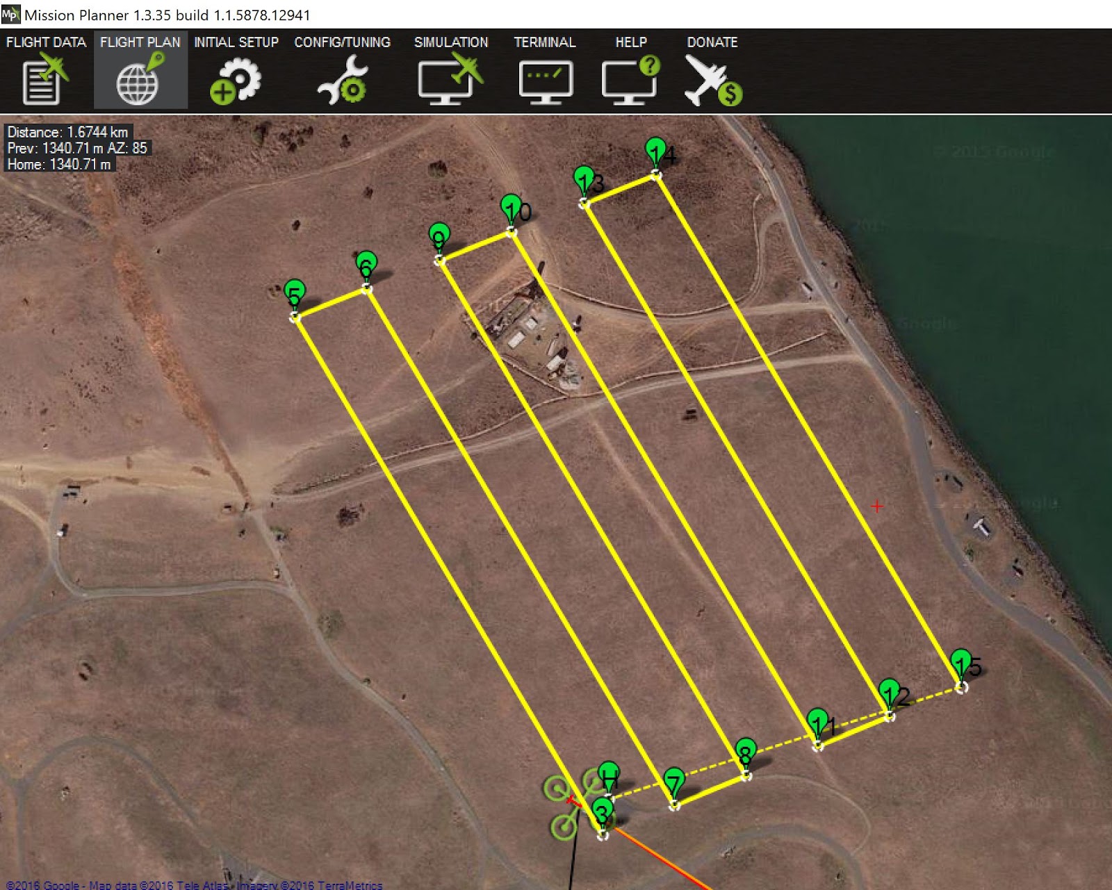
mojUU0o8H-7Y6WtTUv17vXBJeeCjfVn9eGEwhZ7jxv5RViTk2JirzMURapowv-U3JqEZ9M9jVuYa6k0Nv-xFTBbhsNye8y8Gr_U2MlNjBFlH6ET_4tfDHPZxqmEsRRtLdCMBcKBV

The flight went smoothly, and the data was easy to validate in the field. I pulled the SD card from the irradiance sensor, put it in my laptop and made sure there were enough geo-tagged images. I was pleasantly surprised at the quality of the RGB images. Multi-rotors are an inherently bad place to be if you are trying to be precise. I was a little worried about rolling shutter or noise, but those worries were unfounded.

RGB: https://www.dropbox.com/s/pb16jzu5dbltz3y/IMG_160227_224926_0238_RGB.JPG?dl=0

Green: https://www.dropbox.com/s/lxbwa6xm9wz0tsv/IMG_160227_224926_0238_GRE.TIF?dl=0

Red Edge: https://www.dropbox.com/s/nd2rcuyshx924ip/IMG_160227_224926_0238_REG.TIF?dl=0

Red: https://www.dropbox.com/s/tpdcaxc9jxcapjl/IMG_160227_224926_0238_RED.TIF?dl=0

NIR: https://www.dropbox.com/s/17zx8k93srs7ujv/IMG_160227_224926_0238_NIR.TIF?dl=0

Speaking of enough images, a one second interval is clearly too frequent. On this flight, with 5 images taken every second, there are 1791 images for Pix4D to process. 90%+ overlap is unnecessary for this type of processing.
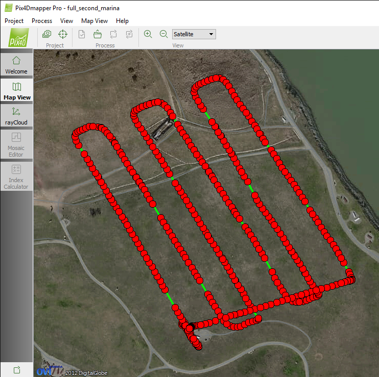
9ig2FwvF-9_res-gJ3a4Gh1Fcnx3kk31NFU9wup8DnhV6rZBDBbExIWqcd4-ezm2oqVvNJudxFCd_DSnSwxCOBghpChnrKBrr9Soe2x1OsKpACiePQLb56wxMn6QgwG35k62c84Y

The next flight will use distance based triggering to test proper overlap, but for now, I manually culled two out of three picture sets to get to a more reasonable 771 pictures. Keep in mind that this is total pictures including all discrete bands and RGB.
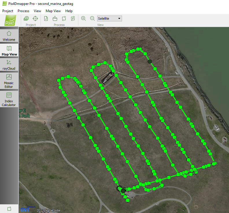
bwmqoG7COIzbIaNKxM-dTafsepF7HTBqrXBzf8ZioMUftg31Kjq451mpcjARRO8VYuXTElqYg6uuDZa8YaJcbE2RkPz9SIsozJLOhYCUPSNg78MYBZATYvQqKosuvcUsc55jbXUp

It’s still not pretty spacing, but we will see what Pix4D thinks of it. Using a beta Pix4D version 2.1.34, the Sequoia images are seamlessly identified and put into an appropriate Camera Rig. https://goo.gl/2Y3Epz
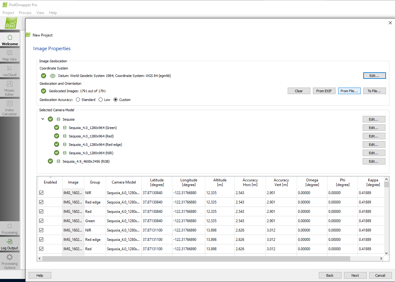
SFHob_01vA9F-rbZwlPGQnCx5cuau3fyloTjx59rnEhTgGi_pRuyXLP05YUJNadLoAohyiGgHuAWVtPTDNGrL8fv6RUvFrSJkWIbYUYWiw6qZhm07IsEPz3psrf9hEoXRSNNpdAo

I am not a Pix4D expert, and I wanted to see how the default configurations worked, so I selected the 3D Maps template and “Start Processing Now!”. Again, I’m more interested in the workflow and time required than fine tuning the knobs available in Pix4D.
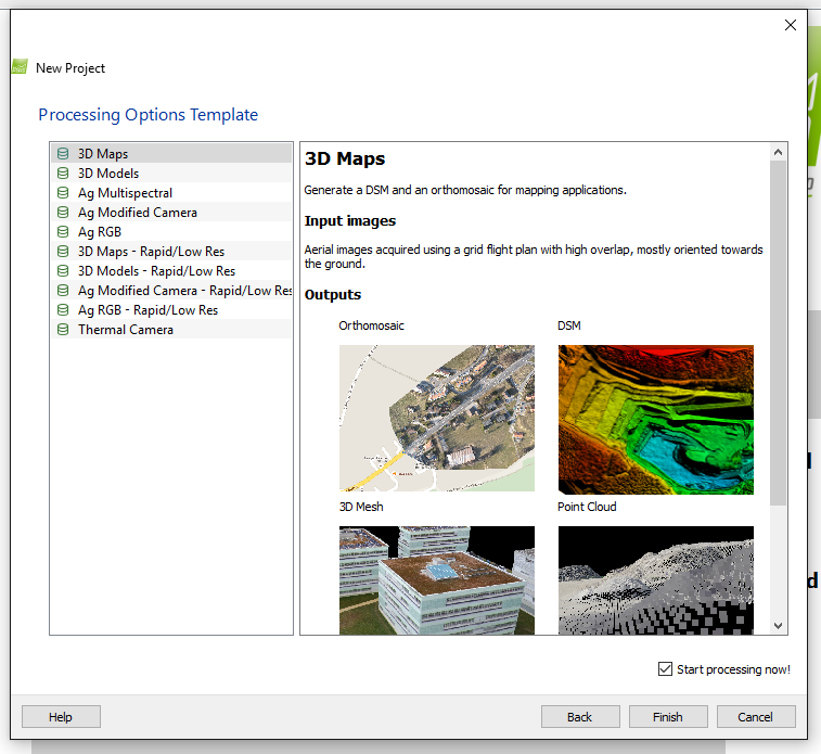
iPkuiYDBDPNrGoeThc8eA312kd_P15Z5cM3p7GM9fXqvC837HXmWRqp6y_gyap49J0nv7IJrlP-fWY9iCS6xxp6RGW_oAtt9LzC_VGu2jFxEm4zGV1tbGB2UhpshUei9kHr19CSW

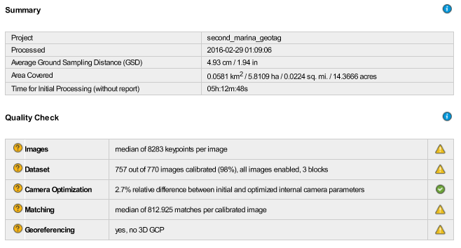
First things first, the quality report. https://db.tt/4kZm0mYA
SGEGHCEsh1ulUHA-wgDw634lkD2U2MjNlUDEmAWom1_IB2MNcvoij7tigh-l_KiCKmkvERcPWTxCjKEq5qGtfENtHezg5Mm9_JlwuFyJWVZeo3l7p9Hrq58ku6v_WvLrt3CnDrfd

Well, not the best looking quality report I’ve ever seen. I assume it’s primarily due to the “shotgun” style triggering and image culling. I like to see the first four checks be green here. The GSD is 5cm at 50M, which seems pretty good to me. Full initial processing took 5 hours, not too bad on a 8GB RAM machine with an Nvidia 970 GPU. I think we should see closer to ten thousand keypoints and I’m not sure why there are three image blocks, I know we want one. It seems to me we’re fairly close on all of these checks though, how did the results come out?
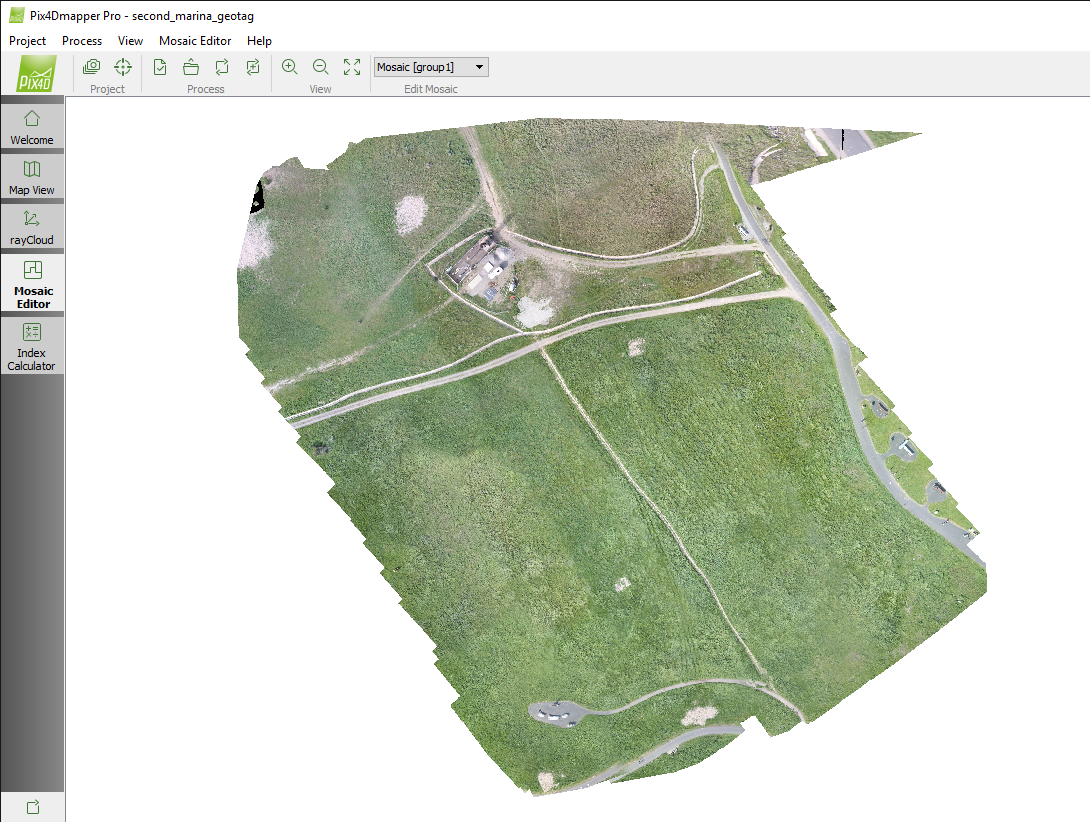
PRsdWLE1UAZeNSbGRNKRWn-UaGZemSdDJEw0JADmvOk76ouqJIVptK5LAtqNgxkdnkq21hqzklPhk5eJjHX9KmN4jpIvg6zw_k4P7PaTuZnaANYJGmsU3Q_M98gV0ziYe1IlIlfe

Coverage area is OK, the top right hand point is not accurate, but sidelap was apparently sufficient. Not a bad result for poor image collection technique and providing nearly zero input into the processing! I’m sure someone who has more experience in Pix4D could clean this up nicely.
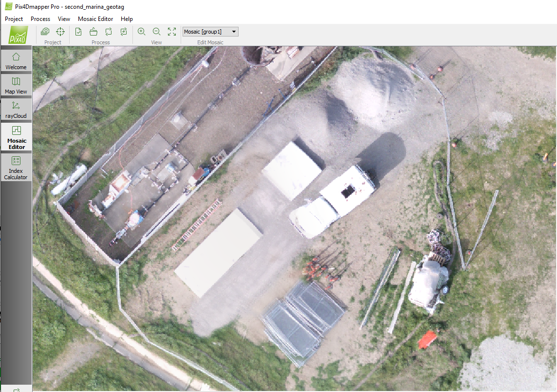
Wfl-pl_nXCn1bPQkfudmZnSWyQP9gKbXSMzY_hE98DMxSweJ8hhOtjBlum6StFZ81tIctRZPe6INpdmEoMtpEKirkA-0jQm79ZWQOOLFfpWjCBlphwIT7hwd-ticH_SBIRGEeRFo

Zoom quality of the ortho also looks pretty good. Nice straight lines, good level of detail, not much ghosting. Here’s a link to the full ortho. https://www.dropbox.com/s/zx1ax2mc30b13fl/second_marina_geotag_transparent_mosaic_group1.tif?dl=0

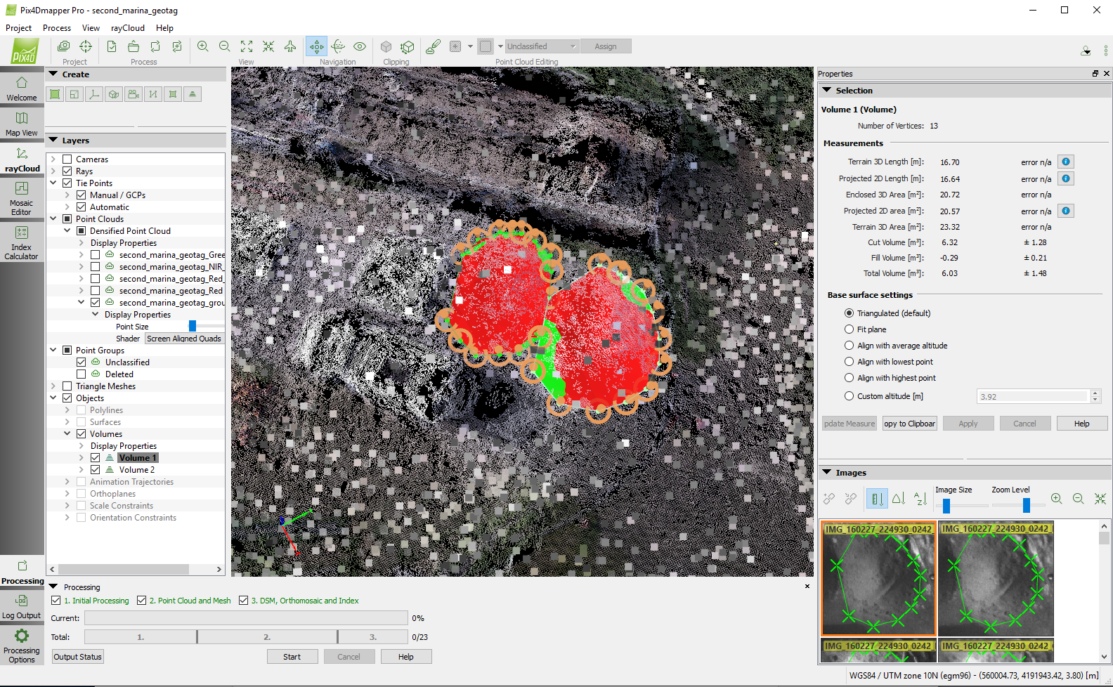
Let’s do a quick sanity check on those aggregate piles.
TQIYzYoloYhJ6w75AKksltTGE-V43DAPJQrbgTUD4W1Uww2RAh_Vs732ZwA0vBkqG76m2vpRlKPd9WCMY5as9JTpfz9kqnElgpeX1eQCHd0l4f4n09cflMqBxm-WE4q-mRYh9vO9

The larger pile is around six cubic meters and the smaller around five. These smaller piles are a little easier to estimate by eye, and by my expert eye measurements, six and five seems pretty close!

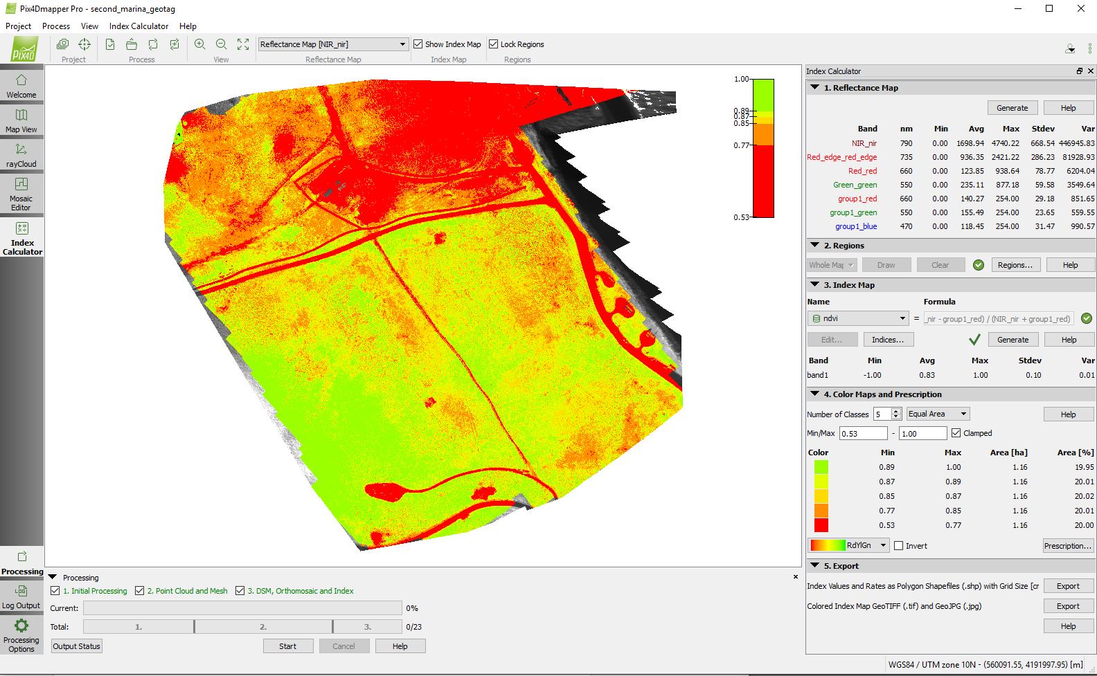
Finally, it’s time to check out what Sequoia was designed to do, produce accurate multi-spectral imagery. Pix4D has done a great job on their Index Calculator, and the changes for Sequoia in this latest beta really help simplify the process of producing vegetative indices.
HcipO3hvQBZFB39nl54dha_QXEqpNkcEbB33QTE2DvVOYc6xVoLtoCa0Hv7US2zf7BHk5HyAgBNc0Da27r7M_c2ABOEt1Rx0Gez7Z0dIIOs0jNm1oLwqG1YfKtsZM98y3fPXc92f

After first generating the reflectance map, you then define the region to analyze, and then the index you want to process. In this case, we have the NDVI index. I think the data in the top right corner (red shading) is questionable, and should ideally be removed from the analysis. The region tool is helpful for excluding information that doesn’t need to be processed. There are many of you here who understand this better than I do, so I will not pretend to be able to interpret this map.

Finally, you can generate and export variable rate prescription shapefiles to import into your precision farming applicator of choice. For example, Ag Leader.

http://www.agleader.com/blog/loading-prescription-files-into-ag-leader-integra-and-versa-displays/
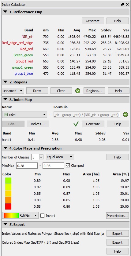
hDr5LK-KromwtaoeK3C5OqTHBXpUellNJNWol1BmMuMBPsO2eVJCe-_CpWDEeq5fIHpYUcuv8XjBiI_PRCUbCRbrCYj9fcg-dZsV34Sfa4tc6Peu6oTRScVrQRVPhzWooA-08eIu

An agronomist or other expert eye is still required to make sense of these vegetative indices in relation to individual crops, but there are companies like Airinov http://airinov.fr working to automate the analysis based on crop specific phenology.

We’ve come a long way in the past few years. While much of this work has been done for decades using satellites and manned aircraft, we are just now able to begin discussing viable end-to-end workflows for drones in the agricultural space.

It is a fact that this multi-spectral and aerial technology are merging in a way that can quickly and accurately produce vast amounts of data for one of the largest industries on the planet. Sequoia takes a great step in commoditizing complex data acquisition for agriculture. Gathering cost-effective, timely, high-resolution data is no longer the challenge it once was.

The challenge we must now overcome is listening to farmer and agronomist requirements on ease-of-use, interoperability and data life-cycle so we as a drone industry provide products and services that can build trust at scale in an industry that is far more experienced, confident in its roots, and wary of newcomers.
Read more…

Emlid Reach for placing GCP

3689682238?profile=originalWe have been using the L1 only Reach GPS from EMLID for about 2 months. We were first attracted to the fact that it claimed that it was going to be integrated to Pixhawk and would then, via a system of magic, give us centimeter accurate geotagged images, eliminating the need for ground control forever.

While we wait for that to become a reality, we have tried out the Reach as a replacement to our normal survey grade Leica GPS1200. We wanted to see just how accurate and robust the Reach is and whether it could be consider a tool for the budget aerial mapper to make more meaningful and accurate models. Despite our office being skeptical of L1 only GPS to give less than decimeter results, we were surprised at the robustness of post processed L1 data.

Our first major project using the Reach was in Zanibar, Tanzania early February 2016. The Reach was used to create a high accuracy GPS tracklog onboard a boat, to be coupled with sonar data, creating a medium accuracy bathymetric survey. Despite the antenna flopping over during the survey, some usable results were obtained. The full story can be read here: 3DroneMapping report

3689682371?profile=original

More recently, we attempted to create a workflow and benchmark test to adopt the Reach as our main surveying tool to place GCP. Having a Leica GPS1200 survey grade GPS has been great for all our projects, but lugging 30kg of additional hardware especially in remote places in Africa, as well the worry of transporting $60 000 worth of gear is a headache. As our workforce continues to grow, it is getting harder to afford such devices for all the teams to use. Placing GCP to a few centimeters is actually a simple process when you remove the RTK element and the Reach seems to do this just fine for us as well as having some other features baked into it for future use like IMU and Pixhawk integration.

The site chosen for the comparison is an active construction site near to Durban, South Africa. Points were surveyed by our office 3 months ago via a Leica GPS1200. The points have been semi permanently marked with road marking paint on tar, plastic bags arranged in "X" formation and other ways, making all points visible from the air for photogrammetric uses. The points were initially measured in RTK and then confirmed with a local NTRIP VRS server. The survey is based on the VRS coordinate system, Hartebeesthoek94 / Lo31 (EPSG:2054).

We wanted to test the Reach in 2 ways. The first being via RTK ways and then by post processing. A total of 3 Reach devices were used. It was decided to not use the Reach with an attached RFD900 radio. Previous tests have shown that the radio range, even at maximum power output, is not really useful for terrestrial work. We suspect that the polarization of the antennas is best suited for ground to air communications. It as then decided to send RTCM data via a TCP server, connected to an ADSL line(via a WIFI router)

3689682463?profile=original

The first Reach was installed at our office, 3km away from the site. This Reach, "BASE1" was to act as a reference base. The Reach was connected to the office WIFI and assigned a static IP. The antenna was installed on the roof of the office with a 300mm x300mm metal plate acting as a ground plane. The Reach was connected to our VRS and a coordinate was determined within 20 seconds. The point was averaged for over 30 seconds. This point occupation would form the basis of our control system making it easier to compare to the true system.

"BASE1" now had a coordinate, and was set to "Base" mode. The coordinate entered in the respective fields, the output set to "TCPServer", GPS and GLONASS data was sent at 1HZ. Before leaving the office, we tested that the data stream was accessible from outside of our local network via the Android app "Lefebure NTRIP Client"

On the site, "BASE2" was installed. This consisted of an antenna being installed on a 300mm x300mm metal plate acting as a ground plane, in an open area, elevated on a wooden fence post. The Reach was connected to a portable WIFI router, in turn connected to a public 3G service. The portable WIFI router was used as an access point to use Reachview as well as the internet. A Androind cellphone was also connected to the mobile WIFI network and Reachview accessed via Chrome browser. "BASE2" was initialized with the default Reach settings and configured to use "BASE1" via TCP client. After a 15 seconds, a solution was derived and stored. Reach was then placed in the default "Single" mode with GPS/GLONASS satellites being used at 1hz. The data being stored onboard.

Various points were then surveyed about the site. The 3rd Reach was setup on a 2m pole. The antenna placed on a 200mmx200mm sheet metal plate, and a plumbing bubble installed on the pole to ensure it was held vertically over every point. The point was located and then the pole/antenna positioned over the previously surveyed mark. The Reach was placed in the default RTK mode but "Static" was the operation of choice as the antenna would not be moving during the observation window. RTCM data was being received from "BASE1", all raw observations were being stored as well as the solution. The measurement windows lasted for 60 seconds per point, at 1hz. Most points had open clear view of the sky about them, but 2 locations had high tension power lines overhead, which made for some interesting results. The starting points were measured at the end of the survey again to ensure that the base had not moved and to test the integrity of the data.

After each point was measured, the base was retrieved and the data downloaded. Rinex files were determined for "BASE2" and for each of the measurements. The solutions calculated in the field were collected and tabulated ofr each point. The TCP measured data collected from BASE1 was also tested via RTKLIB v2.4.3 b8. The exact same result was created on a PC via post processing from BASE1 to what was determined in the field.

Post processing from BASE2 yielded much better results. These were tabulated and compared to the original values from the Leica GPS. The configuration used to calculate the positions was the default RTKLIB settings, using Static modes and a single solution derived.

3689682425?profile=original

3689682387?profile=original

In the table, the X,Y,Z,dX,dY,dZ columns are in meters, the coordinate system being Hartebeesthoek94 / Lo31 (EPSG:2054). These were calculated from the raw processed WGS84 coordinates in ArcGIS and the South Africa geoid model applied to obtain orthometric heights. The "Original" columns are the the Leica GPS1200 surveyed and adopted results as true sub 30mm accuracy.

As can be seen, there are a lot of inconsistencies with the TCP data stream corrected solutions from "BASE1". However, when compared to the PP solutions of "BASE2", the results really do appear favorable and perfectly suitable for placement of GCP.

This is a really accurate result from such affordable and simple hardware. Using proper survey techniques and understanding what is going on with processed GPS data helps a lot in getting the best from these devices.

We conclude that:
- Post processing is really robust and works well to getting good results, especially regarding heighting

- There are a few latency issues with using a TCP server. We think that in our case, having the data being streamed at 5hz from BASE1 > Router > ADSL > Internet > 3G > Mobile WIFI > Reach is a bit long winded causing data delays / loss.

- 1hz is perfectly fine for static observations. For post processing, good measurements come from long observation windows and not the amount of raw data used to process with.

- Having a good ground plane helps a lot to reduce multipath as well as having obstruction free view of the sky.

- L1 only is not that robust and the control point areas need to be carefully considered to reduce multipath and long baselines

- It would be really great if coming versions of Reach could also allow for raw observations to be recorded while in "Base" mode. These could be used as a back up if the communication goes down between units as well as offering a more more robust solution possibility.

- The RTKLIB method is a bit painful when it comes to multiple points as there is no way of assigning a name to an observation. One needs to alternatively log the time and name / details for compiling a coordinate list. Each point needs to be individually processed, taking time.

- A set of Emlid Reach GPS units (at less than $600 for a pair!) is perfectly fine to place sub 50mm accuracy control points for UAV photogrammetry.

Device Setup is as follows:
BASE1
Reach running Reach image V1.1, Reachview V0.1.0
Powered via 5v DF13 at 2ah
Tallysman TW-4721 placed on 300mmx300mm sheet metal, unobstructed
Conected via WIFI/4mbps internet ADSL connection
Static IP TCP Server
Broadcasting RTCM data at 5hz

BASE2
Reach running Reach image V1.2, Reachview V0.1.0
Powered via 5v USB at 2ah
Tallysman TW-2410 placed on 300mmx300mm sheet metal, unobstructed
No internet / WIFI connection
Recording raw data at 1hz

Rover
Reach running Reach image V1.2, Reachview V0.1.0
Powered via 5v USB at 2ah
Tallysman TW-4421 placed on 200mmx200mm sheet metal on 2m plumbing pole
Mobile WIFI connection via 3G for Reachview / TCP client
Recording raw data at 1hz

Read more…

It's a solution that you can build and upload the last APM 3.2.1 code for MEGAPIRATE BOARDS and AVR atmega2560 GENERICS BOARD with I2C bus communication.

As you know, megapirate team stop building APM and the last code was 3.1.5 version, we are desired work and port the last AVR APM 3.2.1 to this board, megapirate and AVR boards with atmega 2560 and I2C bus communication.

TESTED AND WORKING on MEGAPIRATE BOARDS:

   - ArduCopter 3.2.1
   - AntennaTracker 0.7.2

VIDEO WORKING APM 3.2.1 ON MEGAPIRATE:


    https://www.youtube.com/watch?v=baIYXkhdYcU

1. SOFTWARE TOOLS REQUIRED
--------------------------

These tools you need to download first.

1.1 Arduino 1.0.3 with gcc-4.8.2 version download from this link:

http://firmware.diydrones.com/Tools/Arduino/ArduPilot-Arduino-1.0.3-gcc-4.8.2-windows.zip

1.2 Git tool, download from this link:

https://git-scm.com/downloads


2. STEPS FOR COMPILING
----------------------

2.1 Download and Decompress Arduino from section 1.1 to c:\arduino. You will see this order path c:\arduino\hardware\tools\avr\bin

2.2 Download and install GIT tool from section 1.2 to default path. NOTE.- in the steps windows install choose the option:

"Run Git from the Windows command Prompt"

2.3 Open Explorer and navigate to 'c:\' drive, right click and select "Git bash here", it's open a windows command prompt.

2.4 In prompt command line type the next command to clone ArduCopter-3.2.1_I2C branch as follow:

$ git clone https://github.com/hiro2233/URUS8.git ardupilot
$ cd ardupilot
$ git checkout ArduCopter-3.2.1_I2C

2.5 Open Arduino, go to File, Preferences, in "sketchbook location" click on Browse and choose the path where are the ardupilot folder you checkout with GIT,
in this case c:\ardupilot, ok and close.

2.6 Now load Arducopter sketch, compile and upload to the MEGAPIRATE board.

Enjoy!

BUILDING CODE FOR ANTENNA TRACKER

-------------------------------

1. SOFTWARE TOOLS REQUIRED
--------------------------

These tools you need to download first.

1.1 Arduino 1.6.6 version, download from this link:

http://arduino.cc/download.php?f=/arduino-1.6.6-windows.exe

1.2 Git tool, download from this link:

https://git-scm.com/downloads

1.3 fix_includes_arduino166 program, With this tool you can change all include headers files to work with arduino 1.6.6 in windows.
You need compile the code, it's included on repo branch master-AVR Tools/ArdupilotMega_ON_Generic_Board/


1.4 Notepad++, download from this link:

https://notepad-plus-plus.org/download/v6.8.8.html


2. STEPS FOR COMPILING
----------------------

2.1 Download and Install Arduino from section 1.1 to default path.

2.2 Download and install GIT tool from section 1.2 to default path. NOTE.- in the steps windows install choose the option:

"Run Git from the Windows command Prompt"

2.3 Download and install Notepad++ from section 1.4 to default path.


2.4 Open Explorer and navigate to 'c:\' drive, right click and select "Git bash here", it's open a windows command prompt.


2.5 In prompt command line type the next command to clone Ardupilot master-AVR branch as follow:

$ git clone https://github.com/diydrones/ardupilot.git
$ git checkout master-AVR
$ echo "ARDUINO=/c/arduino" > /c/ardupilot/config.mk


2.6 Compile Tools\ArdupilotMega_ON_Generic_Board\fix_includes_arduino166 with VS2013 or SharpDevelop (with this one was compiled).
Then you use as follow:

fix_includes_arduino166 -P <PATH_TO_FOLDER>

Example: Supose that you cloned Ardupilot in c:\ardupilot then you will have c:\ardupilot\libraries and you want make AntennaTracker c:\ardupilot\AntennaTracker then,

fix_includes_arduino166 -P c:\ardupilot\libraries
fix_includes_arduino166 -P c:\ardupilot\AntennaTracker

WARNING!
This tool make changes to the files in all librarie path and this tool doesn't make a backup of your files. You must be sure.

2.7 Open Arduino, go to File, Preferences, in "sketchbook location" click on Browse and choose the path where are the ardupilot folder you checkout with GIT,
in this case c:\ardupilot

2.8 Open the next file with notepad++, c:\ardupilot\libraries\AP_HAL\AP_HAL_Boards.h and replace this line #define AVR_ARDUINO_ENVIRONMENTS with //#define AVR_ARDUINO_ENVIRONMENTS. Save and close.
NOTE: If you uncomment this line, you are telling to Arduino make code for AVR Generic Board, but if you comment with this line with '//' you are telling to Arduino make code for APM2 Board.

2.9 Open AntennTracker in Arduino and compile.

ENJOY!

If you are looking for detailed and description file libraries modification follow the oficial PR on the oficial Ardupilot repo at:


    https://github.com/diydrones/ardupilot/pull/3578  ;

(DEVELOPERS) AVR and MEGAPIRATE DEVELOPMENT SUPPORTS Version Boards
Chat discussions at https://gitter.im/dronebo/URUS8


(USERS) MEGAPIRATE and AVR SUPPORT
Forum Discussions and supports at http://drone.bo/foro/development-english/apm

Read more…
3689682301?profile=originalA report released last Friday by the Australian Government’s Commonwealth Scientific and Industrial Research Organisation (CSIRO) contains some pretty interesting reading, particularly for those of us involved in the RC community.

The report, ‘Tomorrows Digitally Enabled Workforce’, looks at changes to the workforce and society being driven by technology. These changes are likely to bring with them significant disruptions to segments of the workforce, and reports such as this are being used by government to help understand future workforce needs and manage the career transitions that many will be forced to make.

One of the encouraging messages that I took from the report, was that many more jobs are likely to be created through technological change than destroyed. Based on a combination of short term forecasting of current job requirements and longer term forecasting based on trends and scenarios, the report speculates about six new ‘jobs of the future’. One of these six new job types is remote controlled vehicle operators.

The rise in un-crewed vehicles is giving rise to a new workforce of pilots, drivers and ship captains along with those with the skills to maintain the hardware and develop the software - not to mention those involved in training this new workforce. The Australian Civil Aviation Safety Authority (CASA) has already noted more than 650 applications for remotely piloted aircraft alone, categorising the applications as 'mostly dull, dirty, dangerous and demanding and best done remotely given the risk to human safety'. The report predicts continual growth in the number and diversity of jobs for RC vehicle operators over the next 20 years, as automation plays a greater role in improving safety and efficiency.

With autopilot developers, aerial camera operators, communications engineers and RC retailers making up the regular weekend crowd at the field where I fly, the shift is already apparent to me (the programmers just need to make sure they don’t inadvertently manage to program themselves out of a job).

If nothing else, the report gives me licence to further indulge my nine year old's passion for RC aircraft on the basis that it could be much more than just weekend fun.
Read more…
3D Robotics

3689682328?profile=original

Good news from Blue Robotics: they've crossed the final(?) frontier and ArduPilot is now underwater. Welcome ArduSub! (In historic progression since the founding of the project it was Plane, Copter, Rover, Boat and now Sub) 

All details are here, but this is the summary:

Firmware for Remote-Operated and Autonomous Capabilities in Underwater Vehicles

The ArduSub project is a fully-featured, open-source controller for remotely operated underwater vehicles (ROVs) and autonomous underwater vehicles (AUVs). Based on the popular ArduCopter code, the ArduSub code has extensive capabilities out of the box including feedback stability control, depth and heading hold, and autonomous position control if provided with position feedback.

ArduSub is designed to be safe, feature-rich, open-ended, and easy to use even for novice users.

System Components

  • A PixHawk or other DroneCode-compatible autopilot loaded with the latest version of the ArduSub firmware.
  • QGroundControl software for setup, configuration, and operation of the vehicle.
  • A suitable ROV or AUV for use with the software
  • Many other useful additions: depth sensors, tether communications, cameras, and other sensors and actuators

ROV/AUV Types

ROVs

  • ArduSub currently supports two frame configurations:
    • BlueROV 6DOF Frame: Maneuvers with unique 6 degree-of-freedom control
    • Vectored w/ Side-by-Side Vertical Thrusters: Provides excellent smooth control and stability
    • Vectored w/ Corner Vertical Thrusters: Provides excellent smooth control, stability, and 6-DOF control
  • In the future, other frame types will be supported, such as:
    • 3 and 4 thrusters arranged with two thrusters for forward/turn and one or two for vertical
Read more…

At DIAGO 2016

Each year, the Association of Technical Diagnostics of the Czech Republic organizes the DIAGO2016 conference, which took place this year in the spa town of Luhačovice in the HARMONIE I hotel.

3689682277?profile=original

We participated in the conference, as we do each year, and presented FLIR thermal cameras and our latest thermal imaging system for drones, which were give the final name of Workswell WIRIS. 

3689682208?profile=original

Our presentation included, in addition the traditional exhibition in the form of an exhibition kiosk, flying with drones for the conference participants. Our partner at the conference was the Vertical Images company, who presented two drones, the largest of which had installed our older Workswell Thermal Vision Pro (with white cover) thermal imaging system.

Read more…

New Raspberry Pi 3 is about to be announced, it will bring 64-bit 1.2Ghz cores and Wi-Fi connectivity. It is surely an exciting update for Navio2 and we can’t wait to get it into the air.


3689682252?profile=original


It is expected that the new processor will be similar to the previous BCM2835 with upgraded cores (probably Cortex A53), just like it was with the previous upgrade from single-core ARMv6 to quad-core ARMv7. That means that the peripheral blocks should stay the same and will have a high level of compatibility while bringing more performance. Cortex A53 is 30-40% faster than Cortex A7 according to data from ARM.


Build-in WiFi and BLE should simplify the configuration of the board eliminating the need in USB adapters.

As soon as we get our hands on the board we will make sure that it is supported by APM and will work with Navio2 autopilot HATs. As Raspberry Pi foundation maintains 40-pin connector compatibility it should be a seamless upgrade. We are yet to see how different the software will be for the new processor.

v8x7H86b83-TmcPwNUwJ9JuWOVD-PxaXopv7UIDUys7oNnR3fEVCzn67fcKkVrUJT-0W7--qlpMhKsNmnVc-phFEE24FWamQZdahVmB5oRIUrVeds8M7LLC2h7xnUdH2qfrw8ZGT?width=624


Thanks to CNX-Software for bringing the news. You can read more about Navio2 autopilot at emlid.com .


Read more…
Developer

A new chapter in ArduPilot development

3689682203?profile=original

The ArduPilot core development team is starting on a new phase in the project's development. We’ve been having a lot of discussions lately about how to become better organised and better meet the needs of both our great user community and the increasing number of organisations using ArduPilot professionally. The dev team is passionate about making the best autopilot software we can and we are putting the structures in place to make that happen.

Those of you who have been following the developments over the years know that ArduPilot has enjoyed a very close relationship with 3DRobotics for a long time, including a lot of direct funding of ArduPilot developers by 3DR. As 3DR changes its focus that relationship has changed, and the relationship now is not one of financial support for developers but instead 3DR will be one of many companies contributing to open source development both in ArduPilot and the wider DroneCode community. The reduction in direct funding by 3DR is not really too surprising as the level of financial support in the past was quite unusual by open source project standards.

Meanwhile the number of other individuals and companies directly supporting ArduPilot development has been increasing a lot recently, with over 130 separate people contributing to the code in the last year alone, and the range of companies making autopilot hardware and airframes aimed at ArduPilot users has also grown enormously.

We’re really delighted with how the developer community is working together, and we’re very confident that ArduPilot has a very bright future

Creation of ArduPilot non-profit

The ArduPilot dev team is creating a non-profit entity to act as a focal point for ArduPilot development. It will take a while to get this setup, but the aim is to have a governance body that aims to guide the direction the project takes and ensure the project meets the needs of the very diverse user community. Once the organisation is in place we will make another announcement, but you can expect it to be modelled on the many successful open source non-profits that exist across the free software community.

The non-profit organisation will oversee the management of the documentation, the auto-build and test servers and will help set priorities for future development.

We’re working with 3DR now to organise the transfer of the ardupilot.com domain to the development team leads, and will transfer it to the non-profit once that is established. The dev team has always led the administration of that site, so this is mostly a formality, but we are also planning on a re-work of the documentation to create an improved experience for the community and to make it easier to maintain.

Expansion of ArduPilot consulting businesses

In addition to the non-profit, we think there is a need for more consulting services around ArduPilot and DroneCode. We’ve recognised this need for a while as the developers have often received requests for commercial support and consulting services. That is why we created this commercial support list on the website last year:

http://planner.ardupilot.com/wiki/common-commercial-support/

It is time to take that to the next level by promoting a wider range of consulting services for ArduPilot. As part of that a group of the ArduPilot developers are in the process of creating a company that will provide a broad range of consulting services around ArduPilot. You will see some more announcements about this soon and we think this will really help ArduPIlot expand into places that are hard to get to now. We are delighted at this development, and hope these  companies listed on the website will provide a vibrant commercial support ecosystem for the benefit of the entire ArduPilot community.

Best of both worlds

We think that having a non-profit to steer the project while having consulting businesses to support those who need commercial support provides the best of both worlds. The non-profit ArduPilot project and the consulting businesses will be separate entities, but the close personal and professional relationships that have built up in the family of ArduPilot developers will help both to support each other.

Note that ArduPilot is committed to open source and free software principles, and there will be no reduction in features or attempt to limit the open source project. ArduPilot is free and always will be. We care just as much about the hobbyist users as we do about supporting commercial use. We just want to make a great autopilot while providing good service to all users, whether commercial or hobbyist.

Thank you!

We’d also like to say a huge thank you to all the ArduPilot users and developers that have allowed ArduPilot to develop so much in recent years. We’ve come a very long way and we’re really proud of what we have built.

Finally we’d also like to thank all the hardware makers that support ArduPilot. The huge range of hardware available to our users from so many companies is fantastic, and we want to make it easier for our users to find the right hardware for their needs. We will continue working to improve the documentation to make that easier.

Happy flying!

The ArduPilot Dev Team

Read more…
Developer

Autopilot needs survey

dc_slide_intro.jpg?itok=_zX5VTF5

We have put together a survey to capture information about what professional users are looking for in an autopilot.
Please fill out this survey for all of the vehicle types you would like to fit an autopilot into.
Thank you
cleardot.gif
Read more…
Developer

Building, flying and crashing a large QuadPlane

IMG_20160219_155205.jpg?width=600

Not all of the adventures that CanberraUAV have with experimental aircraft go as well as we might hope. This is the story of our recent build of a large QuadPlane and how the flight ended in a crash.

As part of our efforts in developing aircraft for the Outback Challenge 2016 competition CanberraUAV has been building both large helicopters and large QuadPlanes. The competition calls for a fast, long range VTOL aircraft, and those two airframe types are the obvious contenders.

This particular QuadPlane was the first that we've built that is of the size and endurance that we thought it would easily handle the OBC mission. We based it on the aircraft we used to win the OBC'2014 competition, a 2.7m wingspan VQ Porter with a 35cc DLE35 petrol engine. This is the type of aircraft you commonly see at RC flying clubs for people who want to fly larger scale civilian aircraft. It flies well and the fuselage and is easy to work on with plenty of room for additional payloads.

VQ Porter QuadPlane Build

The base airframe has a typical takeoff weight of a bit over 7kg. In the configuration we used in the 2014 competition it weighed over 11kg as we had a lot of extra equipment onboard like long range radios, the bottle drop system and onboard computers, plus lots of fuel. When rebuilt as a QuadPlane it weighed around 15kg, which is really stretching the base airframe to close to its limits.

To convert the porter to a QuadPlane we started by glueing 300x100 1mm thick carbon fibre sheets to the under-surface of the wings, and added 800x20x20 square section carbon fibre tubes as motor arms. This basic design was inspired by what Sander did for his QuadRanger build.

IMG_20160212_143527.jpg?width=600in the above image you can see the CF sheet and the CF tubes being glued to the wing. We used silicon sealant between the sheet and the wing, and epoxy for gluing the two 800mm tubes together and attaching them to the wing. This worked really well and we will be using it again.

For the batteries of the quad part of the plane we initially thought we'd put them in the fuselage as that is the easiest way to do the build, but after some further thought we ended up putting them out on the wings:

IMG_20160218_200021.jpg?width=600They are held on using velcro and cup-hooks epoxied to the CF sheet and spars, with rubber bands for securing them. That works really well and we will also be using it again.

The reason for the change to wing mounted batteries is twofold. The first is concerns of induction on the long wires needed in such a big plane leading to the ESCs being damaged (see for example http://www.rcgroups.com/forums/showthread.php?t=952523&highlight=engin+wire). The second is that we think the weight being out on the wings will reduce the stress on the wing root when doing turns in fixed wing mode.

We used 4S 5Ah 65C batteries in a 2S 2P arrangement, giving us 10Ah of 8S in total to the ESCs. We didn't cross-couple the batteries between left and right side, although we may do so in future builds.

For quad motors we used NTM Prop Drive 50-60 motors at 380kV. That is overkill really, but we wanted this plane to stay steady while hovering 25 knot winds, and for that you need a pretty high power to weight ratio to overcome the wind on the big wings. It certainly worked, flying this 15kg QuadPlane did not feel cumbersome at all. The plane responded very quickly to the sticks despite its size.

We wired it with 10AWG wire, which helped keep the voltage drop down, and tried to keep the battery cables short. Soldering lots of 10AWG connectors is a pain, but worth it. We mostly used 4mm bullets, with some HXT-4mm for the battery connectors. The Y connections needed to split the 8S across two ESCs was done with direct spliced solder connections.

For the ESCs we used RotorStar 120A HV. It seemed a good choice as it had plenty of headroom over the expected 30A hover current per motor, and 75A full throttle current. This ESC was our only major regret in the build, for reasons which will become clear later.

For props we used APC 18x5.5 propellers, largely because they are quite cheap and are big enough to be efficient, while not being too unwieldy in the build.

For fixed wing flight we didn't change anything over the setup we used for OBC'2014, apart from losing the ability to use the flaps due to the position of the quad arms. A VTOL aircraft doesn't really need flaps though, so it was no big loss. We expected the 35cc petrol engine would pull the plane along fine with our usual 20x10 prop.

We did reduce the maximum bank angle allowed in fixed wing flight, down from 55 degrees to 45 degrees. The aim was to keep the wing loading in reasonable limits in turns given we were pushing the airframe well beyond the normal flying weight. This worked out really well, with no signs of stress during fixed wing flight.

Test flights

The first test flight went fine. It was just a short hover test, with a nervous pilot (me!) at the sticks. I hadn't flown such a big quadcopter before (it is 15kg takeoff weight) and I muffed up the landing when I realised I should try and land off the runway to keep out of the way of other aircraft using the strip. I tried to reposition a few feet while landing and it landed heavier than it should have. No damage to anything except my pride.

The logs showed it was flying perfectly. Our initial guess of 0.5 for roll and pitch gains worked great, with the desired and achieved attitude matching far better than I ever expected to see in an aircraft of this type. The feel on the sticks was great too - it really responded well. That is what comes from having 10kW of power in an aircraft.

The build was meant to have a sustained hover time of around 4 minutes (using ecalc), and the battery we actually used for the flight showed we were doing a fair bit better than we predicted. A QuadPlane doesn't need much hover time.  For a one hour mission for OBC'2016 we reckon we need less than 2 minutes of VTOL flight, so 4 minutes is lots of safety margin.

Unfortunately the second test flight didn't go so well. It started off perfectly, with a great vertical takeoff, and a perfect transition to forward flight as the petrol engine engaged.

The plane was then flown for a bit in FBWA mode, and it responded beautifully. After that we switched to full auto and it flew the mission without any problems. It did run the throttle on the petrol engine at almost full throttle the entire time, as we were aiming for 28m/s and it was struggling a bit with the drag of the quad motors and the extra weight, but the tuning was great and we were already celebrating as we started the landing run.

The transition back to hover mode also went really well, with none of the issues we thought we might have had. Then during the descent for landing the rear left motor stopped, and we once again proved that a quadcopter doesn't fly well on 3 motors.

IMG_20160221_113920.jpg?width=600Unfortunately there wasn't time to switch back to fixed wing flight and the plane came down hard nose first. Rather a sad moment for the CanberraUAV team as this was the aircraft that had won the OBC for us in 2014. It was hard to see it in so many pieces.

We looked at the logs to try to see what had happened and Peter immediately noticed the tell tale sign of motor failure (one PWM channel going to maximum and staying there). We then looked carefully at the motors and ESCs, and after initially suspecting a cabling issue we found the cause was a burnt out ESC:

IMG_20160221_131749.jpg?width=600The middle FET is dead and shows burn marks. Tests later showed the FETs on either side in the same row were also dead. This was a surprise to us as the ESC was so over spec for our setup. We did discover one possible contributing cause:

IMG_20160221_131435.jpg?width=600that red quality control sticker is placed over the FET on the other side of the board from the dead one, and the design of the ESC is such that the heat from the dead FET has to travel via that covered FET to the heatsink. The sticker was between the FET and the heatsink, preventing heat from getting out.

All we can say for certain is the ESC failed though, so of course we started to think about motor redundancy. We're building two more large QuadPlanes now, one of them based on an OctaQuad design, in an X8 configuration with the same base airframe (a spare VQ Porter 2.7m that we had built for OBC'2014). The ArduPilot QuadPlane code already supports octa configs (along with hexa and several others). For this build we're using T-Motor MT3520-11 400kV motors, and will probably use t-motor ESCs. We will also still use the 18x5.5 props, just more of them!

Strangely enough, the better power to weight ratio of the t-motor motors means the new octa X8 build will be a bit lighter than the quad build. We're hoping it will come in at around 13.7kg, which will help reduce the load on the forward motor for fixed wing flight.

Many thanks to everyone involved in building this plane, and especially to Grant Morphett for all his building work and Jack Pittar for lots of good advice.

Building and flying a large QuadPlane has been a lot of fun, and we've learnt a lot. I hope to do a blog post of a more successful flight of our next QuadPlane creation soon!

Read more…

Circuit simulator and PCB design software - EasyEDA

3689682886?profile=originalEasyEDA is a free, zero- install, cloud-based EDA tool, designed to give electrical engineers, educators, engineering students and electronics hobbyists an Easier EDA Experience. It is easy to use circuit design, circuit simulator and PCB design that runs in your web browser.

Features of EasyEDA:

Cool Schematic Capture

Draw schematics quickly using the available libraries on browser. Seamless automatic upgrades.

Circuit Simulator

Verify analog, digital and mixed signal circuits with spice subcircuits and models!

Online PCB Design

With multiple layers, thousands of pads, you could still operate quickly and layout smoothly.

The system is very stable, reliable and easy to learn. The user interface is very pleasant and responsive operation. EasyEDA has a rich library of thousands of electronic components (for both circuits and printed circuit boards, and for modeling), and tens of thousands of examples of schematics! Anyone can use this library and expand it. It also can import existing designs done in Altium, Eagle and KiCad and then edit them in EasyEDA .

Moreover, another outstanding feature of EasyEDA is that users can access to Open Source modules developed by thousands of electronics engineers.

3689682929?profile=original

There is a tutorial explaining the main features of the tool and a Simulation ebook, introducing circuit simulation in EasyEDA using ngspice.

The following video briefly presents the features of EasyEDA tool.

Read more…