A great example from the folks at Beaumont college of what DroneKit opens up for educational use. I can’t wait to see how else Solo will be used as a teaching tool in the coming months!
All Posts (11086)
Sort by

A sample mission created using python
Too long, didn't read: For complex autonomous flights, create missions using python instead of mouse clicking each command on Mission Planner. For instance, go 1km straight and at each 10 meter, stop and took panoramic shoot. Source code is here.
Note to DIYDrones community: This is my first blog post, and although this is pretty simple and not complicated topic, I decided to start from low level - basic stuff. Forgive me since it is my first attempt :).
Before you begin reading this article, if you want to have a better understanding about drones, what they are, how they work, please refer to this excellent site and from there move on to the suggested pages.
Drones are (in this context) aerial vehicles that fly according to the operators' input or fly autonomously. We will focus on the latter. In autonomous flights, drone follows specific instructions that are put in order, combination of which are called a mission. Missions are prepared before the flight and uploaded to the flight controller. When activated, drone starts to execute the mission.
What is a Mission?

Missions are composed of discrete commands. Each command dictates a specific action.
When the autonomous mode is activated, the drone starts to execute the commands, beginning from the first command and after completing it, starts to execute the next command till all commands are executed or auto mode deactivated. Please have a look at http://copter.ardupilot.com/wiki/mission-command-list/ for detailed description about missions.
Some commands are:
- Takeoff: tells the drone to takeoff to specific altitude
- Waypoint: moves the drone to the specified position at specified altitude.
- Loiter-time: Drone waits at specific location for the given time
- Return-to-launch: Drone goes back to its launching position and lands there.
When you combine these commands, it becomes a mission. For instance, takeoff, then go to the this point (point you clicked on a map), look at the stadium, take a photo, go to my house, and land.
The inefficiency
It is all cool and fun to fly the drone autonomously. The mission based flights are precise, you tell the drone where to go at which speed, how much to wait, drop the cargo at specified point etc., and it will follow the orders as precise as the sensors allow. However, unfortunately these commands are supplied by hand. For instance, if you will prepare a mission consists of 100 waypoint (ie 100 point to visit), you have to supply those 100 points manually, modify each points altitude, delay time etc., which is pretty time consuming and there is an increased chance of making error during the preparation process. The exceptions are mapping, creating text, and create circular motion missions, which are automatically prepared by the mission planner based on your input parameters. But if you need to prepare another mission, you have to do the whole job.
Solution
The mission files are saved as text files and each line in the file represents a command: an ID of the action and its parameters. A sample line (one command) in a mission is shown below:
16 41.112469 27.740479 100
16 indicates it is 'waypoint' command, following 2 numbers are latitude and longitude (position), and final one is altitude.
I should say that it turns out the process is extremely easy, but the motivation for me to write and share the code is to make this even easier and make it ready to use whenever someone needs.
We produce the command in python file, save it in txt file which mission planner directly opens it as if it is planned using mission planners own user interface. The good thing is that you will see the visualization of your mission on the map and will access each command, so any error you made will be easy to catch.
Lets move to the sample code:
from automission import automission
my_mission=automission('copter')
import the module and create an instance 'my_mission'. It will represent our mission.
lat,lon=41.0824324,29.0501797alt=50
The coordinates and altitude that I will use at the beginning.
my_mission.takeoff(angle=10,alt=15)
As it is seen, my first command is takeoff, it will takeoff to a 15 meters.
my_mission.waypoint(lat,lon,alt)
Next command is that I want it to go to the specified location and altitude.
my_mission.do_set_roi(lat-0.5,lon-0.5)
Roi stands for region of interest, from now on drone the front of the drone (or camera) will look at this point regardless of where the drone is going.
   for i in range(15):
    my_mission.waypoint(lat,lon,alt)
    my_mission.do_digicam_control()    alt= alt+10
    lat+=1 if i%4==0 else 0
    lon+=1 if i%4==1 else 0    lat+=1 if i%4==2 else 0
    lon-=1 if i%4==3 else 0
There is a loop with 15 cycle, at each cycle the altitude is increased 10 meters, and drone moves square-wave pattern. Moreover, at the each corner it takes photograph with the digicam command.
my_mission.rtl()
Finally we tell her to return to the home and land.
my_mission.write() saves the mission in as txt file. When we open it in Mission Planner (flight plan tab, load WP file button) here is our mission:

We've just created a mission! When we upload it to the drone and activate AUTO mode, it will follow these commands.
Here is another example. Slightly modifying the for loop, one can easily obtain a vortex;
increase=0.001for i in range(20):
  my_mission.spline_waypoint(lat,lon,alt)
  lat+=increase if i in range(0,20,4) else 0
  lon+=increase if i in range(1,20,4) else 0
  lat-=increase if i in range(2,20,4) else 0
  lon-=increase if i in range(3,20,4) else 0
  increase-=0.00005
What is next, and possible applications
- First of all, at this stage one can design its own mission easily, like go 1 km straight, at each 10 meter stop and took panoramic shoot.
- Manuel supplying GPS coordinates are impractical. It can be improved, like directly importing coordinates when you clicked on map etc. Moreover, preparing the mission with distance units can also implemented, like go 10 meters north, etc.
- Auto mission preparation can be integrated into industrial drone applications. For example, using image processing, buildings would be detected automatically and again automatically a mission is created such that every roof in specific area is inspected for damage assessment or roof surveying.
The automission script and example codes can be accessed from GitHub: https://github.com/unnamed-idea/auto-mission-prepare-for-mission-planner.git
This post can also be accessed from my site, http://talhakorkmaz.com/drone/preparing_auto_mission/
Ardupilot 2.5… vintage, open-source artwork for the wall.
Drone Flight Area Control is a scalable drone management system which allows users to efficiently delegate tasks to fleets of varied UAVs, that was built for Hack Arizona and won best overall, best in software and third in drones.
What It Does
Drone Flight Area Control, or DFAC for short, maintains a list of drones and tasks, and sends drones out to those tasks in the most efficient order. The drones and tasks can be monitored and managed through the DFAC web interface, which allows the user to visualize the layout of the tasks, keep track of the drones and their current tasks, and add, modify, and remove tasks. The interactions with the DFAC backend, however, are limitless. Data is exchanged via HTTP GET and JSON, so there are many innovative possibilities for managing the drones and tasks. This also means DFAC can be used as a scheduling and control backend to existing applications.
This software was written by me and a friend of mine in 36 hours, all the drones you see are simulated using SITL.
As promised, here is part 1 of our series on motor and propeller theory. Part 1 covers the coil magnet model, Kirchhoff's law for a motor, Back EMF, Kv, Kt, and motor efficiency.
By the end of the first video, you should really understand why is a motor is inefficient and the relation between electrical power, heat and mechanical power. The motor model is constructed part by part. I tried making this series different by giving a lot of examples while being backed by a solid theoretical background. We have more tutorials on our website. If you have any question or comment, my colleague and I will answer questions!
SmartAP 3.0 Pro Autopilot is the high-level flight control system for multirotor Unmanned Aerial Vehicles with the capability of fully autonomous flight including take off, waypoints flight and landing. The hardware core is powered by STM32F4 microcontroller from STMicroelectronics, 9-axis Inertial Measurement Unit and the latest GPS/GLONASS receiver from UBlox providing outstanding flight precision. SmartAP has its own Configuration and Mission Planning software called SmartAP GCS. The system supports any type of multirotor UAV with the highest navigation and control accuracy. SmartAP Autopilot was developed using the latest electronic components available at the moment, which allowed to achieve such amazing results!
General features of the system:
- All-integrated system approach - plug and fly
- Extremely stable flight in
- stabilize (user control)
- position hold (semi-autonomous control)
- auto (fully autonomos navigation and control)
- MAVLink compatible Ground Control Station protocol
- Accurate Position hold
- Horizontal: up to 40cm
- Vertical: up to 10cm
- Manual altitude override
- Fully autonomous waypoints flight
- Autonomous take off
- Autonomous landing
- Return to Home mode
- Low battery detection and Failsafe triggering
- And many many more...
The system installed on 960-sized hexacopter:
Hardware:
- Powerful microcontroller 32 bit 168 MHz STM32F4 ARM Cortex M4
- Compact board size of 8x8 cm (3.15"x3.15"), weight 60g, 6 layers PCB design
- Power supply from main LiPO battery (3S - 8S) support, up to 36 Volts
- Power supply from BEC 5V support
- 12V, 5V, 3.3V generated onboard
- Integrated GPS receiver (UBlox NEO8, GPS/GLONASS, up to 24 sats, 10 Hz) active antenna, exnternal module is supported as well
- Integrated telemetry module (100 mW), external module is supported as well (up to 5V@1A powered)
- Up to 24 PWM I/O support (5V out, high-power), SBUS support
- USB interface for configuration / firmware update
- 6-pin JTAG port for programming / debugging
- Various communication lines (UART/USART, RS232, I2C, SPI)
- MicroSD card driven by 4-bit SDIO interface for data-logging / parameters
- Backup battery for real-time clock and GPS receiver
- Integrated main LiPo battery voltage monitoring
- 4 ADC inputs, battery voltage / current monitoring
- Electromagnetic sound audio indicator
- 4-channels bright LED support (up to 100mA/ch)
The components of the system:
SmartAP Ground Control Station and Configuration Tool
SmartAP GCS (Ground Control Station) is the software application which allows you to plan autonomous mission for your SmartAP Autopilot as well as control the UAV using intuitive high-level commands.
General features are:
- Flexible and user-friendly interface
- One-click commands for high-level control
- ARM, Take off, Loiter, Land etc.
- Status information display
- Real-time video feed and overlay
- with video capture device
- Major flight information display
- Mission planning using waypoints
- Customizable waypoints' settings
- Flight logging support
- Realtime plot of all parameters
- Integrated log analyzer
- Points of interest selection and control
- Terminal window
Ground Control Station Mainwindow
Supported Airframes
- Quadcopter Plus 4
- Quadcopter X 4
- Quadcopter W 4
- Hexacopter Plus 6
- Hexacopter X 6
- Octocopter Plus 8
- Octocopter X 8
- Tricopter I 6
- Tricopter Y 6
- Quadcopter X 8
- Hexacopter X 12
Ground Control Station demo video
User's review video:
More information and ordering at: http://sky-drones.com/
Kirill
Sky-Drones.com
What's GSA1? It's the first, of hopefully many, Global Synchronized Autonomy(GSA) events celebrating planetary technical solidarity. It's the opportunity to start/trigger your favorite autonomous systems using any time synchronized device. What are autonomous systems? They include, but are not limited to: flying, walking, crawling, rolling, floating autonomous systems; don't forget life forms also fall into the category of autonomous systems. :) What's a time synchronized device? In this case, it relates to devices that have the ability synchronize within a few seconds globally; these include: computers, cell phones, watches, etc.... Most anything that connects to a communication network, for example the internet, will probably suffice. So start thinking about how to participate - the who, the how, and the whats; - the when is June 25th, 2016 @ 17:00 UTC. "What are we gonna do now?" - Joe Strummer
Dear community: Geobit is delighted to introduce PointBox, a new service to publish and share point cloud data in the Internet. You are welcome to sign up for a free account and start to share your work with your friends, colleagues and clients with no limits(*).
At the moment we are making great efforts to achieve a pleasant user experience without drawbacks, and will be adding new features and give support to the safe storage of your data that will justify payment accounts.
Greatly we appreciate all critical comments and we will gladly try to turn PointBox exactly in what you are needing.
Join us at www.pointbox.xyz
(PointBox is powered by Potree, our thanks and full respect to Markus Schütz)
(*) DISCLAIMER: we will keep imposing no limit on the size of your data as feasible in our storage media. Please remember that the data published by PointBox users, at least at this stage of its development, should NOT be considered as a backup storage.
Regards,
José Martínez
GEOBIT
https://www.youtube.com/watch?v=UsNdvgwCli8
In what may be the first example of multirotors and snowboards, this young person (and the pilot) make the best of two worlds combined.
The quad has excellent blade tip coverage and was a DIY project.
His build log is located HERE.
-=Doug
Not sure why this is better than throwing, but perhaps it handles bigger planes better? At any rate, it's a clever design.
I noticed earlier today that William Davidson was promoting UAV Solutions as a place to purchase telemetry radios. Just as Tridge called out Paul Whitespy from Ready to Fly Quads http://diydrones.com/profiles/blogs/an-open-letter-to-paul-from-witespy as a license violator I want to make people aware that UAV Solutions is one of the most prolific violators of the open source licenses we use in Ardupilot, Pixhawk, and PX4.
UAV Solutions violates the GPL License on Mission Planner and Ardupilot and they removed Michael Oborne's name from Mission Planner and rebranded it as their own software.
I have spoken with UAV Solutions many times and they have no interest in respecting Michael's work or the efforts of the dev team. They have no interest in respecting the licenses and there is no reason for them to change the way they do business because people buy from them and keep them in business.
Please support the companies who support this project and who respect the developers and the people who have made this project possible. UAV Solutions is not one of those companies.
One of the dev team had a suggestion of creating a badge for open source violators. Mr Davidson you are the first person to be awarded the badge.
This video is a showcase in which I provide an overview of the capabilities and usage of the 14 additional autoflight modes which will come with the upcoming release of FlightZoomer (version 2.0).
In the second half of the video I show the shortest possible flight during which any of the 14 modes is used.
In case you want to learn more about these autopilot modes I have provided another new video, which actually is a training video. It takes more than 40 minutes and explains the new autpilot modes one after another in great detail:
Here is the handout to the training video, which provides additional information in written form:
FlightZoomer is much more than an autoflight control system; but in this post I specifically address the autopilot capabilities that are as-yet untapped by current Ground Control Systems. For example:
- Works as an overlay onto the Ardupilot software using the GUIDED mode (copter only so far, but Plane would be doable quite easy as well)
- The FlightZoomer autoflight features are built as a composite solution which integrates the user layer (the groundstation), the communication layer (the cellular network) and the actual flight controlling unit (an onboard smartphone functioning as a companion computer) to get a transparent and robust flight control capability.
- Each command is stored and actually executed autonomously by the onboard companion computer, mitigating risks associated with reduced cellular network connectivity and subsequent impacts to the flight
- Failsafe integrated into the companion computer executable code
- The MCP (Mode Control Panel) not only is a comprehensive tool to control the flight trajectory via a handy touch screen, but also to shows the current state of the autopilot (Pixhawk)
- As there always may be short packet delays in cellular IP networks, care is taken to ensure each and every command is technically acknowledged and the acknowledgment state is also displayed on the MCP
- The autopilot control screens and switches are patterned after the autoflight systems of the Boeing 787 Dreamlike- considered the current state of the art
- As shown on the following diagram there are 8 basic autoflight modes (trajectory control), 3 radio navigation modes (using simulated VORs and ILSs) and 3 flight plan modes (similar to the existing APM AUTO mode):
More information can also be found in some of my earlier about FlightZoomer posts here:
http://diydrones.com/profiles/blogs/swissair-124-you-are-cleared-for-ils-runway-15-flightzoomer-now
http://diydrones.com/profiles/blogs/flightzoomer-is-now-generally-available-see-how-the-look-feel
A word about the usage of Windows Phone-8® OS
I am fully aware that I have built FlightZoomer on the least prevailing phone OS. The reason is that I can achieve the highest productivity using the Windows programming stack and I can leverage a lot between relay server and the phone apps. I would simply not have reached this level of capability and application maturity this quickly.
For the same reason (time to market) I am reluctant to begin porting the apps e.g. to Android. There would be considerable time “lost” without gaining new features (I will port the apps however as Windows Universal apps: these support Windows 8 and 10 across all device types from phones to tablets to laptops to desktops).
But, on the other hand - let me argue this way: we fly around with copters that cost thousands of dollars mostly consisting of just proprietary hardware. We buy proprietary hardware for RC systems, ESCs, FPV stuff, cameras, gimbals, OSDs or even whole RTF copters. So for non-Windows Phone users using FlightZoomer would mean just buying another two proprietary hardware devices. These cost less than almost any of the aforementioned hardware.
Or – to say it differently – imagine I would build and offer fully proprietary hardware for FlightZoomer, like an onboard companion computer with touchscreen & sensors & cellular G3, G4 connectivity & Wi-Fi & Bluetooth & camera & autonomous power supply for 50 bucks (that´s how much I paid for my "companion computer"). Everybody would cry hurray! And, with FlightZoomer you don’t need to build complicated Python scripts and debug errors….
Likewise, what if I would offer a proprietary groundstation with 6, 7, 8 or 10 inch touchscreen, which supports all the FlightZoomer features for 100 to 150 bucks? I see people investing much more in groundstations that are not as capable.
Those $3 Wifi modules can be extended to surprisingly good range with the right antenna. From Hackaday:
With progress slowly being made on turning the ESP8266 UART to WiFi module into something great, there is still the question of what the range is for the radio in this tiny IoT wonder. [CNLohr] has some test results for you, and the results are surprisingly good.
Connecting to the WiFi module through a TPLink WR841N router, [CN] as able to ping the module at 479 meters with a huge rubber duck antenna soldered on, or 366 meters with the PCB antenna. Wanting to test out the maximum range, [CN] and his friends dug out a Ubiquiti M2 dish and were able to drive 4.28 kilometers away from the module and still ping it.
Using a dish and a rubber duck antenna is an exercise in excess, though: no one is going to use a dish for an Internet of Things thing, but if you want to carry this experiment to its logical conclusion, there’s no reason to think an ESP8266 won’t connect, so long as you have line of sight and a huge antenna.
There’s still a lot of work to be done on this module. It’s capable of running custom code, and since you can pick this module up for less than $5 USD, it’s an interesting platform for whatever WiFi project you have in mind.
Tiaan at sUAS News has recently updated our interactive map of all the current 333 holders ahead of our first guide coming out.
From watching how things grow we can see that the FAA can handle about 300 and a bit new entries a month so sometime soon the number of individual companies will reach 3000.

The FAA website will give a bigger number than that sooner but they add one when people get amendments so its a little misleading. Some companies have had three or four amendments so might count as 4.
I guess the number of dots on the right of the map tells us that's where all the people are even though California has the most 333's issued.

It begs the question of when SFAR 107 is adopted, will all these companies have to reapply again or will they be at the head of the queue for the new system??

This is brilliant and nicely rounds up the hype and BS that surround RPA. I'd like to see it on Kickstarter and then given an award at CES.
I'm enjoying the comments.
Dangerous close-up with aircraft flying bellow 500 ft. He did few low passes over frozen lake. Nearest airport or airfield is 20 km away.
I think biggest problems with integrating drones into public airspace will be with small aviation. They don't want to buy expensive ADS-B equipment or similar things. Also other problem is paragliders and hot air balloons who don't even have radios...

From the Google Earth blog:
Esri has just released version one of ArcGIS Earth, a Google Earth like 3D globe for the desktop. It is not really a Google Earth competitor, as it is targeted at the professional GIS user. Google Earth has historically been used by both professional GIS users and casual users, with Google Earth Pro aimed more at the professional GIS user. In early 2015 Google announced they would be discontinuing their enterprise GIS products, Google Earth Enterprise and Google Maps Engine and at the same time made Google Earth Pro free. Wementioned at the time that they appeared to be assisting their customers to transition to Esri products.
We wouldn’t really recommend ArcGIS Earth for the casual user, but there is no harm in trying it out. For the professional GIS user it is definitely worth a look. It is currently only available for Windows (version 7 and above). You can download it here. It does require you to enter an email address, organization (optional) and industry (you can use ‘civilian’ if it is for non-professional use), but other than that the software is free and easy to install.
As far as we can tell, it has no ‘historical imagery’ feature and the imagery transitions between several different sets as you zoom in. There is no indication on screen as to the age or origin of the imagery.
A view of the Swiss Alps in ArcGIS Earth.
The same location as above in Google Earth.
One feature we found interesting is the ability to show completely different global datasets, including the more traditional map type views. This is something Google Earth lacks.It appears to have good support for KML, so you can easily copy placemarks between it and Google Earth.
It is only version one so we expect it to improve significantly with time.


Portland, Oregon is counting down to it's inaugural Winter Light Festival, Feb. 3-6, 2016, and HooperFly Flying Robots are in the mix. Located on the grounds of the Oregon Museum of Science and Industry(OMSI), the "Nocturnal Flying Robots" will be performing on Wednesday, Feb. 3rd as well as Saturday, Feb. 6th. Also, on Thursday, Feb 4th, HooperFly(aka Rich Burton) will give a science presentation focused on light and flight, aptly titled "How I Learned to Stop Worrying and Love the Flying Robot". If you're in town, be sure to come check it out. It's going to be illuminating. :)
More details at following links:
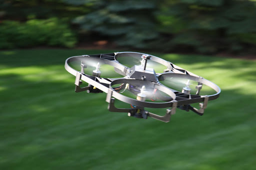
From Matterhackers, a profile of the making of Freebird One, a Pixhawk-powered commercial drone.
Technology and the latest gadgets have always been an interest to me, but they were confined to hobbies during my limited free time as a financial analyst for nearly 20 years. I decided to take some time away from that world in early 2014 after the 2008 financial crisis effects sapped the industry of a lot of the bright minds that had attracted me to it in the mid-‘90s. I was hoping to unleash my creativity in developing something new where I could make a difference, and I was excited to finally have some time to do that.
Naturally, I became interested in 3D printing, and bought a Cubex printer. I began teaching myself how to do basic prints with the out-of-the-box software, but I soon discovered Fusion 360 from Autodesk and was quickly making more complicated designs. First on the list were custom child-safety items like protected wall plates, knobs for stoves, and doors to make the house safer for our twin boys who were 1-year old at the time. I found I could make these items in just the right dimensions to fit the hardware in our house in contrast to generic store bought items that typically fell short of being truly useful.
A couple months later, I got a small drone, another new technology I was interested in, and which were just becoming more widely available. A few weeks after that purchase, like most new drone owners, I crashed it in our back yard and broke one of the arms. As I was trying to locate replacement parts, I glanced over at the printer and it occurred to me I could probably make replacements. Having successfully done that, and learning more about the drone technology in the market at the time, a couple of months later, I thought I’d try to develop something better than what was available – in particular something larger that could be used for all sorts of applications – not just video – and that was more weather tolerant. That was summer 2014.
By early fall, I had a working prototype – made mostly from ABS and PLA. I had also upgraded to a Lulzbot TAZ 4 printer, which opened up a whole new universe of materials that I couldn’t use with the proprietary Cubex platform. That’s when I discovered MatterHackers, which quickly became my single source for filament. In October or November 2014, they introduced Proto Pasta’s carbon fiber filament, which I quickly tried. That was perhaps the biggest enabler for me to develop the current design. I could now print much thinner, much faster, and with absolutely no warping. The design at the time, and which I stuck with for a couple more months after the carbon fiber was introduced, more closely resembled a tradition quadcopter with four arms. Even with the carbon fiber, I still had problems with arms breaking off over time because of the heavy load (up to 25 pounds) being carried by the arms in conjunction with vibration from the motors.
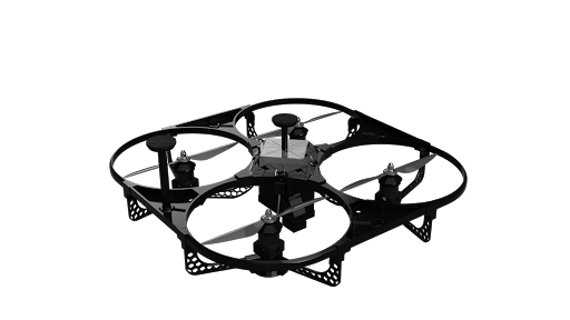
As I became better at printing the carbon fiber and improved my CAD design skills, I decided to overhaul the design completely in order to print even thinner parts while at the same time evenly distributing the weight of the UAV and stress from the motors’ torque all around the frame. The current enclosed frame design came to me one day – I still remember – on a Friday in early January, just about a year ago. The whole picture was in my head. It was to be an airframe that enclosed the blades (for safety), but in a way that actually increased the strength of the overall frame by distributing the vehicle’s weight and motor torque stress evenly to avoid concentration of stress at just four points – something I now call a SurroundFrame. Even until now, I have not seen an enclosed frame design that is anything more than a body cover that sits on top of a traditional frame with four arms – or a variation that has partial enclosures on the outer corners. In any case, while helpful from a safety perspective, they represent added weight that reduces battery and flight time. It took me exactly a week to design and print the whole frame and transfer the motors and other electronics over from the prior design. That following Friday, the 3-foot diameter UAV (now called Freebird One), was in the air.
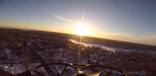
I knew this was the design I was after, but much work was still needed. It was lighter than my old design, but still too heavy. Flight times were 8-10 minutes with large batteries. It weighed 20 pounds or so. The wiring couldn’t stand up to the high current pull. A couple of times it even caught fire in the air! As it was winter at the time, electronics and motors were repeatedly destroyed by flying in the snow. Even so, I discovered the first alternative use for a large UAV with a lot of prop wash: an airborne snow blower. It was good for up to four inches or so of snow and could clear our driveway in minutes operated from inside the warm house! But it could do even more than a regular snow blower. It cleared snow off the cars and then off the roof of our house.
My mission was clear at that point: I had something powerful that could fly very precisely and on its own. But it needed to fly a lot longer, be a lot lighter, handle any kind of weather, carry a lot of equipment and attachments that I might want to develop for various tasks -- and do all this without sacrificing strength. I stuck with carbon fiber for the most part, though successfully produced one unit entirely with wood fiber filament from MatterHackers last summer. Additional materials in the current version include Ninjaflex for weather covers and vibration dampening and transparent Bluprint for the cockpit cover to make the lights from the 3D Robotics Pixhawk flight controller visible.
The bottom line is that numerous iterations and a year later, I have created a 100% printed large UAV from an idea in my head, a fantastic CAD package from Autodesk, a solid workhorse printer from Lulzbot, and high quality, reliable (always 2-day free deliver across the country) filament from MatterHackers, in particular Proto Pasta’s carbon fiber. The only purchased components are the electronics and propellers, though I have successfully printed propellers that work, and may eventually switch to printed props after testing is completed. The UAV is even assembled using printed carbon fiber pins, which replaced traditional stainless steel screws I had been using earlier.
Not only is Freebird One 100% 3D-printed, but I would argue its performance specs beat anything on the market today. It now weighs just 8 pounds without a battery (half of what it weighed the first time I made it). It can fly for up to 35 minutes, has maximum speeds of 70MPH horizontally and 3,000 feet/minute vertically, can carry an additional 15-20 pounds of payload thanks to more 6,000 watts (9+ horsepower) from the four brushless motors, and is completely weatherproof (snow, rain and winds up to 50 MPH or so). It’s also the safest UAV.
My hope for the future is to add artificial intelligence features to assist in obstacle avoidance and expanded failsafe features such as a parachute and ability to find safe places to land in the event of a problem that precludes the UAV from returning home. Equally important, I hope to develop a number of attachments to expand functionality of Freebird One as a useful “tool”. Snowblowing is just one example, but even that could be improved with attachments I have in mind. I also successfully used it this fall as a leaf blower. And because the blades are enclosed, I was able to remove impacted leaves along fences by bumping the UAV along the fence and angling the airflow in a way to get under the leaves. In a similar capacity, the UAV works well as a gutter cleaner with a 3D Camera (in a 3D-printed weatherproof case) sending a live video feed to a pair of goggles, allowing for precise maneuvering in tight spots. The possibilities are endless – both for consumers and businesses.
Freebird One will be commercially available in the near future. After having issued RFQs for injection molded parts, it is not clear that I can get parts made to the tight specs I have been achieved through 3D printing. Given the nature of this project, every gram of weight matters a lot, and in particular the strength-weight dynamic. Every 100 grams represents roughly one minute of flight time, and every gram of material needs to be exceedingly strong. As a result, the current plan is to actually build up a 3D printer “farm” to produce parts quickly. I have improved print settings to the point where the parts coming off the printer require little to no post-processing. At 20 um resolution using carbon fiber, the lines are not very visible and look more like a pattern than what traditional 3D-printed parts look like. Using 3D printing as a manufacturing solution also enables me to revise and improve parts quickly, introduce new attachments, and provide custom modifications without using a typical update cycle.
To date I have been working on this venture alone, but will be expanding in the near future. I really treasure the time I’ve spent on this so far. Not only have I been able to spend more time with my family, but I have been able to just dream up new ideas and then actually produce them right before my eyes. Even more than the UAV I’ve created, I remain amazed at the possibilities opened up by 3D printing and high quality consumer-accessible CAD software. It’s a great age we live in where someone like me with no engineering background can design and produce a high quality aircraft in the confines of my home with nothing more than an idea, a computer, a 3D printer, a few spools of filament… and some patience.

[Edit 12/31/2015: Note for Pixhawk users that Canon cameras require a 5V pulse to trigger so a voltage step-up from Pixhawk's 3.3V output is required. See compatible cable and link to more instructions here.]

This tutorial will show you how to get your CHDK-enabled camera connected to your ArduPilot Mega (APM) without buying any extra hardware or decoding PWM outputs. You might want to make this connection to take advantage of the camera trigger function based on distance covered, to ensure a certain overlap and to avoid excessively high overlap. This modification is not necessary, if you have a CHDK camera and want to keep it simple, you won’t gain much by switching to this method right away.
For this tutorial, I’ll use an SX260 HS but this should work equally well on any CHDK-supported Canon Powershot camera. You’ll need just the supplies below to make the cable. The SX260 uses a USB Mini-B connector. Most Powershot cameras come with a USB cable, you can just use that one to be safe.

If you don’t have a crimp tool to attach the servo connector, just take a spare servo wire and solder the wires together instead.
We’ll only be using the Mini-B side of this cable, so measure whatever length you need from that end depending on how your camera and autopilot mount in your airframe. I’ve measured out about 14″ and cut the cable completely through. Inside are four wires, we only need the red and black wire so cut away the green and white wires. Strip the ends of the red and black wires.

If you have the crimp tool, crimp and insert the wires into the first and third positions of a 3-position header. If you don’t have the crimp tool, solder these two wires to the ground and signal wires of a spare servo wire. Insert the ground wire into the side with an arrow so you can tell which wire is which later on.

Cover the connector with heatshrink. Be careful with the hot air near the connector as it can cause the locking plastic pieces in the receptacle to deform.

Now plug this cable into pin A9 on the side row of APM. The text doesn’t line up exactly so be sure to count rows. SPI takes two rows, then A11 and A10 are two more so there should be 4 rows of free pins, then our new connector.

If you already have CHDK installed, just install the script file (right click, save link as) into the scripts directory on your SD card. If not, follow instructions for installing CHDK from the page corresponding to your camera atthe CHDK wiki. Load up CHDK and go into the menu then navigate to Miscellaneous Stuff -> Remote Parameters and make sure the Enable Remote setting is checked.

Now connect to your APM and open the Full Parameters List in the Config/Tuning tab. Set the parameters as following:
- CAM_DURATION: 1
- CAM_TRIGG_DIST: Depending on overlap required.. be sure to keep in mind the normal downwind speed of your plane as well as the maximum rate at which the camera can take pictures. For the SX260 and the E382 that’s once every 2.7 seconds and about 18m/s. I plan to operate below those condition in most cases but I do like to get as many pictures as possible, so I set my distance to 49 (meters).
- CAM_TRIGG_TYPE: 1
- RELAY_PIN: 13


All that’s left is to test it out. Load the E38_APM.bas script file like any normal CHDK script and start running it. If you can get a 3d fix inside, you can test it on your lab bench just using USB power. Just set the CAM_TRIGG_DIST to 1 or 2 meters and let your plane sit on the desk. Small movements between GPS readings will cause the distance value to count up slowly and it should trigger the shutter every few seconds.
If your camera lens closes and opens instead of taking a picture, make sure the CHDK remote enable setting saved properly. If nothing happens at all, take your APM outside and walk around to make sure you are getting some distance covered.
