All Posts (11086)

Sort by

3689599900?profile=originalHello DIY Drones Universe,

This is Joshua Johnson from CAD Drones, LLC.  I'm here to share with you a FREE LIVE Education Podcast that will be shared on Youtube front page of CADDrones.com, and has a "dedicated forum for discussions"!  As the picture above explains I will be doing "Educational Podcasts" on  various topics such as:

  • Using CAD Software for Drone Projects and work
  • 3D Printing Drones
  • Engineering Concepts
  • Blueprint Reading and Sketching
  • Algorithms
  • Drones
  • 3D Printer Reviews (For Use To Print Drones and Parts)
  • Commercial Drone Reviews from established vehicles in the UAS Industry
  • Using CAD to test electronic setups
  • Using CAD to design your own Drone Hardware
  • CAD Software Reviews
  • and Much Much More!

Episode 1 Goes LIVE Tuesday June 10th, 2014 at 1PM CST (Times Subject To Change):

3689600029?profile=original

Episode 2 Goes LIVE Thursday June 12th, 2014 at 1PM CST (Times Subject To Change):

3689600115?profile=original

Read more…
Developer

Printed high speed AVC copter and crash

3689599934?profile=originalHi all,

I thought I would share the copter I hoped/hope to fly at ACV this year. I wanted to try to see what speeds I could get from a quad. I also thought it would be interesting to see what I could to with a 3d printer. I have access to a Makerbot 2x and I was also adding a heated bed to a friends printer. So based on the maximum dimensions of the Makerbot I designed the quad you see above and rendered below.

3689599982?profile=original

The quad consists of 4 arms with a semi aerodynamic cross section that is angled forward by 60 degrees. The round nose holds a tennis ball and the bottom swings open using a servo to drop the ball. The battery is held in the center of the frame and the 4 esc's are recessed into the side of the body to provide them with cooling without adding too much drag. The copter is held together using screws and nylock nuts that are pressed into the plastic.

I did some basic calculations to try to get an idea of what angle I was going to be able to sustain. My calculations suggested that I should be able to maintain 60 degrees if the air frame drag stops the copter from moving fast enough to reduce the lift of the props. I found I had to make some guesses about the air frame drag (I used coefficient of drag of a tennis ball as a starting point) and the area of the copter (I think this may have been a little low). In the end I concluded that without wind tunnel testing and a much better understanding of propeller aerodynamics I wasn't going to get too much out of the calculations.

What I did get was a reasonable estimate of the power I was going to need from each motor, 700 W total or 175 W per motor. This was well below the 285 W the NTM 28-26A 1200 kv motors are rated at. It also looks like it may be easier to get higher speeds as the weight of the copter increases. This is because the increased weight means the copter must hold a lower pitch angle at a given speed because of the increased lift required to stop the copter from loosing altitude. I limited my pitch angle to -60 degrees to ensure the copter didn't get too close to gimbal lock. The calculation of the airflow angle over the arms as speed increases and the copter pitches forward. What I found is the airflow becomes dominated y the forward airflow very quickly. In my case the airflow is only 3 degrees off the 60 degree angle of the arms at maximum speed.

3689599873?profile=originalSo I did an autotune and took the copter out to the local model club to see what I could do. I found the copter would accelerate very quickly and the frame was amazingly strong and ridged. While the flame wheel frame I tested the power train on would bend under full acceleration, the 3d printed frame was a rock. With the 45 degree maximum pids I couldn't take the throttle past about half way without climbing. So I checked over the logs for any obvious problems (other than the one I had) and increased the maximum angle to 60 degrees. I also found that I had to adjust the yaw pids to control the frame a high speeds because it wanted to turn the frame sideways to the airflow. This is a well known effect. Just shoot an arrow without feathers or fire a rocket without fins. I was able to adjust the yaw pids to keep the copter right where I wanted it in the following flight.

The following flight I was able to really wind it out. I was very happy with the performance of the copter. It wasn't getting up to the speeds I was hoping for but things were looking good. After about 3 minutes of high speed passes I saw a clear line of white smoke coming from the copter followed by...... unhappiness.

3689599997?profile=originalThe front left motor was burning hot and the smoke was the insulation on the winding's burning off. The logs showed that the front left motor was pegged during each high speed run and there was obviously a problem with it. The logs also showed maximum velocity of 107 km/h but it was happy sitting at 90 km/h even into a small head wind. The props / motor / battery combination would max out at 126 km/h on a normal plane.

So overall I was pretty happy with the performance. And I can say that a quad can be very effectively 3d printed provided the arms are designed to take advantage of the strengths of 3d printing. In this case each arm and body section attached to it was 70 g. The strength was high enough such that I couldn't break a arm by trying to bend it in my hands.

So now I need to work out if I can print a replacement before I fly to AVC. I need to print 6 parts, each taking approximately 12 hours. So each is an overnight print and I have 6 nights before I need to leave.... I may need to fly the Y6 :(

Things to remember. (this is a "note to self" but I thought I would share)

Always check the position of the bell on the motor shaft and adjust it to get the optimal location. This problem sounds like a bearing problem in flight. This is also a good time to ensure the grub screw is tightened properly.

After the first flight check the motor output of the autopilot at maximum throttle to see if any motor is consistently maxing out before others. This is the tell tail sign of a motor or esc problem and would have saved me here. I didn't look at this because all the motors were brand new.... bugger :)

Always check every screw and prop before the first flight. This is where little things can go wrong.

Yaw stability in a copter will take a big load of the yaw controller in a high speed copter.

Read more…

The sPRUnal chord of Beaglepilot

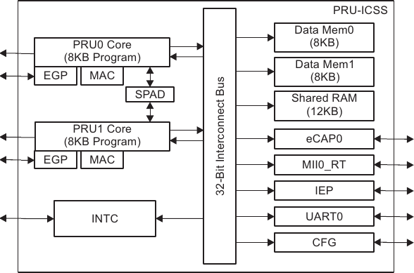
PRUSSAn Axiom: You just can't make your unmanned vehicle of any use until all its actuators respond correctly. Which means there should be enough means, i.e. PWM ports in ardupilot's case ,to control them correctly. How can this be achieved on a linux machine(BeagleBone (Black))with just six PWM channels. You don't just want your unmanned vehicle to travel (well you may require more than six channels for doing that too), you require PWM for many things and we can start our list with operating camera gimbal. Software PWM on a Beaglebone is close to unthinkable, even 20-50us of latencies in toggling PWM pin can lead to your beloved vehicle's devastation, and can even cause harm to you and people around you.One way is to add another hardware to generate as many PWMs as you want. This can be the way then, you might wonder. However, it is rather better if you can do everything with as few things as possible. So here comes the PRUSS(Programmable Remote Unit Subsystem) in the picture. There are two PRUs in am335x microprocessor , lets call them PRU0 and PRU1. The beauty of this system is that the three cores: ARM core, PRU0, PRU1, act as conjoined triplets. Except the general purpose registers, each and every part of there memory is mapped to each other's memory. For example I can very easily access GPIO peripheral belonging to ARM core via PRUx and toggle them, leaving linux kernel running on ARM core asking to itself "who is trying to play with my things?" but it will never know. Well, i guess you all agree its not a pretty thing to do. Don't worry we will not trouble our sweet kernel as there is another tool which PRUSS technology has got in its arsenal: All the bits of General Purpose register R30 are mapped to physical pins. So there you go, you just got 32*2 i.e. 64 pins waiting to be acting as PWM channel with resolution as low as 4ns. Also, If you don't mind troubling linux kernel and a few 100ns latencies are fine by you, you can convert each and every GPIO pin into a PWM channel(but i don't think anybody will be required to go that far).Many of you might have started asking questions to yourselves, well why not just port ardupilot to PRUSS cores rather than ARM core seeing it is so powerful? PRUSS is no doubt a very fast core running at 200MHz but it has very little memory, only 4Kb Program and 8Kb Data RAM: you can't even fit in a printf code with floating point support into PRU's PRAM. PRUSS in beaglepilot system is being utilised like our Spinal Chord. They will do any menial recursive tasks like generating PWM or may be if required collect and pass timestamped sensor data but they can't be utilised for major data crunching or storing purposes. Therefore any task which has very small memory requirements but require not only hard realtime but also very narrow execution time is to be thrown towards PRU to handle.So I guess this post, at-least in part, answers some of the questions like: Why use BeagleBone Black platform? How PRU is useful to the Beaglepilot project? But leaves you with the question: How it is actually being implemented inside Beaglepilot? I'll leave you all with this question until next time.Regards,Siddharth Bharat Purohit
Read more…

3689599763?profile=original

Yesterday at BeaglePilot's weekly meeting we had great progress :):

  • We got readings from the MPU6000 (SPI) and MS5611 (SPI) from the AP_Linux_HAL.
  • We made ArduPlane and ArduCopter work in the BeagleBone (we didn't finish the tests with APMRover2 but i'd guess it should be fine as well).
  • We interfaced MAVProxy with ardupilot running on the BeagleBone :)

3689599673?profile=original

There's still much work to do but we are happily moving forward.

In the following weeks you can expect the following to happen:

  • More ardupilot hardware tests and drivers will come out. We are happy to have Jimmy Johnson and Daniel Frenzel with us doing a great job coding kernel drivers.
  • A new Device Tree for our hardware.
  • ROS integration and tests through MAVLink (using the already available mavlink_ros ROS package). We will also look into the possibility of coding a ROS bridge directly into ardupilot.
  • Improved PWM and PPM generation using directly the PRU.
  • ROS-ardupilot tests and performance report.

We will also be testing the Real-Time capabilities both in hardware and software. Here you have some first results. We will try to continue reporting about it.

Read more…
Moderator

In this video you can see the first fly review of VRBrain micro 5.0 

In this test you can see the great quality of new magnetometer and gps . Emile doing an automatic fly . Set by VR Pad Station 3 waypoint , the last is an RTL . The drone take off from Emile's hand then land exactly in same position :) Emile don't move from his position during all the automatic fly test :)

Dear Friends,
I worked hard in recent weeks to test the new micro VRBrain 5.0
To test the card I used the frame I called our "Personal Robot SDK Fly" The configuration I used for testing and 'the following:

Frame VRX AV250 with Prop Guard
- Micro VRBrain 5
- VR GPS Ublox LEA 6
- 4 10 Amp ESC with Firmware SimonK
- 4 2400 KV Brushless Motors
- 4 Carbon Fiber Propeller dda 5 inches.
- 1 Battery 2200 Mah
- Receiver Futaba SBUS R7008 SB.
- Transmitter T14SG.

During the tests I carried out flight tests and reliability in a stable manner. I flew in different boundary conditions without having any kind of reliability problem. I made flights in both indoor and outdoor.

End the tests with flight manual I started  the automated flight test . The GPS took our new GPS  VR GPS uBlox LEA6, the main feature of this GPS and 'to have on board the new sensor HMC 5983 with automatic temperature compensation and more accuracy and immunity to electromagnetic interference.

In the tests we performed automated test of loiter mode, hybrid loiter, return to home and  waypoint navigation.

Given the excellent results of the tests we have decided to close this firmware revision of the first software will be installed on the cards that will come over the next week.

More info about the components of the test are available here:

http://www.virtualrobotix.it/index.php/en/shop/autopilot/vrbrainmicro51-detail

http://www.virtualrobotix.it/index.php/en/shop/accessories/3dr-gps-ublox-lea-6-30-37-detail

original blog post : 

http://www.virtualrobotix.com/profiles/blogs/vr-brain-micro-5-0-vrx-personal-fly-robot-sdk-the-perfect-fly-pla

Best

Roberto

Read more…
3D Robotics

ArduCopter 3.2, which is now in beta testing, has an awesome new spline navigation feature, which creates smooth curves between waypoints (thanks to David Dewey, with help from Leonard Hall and Randy Mackay). One advantage of this is that you get really smooth camera angles, as the copter gracefully turns and points itself at the designated Region of Interest.  

Check out this video, which shows it to great effect. 

ArduCopter 3.2 will be released to all users in late June, after Sparkfun AVC (the final stress test!)

Read more…
Moderator

3689599533?profile=original

In this picture is possible to see the position of main airport in the silicon valley with 4 miles of buffer around the position of airport. Our idea is to activate an a default automatic function that when the user try to fly in that area activate immediatly a landing failsafe procededure . 

3689596642?profile=original

VR Pad Station is an app that turns your Android smartphone or your pad into a ground station combined with a powerful digital remote control radio for use with your RC model or with your drone. 
Is designed to be used on Rover, Airplane or Drones for hobby and professional use. It 's a project dynamic and evolving based on feedback from users of our community: www.virtualrobotix.com
It use mavlink 1.0 and support the firmware APM Copter , Plane and Rover

The current version is a preview suitable only for BETA testing use it carefully.
Use VR Radio only with the simulator, until new updates. This software is a valid alternative at DroidPlanner or Andropilot application. Developed inside VR Lab by Virtualrobotix community.

Version 2.0.5

- Added radio calibration in GCS settings;
- Added airports locations on map, in an area of 100km from user/drone position, activated from map settings;
- Fixed minor bugs;

Version 2.0.4

- Corrected gimbal settings layout on smartphones
- Added waypoint commands
- Long click on a waypoint in the list opens an editing dialog
- Option for setting the zoom when auto-pan is enabled
- Added option during the generation of polygon for set the altitude
- Added, where available, range/units/values of parameters
- 3D map in some areas with normal map type
- Now you can interact with map in the VR Radio, if RC override is not enabled
- Fixed an error in VR Radio where the channels goes directly from RC_MIN to RC_MAX
- Added failsafe and sensors status into HUD
- Added HDOP indication in the action bar

In the new revision 2.0.3 is available

  • A new info bar with a lot of usefull information battery level , gps status , active mode .
  • A new follow me standard mode .
  • Only one connection for different application.
  • Parameter setup for gimbal.
  • New configuration option pannel .
  • New advanced user interface compatible not only with PAD but also with Smartphone android device.
  • A early revision of VR Glass Station a special revision that work on Google Glass device.

We are work in progress with some advanced features as Special follow me mode , Fligh log book and VR Gimbal integration.

The App is compatible with APM Copter , Plane and Rover.

Inside the community could be possible discuss directly with developer about the new request feature .

Join us in beta testing this is the direct link to google store : 

https://play.google.com/store/apps/details?id=com.laser.VrPadStation

 Google Community Group for manage the beta testing of VR Pad Station continue to join new member  this is the link : 

http://plus.google.com/communities/102697330643558260161

This is the official Virtual Robotix Discussion group about VR PAD Station 2.0.3 :

http://www.virtualrobotix.com/group/vr-pad-station-2-0

Feedback about our application are welcome ... :) In the next week we intend improve a lot the application with new feature under development.

Best

Roberto

original blog post : http://www.virtualrobotix.com/profiles/blogs/vr-pad-station-2-0-5-for-pad-and-smartphone-support-apm-pixhawk-a

Read more…

My aluminum Nexus 7 TX mount


3689599608?profile=originalEbay was running a great deal on refurbished 2nd gen Nexus 7's, so I thought it would be a great time to step away from my HoTT telemetry (and the headache of constantly making the module work with the arducopter code) and upgrade to DroidPlanner2 and the new 3DR radio!  

There were a few posts about people doing this, with some very great ideas with varying complexity. Hobbyking also has a carbon fiber solution for this (I ordered, but decided I couldn't wait).

I am in the process of building myself a CNC (but I also couldn't wait to be finished with that). The mount is pretty simple, I have a lot of aluminum flats of varying sizes that I got from Lowes for some frame builds, with a little bit of measuring, a pencil, bandsaw, sander and file I crafted this.  It turned out to be very rigid, even without any horizontal bracing.

More at my project blog!

3689599569?profile=original

3689599594?profile=original

Read more…

3689599649?profile=original

Our Vulture 2 spaceplane's miniature pilot - the plucky Playmonaut - had a narrow escape earlier this week after one of the aircraft's servos went up in smoke during testing.

As you can see in the above photo, emergency teams rushed to the scene, while we were left to ponder what caused the meltdown. The remedy might require the old Zener clamping diode ploy, and if that's so, then we're pretty well done on finally firing up the fully-assembled vehicle.

Next on the agenda is getting the Pixhawk to talk to the onboard Raspberry Pi, after which its mission parameter programming time, which promises to be a stiff-brandy-heavy task.

Read more…

3689599241?profile=original

Please check out part one of this blog series here!

There has been a remarkable amount of work to do between receiving all of my parts and getting to this stage of the build. However the Smart-Drone is starting to take formidable shape...

Project Overview

The goal of this project remains the same: To put into practice all of the wonderful techniques and tips that I have acquired during my tenure at DIY Drones. The goal of this build is to not only produce a functional piece of equipment but also a work of art...

The main project criteria are:

  • Easy maintenance (a modular design)
  • Advanced functionality (thanks to Arducopter)
  • Reliable operation
  • long flight times ~ 20min
  • the ability to carry a nex 5/7 camera and Gimbal for aerial videography (800g-1kg)
  • Stable flight even in light winds
  • Low vibrations
  • Low signal and magnetic interference

In terms of wiring and layout, the drone design is largely based on my infographic that I previously created for the community here: Pixhawk Infographic

Some design considerations that have since been improved upon mainly concern the radio system. The fact that I am using the FrSky D4R-II PPM sum receiver and the newer Turnigy 9XR with a DJT module and small lipo battery should reduce points of failure and simplify things.

Considering that this will be my first completely autonomous drone I am erring on the side of caution by carefully following the Arducopter wiki in a linear fashion.

The arducopter wiki is exceptionally clear and well presented so It's hard to go wrong if you follow along and pay attention (an increasingly rare commodity)!

Getting Started

My first priority was to start filling the partially assembled frame with power guts.

I decided to keep the high current components restricted to the center of the carbon fiber frame to prevent any interference. The X650 is a well thought out frame in that respect and the carbon fibers should do a decent job of shielding rogue wavicles.

I made use of a 25 amp 4 in 1 ESC because it removes the need for a power distribution board and mitigates RF interference.

Due to my Motor and Propeller combination (12" props with 710kv 2814 motors on a 4S system) I will be running the ESC a bit on the high end. I therefore decided to mount it facing down and thermally coupled the ESC heatsink plate to the main carbon fiber frame plate.

Initially the four in one ESC motor wires were far too long and, in combination with the motor wires, added unnecessary weight. So I cut them to length and re-soldered them to the ESC board.

3689599320?profile=original

After mounting the ESCs I proceeded to connect the motors and check that their rotations matched the diagram on the motor setup wiki page.

To further shield any interference from reaching the Pixhawk Flight Controller I mounted a carbon fiber plate on top of the upsidedown ESC.

The Pixhawk itself is powered primarily through the Power Module (PM) however the 4 in 1 ESC provides a secondary source of power through the servo connections. This is perfectly safe because the Pixhawk has a clever power management system that selects the most healthy power source (in my case the power coming from the PM).

Then I mounted the PM next to the ESCs, close to one of the holes in the bottom frame plate so that I could attach the Lipo battery.

Finally I soldered up the XT60 connectors to the battery and 4 in1 ESC. In the image below you can see the finished power system in place.

3689599283?profile=original

Since then I have added a cable sheath to the power module wires so as to prevent wear and tear after repeated plugging and unplugging.

After making sure that all my motor spun in the right direction I could finally assemble the main frame using threadlock.

It is always important to check that the arms and motors are perfectly level after assembly. I did this with a bubble level and will check again later using a smart-phone app.

In addition I also balanced 8 Carbon Fiber propellers which you can read more about here.

Adding the smart stuff

Next step was to mount the Flight Controller and receiver plus pixhawk accessories.

3689599378?profile=original

Here you can see the Pixhawk, GPS and D4R-II reciever. In addition I added the I2C splitter in a convenient location, mounted using adhesive foam, for future upgrades.

I mounted the Pixhawk using the provided foam standoffs. Hopefully this will be enough to isolate any unwanted vibrations. This is yet to be fully tested.

I took care to ensure that the flight controller was in the center of gravity of the aircraft.

The GPS and compass module is raised up far away from any magnetic interference. I used the X650 mounting clip system to mount the GPS. I do have concerns about magnetic interference from the GPS case screws and the actual mount itself though.

I also had to extend the GPS cable for it to reach the pixhawk.

I then attached the safety arming switch to the top bug shell for easy arming/disarming and finished the external wiring with heavy duty wire braiding...

3689599345?profile=original

Next step was to power her up for the first time...

I set up the transmitter by first plugging in the DJT Module to the back of the transmitter. Next I plugged in the lipo and performed the binding procedure.

After power-up everything seems to be in working order!

With everything connected I can now use mission planner to begin programming the smart drone for it's first of many flights!

Part three will include more on the software side of things and detail how I have setup my parameters and fine tuned the smart-drone...

Jethro.
Read more…

I was recently given the opportunity to play around with the world's smallest production quadcopter, the Cheerson CX-10. While the title is certainly not given by Guinness, this quadcopter does unofficially measure in slightly smaller than the previous self-proclaimed title holder, the Estes Proto-X.

3689599471?profile=original

3689599502?profile=original

This quadcopter is also CHEAPER than the Proto-X, coming in at under $25 US. The protocol for the radio controller has already been discovered. It uses a one of the standard RC model protocols, meaning modules and programming to get it working with Devo radios running Deviation firmware has already been completed. As a result, full-size controllers, capable of receiving PPM input through a trainer port, can control this quadcopter. This opens the possibility of a cellphone, tablet, or computer being used as an input device. Ultimately, the control module could be hacked to run direct from a computer, and, "replacement," bind and fly versions of this little multi without transmitter could come in just over $15 US according to an email I received in response to that query. With quads this cheap, and a potential easy interface to a computer, I could see people setting up their own miniature version of the Flying Machine Arena in basements and spare bedrooms. In fact, as I flew this quad into and out of the indoor trampoline, with a safety netting around it several feet high, this idea popped into my head! Maybe someday little swarms of robots will be computer guided around my kid's basement playroom. I am sure they would love that. The wife...maybe not.


Read more…
3D Robotics

3689599305?profile=original
There's a new 92-page report from the National Research Council on the next research priorities to allow drones to safely operate in the national airspace. (USA Today reports on it here).  It's available, free to read, here.

I couldn't help but notice this passage, on page 64, regarding DIY Drones and open source UAV projects such as ours. Do you agree with this assessment?

There are also positive indications of coordination in the recreational, or hobbyist, unmanned
aircraft community. There are many Web sites that share of open-source software and hardware, with
open forums that enable widespread sharing of ideas, techniques, and methods for achieving IA
operations of small, amateur-built UAS. However, these activities are largely undertaken without
consideration of issues such as certification and thus are generating designs and approaches that might be technologically advanced but that could be certified for proper, approved operations in the civil aviation system only with great difficulty, if at all. Since these systems are not verified or validated for such  qualities as robustness, completeness, and fault tolerance, the ultimate contribution of this sector to the advancement of IA systems in the NAS remains to be seen.

Read more…
3D Robotics

3689599091?profile=original

From the University of Cincinnati, a research delivery drone project based on an Pixhawk-powered octocopter with an innovative modular design (via Fast Company)

drone flying
The HorseFly drone was developed as a result of collaborative efforts from the University of Cincinnati, AMP Electric Vehicles and the University of Cincinnati Research Institute.


The University of Cincinnati and AMP Electric Vehicles, makers of the WorkHorse all-electric delivery truck, collaborated on the HorseFly "octocopter" through an innovative partnership made possible by the University of Cincinnati Research Institute (UCRI).

The newly designed, autonomous unmanned aerial vehicle (UAV) was developed to work in tandem with AMP's delivery trucks, creating a safe, fast and never-before-seen method of delivering goods.

Steve Burns, CEO of AMP, explains the process like this: The HorseFly will be positioned atop a delivery truck, awaiting a package from the driver. When loaded, the HorseFly will scan the barcode on the package, determine the path to the delivery address via GPS and fly away – completely self-guided – to the appropriate destination. Meanwhile, the delivery truck will continue on its rounds. After successful delivery, the HorseFly will zoom back to the truck for its next delivery run and, if needed, a roughly two-minute wireless recharge.

"Our premise with HorseFly is that the HorseFly sticks close to the horse," Burns says. "If required, the HorseFly will wirelessly recharge from the large battery in the WorkHorse truck. The fact that the delivery trucks are sufficiently scattered within almost any region during the day makes for short flights, as opposed to flying from the warehouse for each delivery."

Paul Orkwis, head of UC's Department of Aerospace Engineering and Engineering Mechanics, looks at the HorseFly and sees its potential to be something more.

"If you want to get really far-fetched and look into the future, at something like a flying car, that's possibly what you could be looking at with this," Orkwis says.

NEW AGE OF AIRMAIL 

The UAV-truck delivery method is an ingeniously simple concept powered by some very complex technology. UC aerospace researchers have developed an experimental capability to capture the dynamic behavior – response to outside forces, such as wind gusts – of the UAV platform. 

The researchers use computer models to analyze how a UAV behaves in a dynamic environment, allowing them to develop an autonomous controller and essentially put the UAV on autopilot. Flight tests have shown UC's modeling system to be highly accurate. 

researcher holds drone
UC's Wei Wei holds the HorseFly drone, which features a sophisticated autonomous controller system and multiple built-in hardware redundancies.


The novel, reconfigurable design of the HorseFly UAV is a product of this research, says Kelly Cohen, an associate professor of aerospace engineering and engineering mechanics. Cohen's team is led by his PhD student Wei Wei with support from fellow students Bryan Brown, Nicholas Schwartz, Vince DeChellis and Nathaniel Richards.

"With the HorseFly project, we developed a brand-new aircraft and airframe from scratch, and we built the system with the ability to look into different applications. Now we can build a family of octorotors and find out the best possible configuration," Cohen says. "There is no textbook on multirotor aircraft design. Here we have been pioneering this effort, and we've come up with something successful."

EXPERTS ON FLYING SAFELY

Key to that success and a primary reason AMP teamed with UC has been the researchers' ability to make the HorseFly safe and resilient. In addition to the sophisticated autonomous controller system, the HorseFly will have multiple built-in hardware redundancies (rotors, onboard computers, battery packs). So if, for example, multiple rotors were to fail, the HorseFly and its payload still could be retrieved safely.

"An important part of the HorseFly project is that we make a vehicle that will not drop out of the sky," Burns says. "This is the particular point that UC specializes in and where we are relying on their expertise to help us build such a safe and resilient craft."

Burns also noted that the HorseFly can be supported by human pilots in a flight control center who can access the aircraft's cameras to choose the safest landing spot.

STRATEGIC PARTNERSHIP WITH INDUSTRY

The partnership between UC and AMP was secured through UCRI, an independent nonprofit entity connecting UC experts to industry partners, facilitating commercialization of research and enhancing experiential learning for UC students.

For HorseFly, Burns connected with Orkwis to explain his vision for the project. Then an agreement was developed in a matter of days with help from UCRI CEO David Linger. 

drone before takeoff
HorseFly, a newly designed, autonomous unmanned aerial vehicle, was developed to work in tandem with AMP's delivery trucks, creating a safe, fast and never-before-seen method of delivering goods.


“UCRI supports businesses, small or large, that want to access and leverage the university’s expertise: faculty, students and labs to collaborate with the firm’s researchers,” Linger explains. “The partnership with AMP is a great example of how UCRI can facilitate the path to innovation between private industry and university resources.”

According to Linger, partnerships between the university and private businesses have traditionally been limited to the co-op program or privately-funded research, and were often complicated and time-intensive to undertake. But because it is an independent, small nonprofit, UCRI can leverage the full expertise of the university while executing with agility and efficiency. 

Cohen said working with UCRI has opened new doors for his department.

"AMP came up with a vision, and we made suggestions. Those suggestions were translated into a very quick project, something that would have been impossible without UCRI," Cohen says. "Now, we have the possibility of becoming strategic business partners working with industry, pushing the envelope together as we transition technology as well as business ideas due to our knowledge of the market."

Terms of the agreement called for AMP to receive a working, flight-tested design prototype, and a final report and demonstration. AMP provided funding for minimal overhead costs and tuition support for Wei.

Orkwis credited UCRI for streamlining the process and accommodating student involvement in the project. He says the importance of Wei's role was exemplified at a recent flight demo where Wei piloted the HorseFly for AMP investors – a unique real-world experience that is Cincinnati Smart.

"A lot can be attributed to Wei's own can-do attitude. That's really what it comes down to. If you sit back and say, 'No it can't be done,' then who wants to come and work with you?" Orkwis says.

UC and AMP will continue to develop the HorseFly project in anticipation of new Federal Aviation Administration regulations on commercial use of unmanned aerial vehicles. As of now, limited recreational use of UAVs is permitted in the U.S. but commercial activity is not allowed. New FAA rulings are expected soon and could arrive in 2015.

Read more…

3689599184?profile=original

This is Part 1 in a two-part series that summarizes my views on why video/film/cinema – not agriculture and farming — will be the largest driver of sUAS commercial businesses. In this part I explore thoughts on the market for video/film/cinema, and below I outline why I believe film and video will lead in market uptake. In Part 2 I’ll outline why I believe agriculture will lag in market uptake.

A total economic impact of $13.6 billion and 70,000 new jobs in the first three years. That’s the forecast for what drones will bring to the U.S. once regulations are in place, according to a March 2013 market study produced by the Association of Unmanned Vehicle Systems International (AUVSI). The report entitled “The Economic Impact of Unmanned Aircraft Systems Integration in the United States,” goes on to say that precision agriculture and public safety will make up more than 90% of this growth. Most important, the report confidently states, “…the commercial agriculture market is by far the largest segment, dwarfing all others.”

These figures get repeated over and over again in the media and across the blogosphere.  Existing players and potential new entrants in the UAV market are betting their business futures – and in some cases their entire family’s income and savings – on them.  Everybody wants in on the action.  But are the media, blogosphere, and AUVSI reports correct? I have some serious doubt. Here’s why:  The numbers from my recent study on the impact of Federal Aviation Administration (FAA) rules on the small UAS business say aerial photography and cinema – not agriculture –dominate the other vertical markets and will continue to do so for some time. This two-part post looks at those two industries – film making and agriculture – and attempts to separate market forecast hype from the reality by looking at detailed numbers, market forces, and the specific applications themselves.

Read more here: http://droneanalyst.com/2014/06/05/drones-for-film-and-farm-which-is-the-bigger-market-part-1/

Read more…
3D Robotics

3689599066?profile=original

Thanks to John Githens for pointing us to this fascinating post from the Center for Robot-Assisted Search and Rescue at Texas A&M about why they weren't allowed to fly emergency response drones at the recent Washington mud slides:

Just returned from the Oso, WA, mudslides with the Field Innovation Team (FIT) but didn’t fly due to drone privacy concerns from Snohomish county. The upside is that we now have a template for manned/unmanned airspace deconfliction and can assist others in getting emergency certificates of authorization (COAs ).

We had requests from the county to fly small UAVs first thing on Thursday but it was Friday morning before we had three assets on site: two fixed wings (the Insitu ScanEagle, Precision Hawk Lancaster) and one rotorcraft (our Air Robot 100B). All of these were provided through our Roboticists Without Borders program at no cost to the county, with Insitu and Precision Hawk diverting their teams led by Kevin Cole and Pat Lohman respectively from their current jobs.

The reason for UAVs was straightforward. Responders such as WA-TF1 and WA-TF4 working on the rescue and recovery are at great risk from even a small slide or flash flooding as the river is continuously changing and ponding as the rains continue. The site itself is gooey mud and workers would have to be evacuated by helicopters hoisting them out. The canyon is narrow with trees and thus it is hard to get complete imagery from manned assets to predict landslides or manage the flooding. Geologists are gently swarming the edges of the slides setting up sensors but there is still some visual information missing. The ScanEagle and smaller Precision Hawk are world class for geospatial reconstruction and flooding. FIT had arranged for post processing of the AirRobot quadrotor imagery with new 3D reconstruction software from Autodesk. Chief Steve Mason, West Division, talks about the potential for UAVs in this article. We also got a shout out in general.

We worked with the Engineering Branch to determine flight paths and payloads to monitor the river flooding and to get 3cm per pixel higher resolution scans of the lower slide, the cliff face where geologists where having to rope themselves off to take measurements, and the “moonscape” area of the slide currently inaccessible by foot and thus the response teams couldn’t plan how to access. The team went with the Engineering Branch out to the site to refine the missions, identify launch and recovery areas, and how to maintain constant line of sight.  Insitu had to pull out on the first day because we couldn’t find a satisfactory launch and recovery space within the Temporary Flight Restriction (TFR) area, which is airspace over the incident.

The need for the manned helicopters to fly at a moments notice for emergency evacuation combined with regular manned missions and the narrow canyon presented some challenges. Manned helicopters are extremely vulnerable when flying at low altitudes, and even a large bird can take them down, see the article about a near miss. That’s why a TFR is set up and it automatically bans any aircraft including UAVs operating under hobbyist rules. Everything has to be coordinated through the Air Branch of the incident.

The Air Branch instead of just saying “no” to UAVs did the opposite—they welcomed us and did a fantastic job of coordination, with Bill Quistorf helping us create a jargon-free airspace deconfliction plan that should work for just about any incident. Randy Willis and Mark Jordan at the FAA stayed on call through out the weekend working on the emergency COAs for each platform.  Chief Harper gave us a room in the Oso Community Center next to the Oso Fire Station to stage in and we were touched by the generosity and community spirit of everyone we met.

However, as the Operations Branch put in the formal request for the finalized missions and we got ready to fly late on Saturday, Snohomish County Emergency Management in Everett stepped in and blocked the request. After discussions on Sunday, the new Incident Commander Larry Nickey cancelled the missions based on concerns about privacy. The families were already worried about the media leaking photos and some were very contentious about drones. It was at that point that I recalled that Washington state has some of the most restrictive drone anti-privacy laws in the country, so there is already distrust in general.  There was no way for the Engineering Branch to determine without flying the UAVs if the data would be sufficiently better than what they were getting now and would significantly increase the safety of the responders to justify overruling the families. This just wasn’t the time to go into the chain of custody of the imagery or that these were no different than imagery than from the unmanned systems; the families in their grief can’t hear and the EOC personnel shouldn’t be distracted continuing to push for activities that make the families uncomfortable. Larry made the tough, but understandable, call to cancel the missions, but left the door open for flights after victim recovery was complete and the activity was cleanup and reopening the area.

This was the first outing of Roboticists Without Borders with FIT. FIT is lead by Desi Matel-Anderson, former Chief Innovation Advisor for FEMA, Rich Serino, former FEMA Deputy Administrator, and Tamara Palmer, former Program Specialist with FEMA’s Recovery Directorate, to help communities get innovations that they may not be aware of or know how to access. FIT staff worked to understand the needs of local officials and connect us with Autodesk.  Frank Sanborn served as the FIT coordinator for us and he and Stacy Noland get big shout outs for helping with everything from lugging gear and driving 120 miles on Sunday between Everett, the EOC, and the site to try to get the mission request unstuck.

We are disappointed that we can’t help out but our hearts and prayers go out to the families and all of the fine people working this very, very tough event.

Read more…
3D Robotics

3689599167?profile=original

The Journal of Bioinspiration and Biomimetics has a special issue on bioinspired drone control. Chock full of fascinating stuff, most of it free to read. 

Special issue on bioinspired flight control

Preface

Special Issue Papers

Read more…
Moderator

Turnigy 9XR Pro Transmitter Released

9xr_ft(1).jpg?width=300

The Turnigy 9XR Pro has been released by HobbyKing.  I've been beta testing it, and it seems like a pretty good radio.  Here's a couple of pages of information I put together on it, including a video tutorial done in cooperation with the development team.

http://eastbay-rc.blogspot.com/2014/06/welcome-to-turnigy-9xr-pro-video.html

http://eastbay-rc.blogspot.com/2013/10/hobbyking-9xr-pro-notes.html

It's based on the much-admiredSky9x board which has been discussed here before.  I'm excited to see another er9x based radio on the market.  It's fully open sourced, ARM Cortex M3 based, and has all the nifty features you would expect.  It has several open connection sets on the board, and was designed by skynorth to be open to hardware hacking as well as software hacking.

It's interesting to see how much open source development is moving to ARM.

Read more…