All Posts (11086)

Sort by

3689597781?profile=original

Let me ask you, what is the difference between the two?

Do not go for the obvious like size and color, both batteries are the same width and height but the white one is less than half the length.and about half the weight as well.

They are also both the same voltage, but the brown is 14v 3000Mah

the white one is 14v 4000Mah.

In case you didn't know these are lithium Ion batteries.

They charge to the same voltages and discharge to the same voltages, they can be used with the same chargers as lithium polymer batteries but as you can see are much smaller and more durable.

This is because they are similar to AA batteries, they have a metal casing.

This means any crashes are less likely to kill your battery.

So I will be building these packs to sell on for you guys.

You can build them yourself if you like just have a google for some sources to buy the cells from.

I am planning to sell 4500Mah 4s  size wise they are a tad smaller than a 2200Mah 3s Lipo and a bit lighter.

I am aiming to sell them for about £8-£12, a equivalent lipo

(cheapest on hobbyking was £21.50)

And 4s 1000Mah

This is about half the size of the white pack above.

The reason i wont be selling the white pack 4000Mh 4s is due to supply issues but i may in the future.

but in the future i want to expand

3s 45000Mah 

3s 4000Mah

and custom batteries will also be on the agenda.

If you are interested in these packs, have a look on blog history, another member of DIYdrones has posted about them previously,

and if you would like to buy a pack now, i will start selling the 4500Mah packs in about 3 weeks after further testing and built technique experimenting.

Just PM me.

Read more…

3689597726?profile=original

This is a reasonably compact, linearly polarised and well behaved antenna, with a gain , when well made, of around 1dBD    ( 1dB more than a dipole). It is smaller than the Big wheel and the Skew Planar wheel, and I have used it very successfully on 868MHz on our SurVoyeur UAV.

It is derived from a 1/2wave ring, located some distance above a large conducting ground plane. The ring is at a point on its circumference shorted to the ground plane by means of a conducting copper strap. The coaxial cable feed line has the center conductor attached to the ring a short distance away from the shorting strap, and its braid shield connected to a corresponding point on the ground plane. directly below the center conductor connection. The Antenna radiates from the gap between the ring and the ground plane - a Slot radiator antenna. Since the ground plane is inconvenient, we can 'roll' it up into a cylinder, the same diameter as the ring, located coaxially directly below the ring. The antenna performance remains intact. However, the long cylinder is just as inconvenient, so we shorten it till its length is the same as the thickness of the wire forming the ring, and the end result is the picture above. Two concentric rings, spaced apart by plastic insulators, with a 4mm wide copper shorting strap, and the feed coax in place. When the dimensions are proportioned correctly, the antenna gives 1dB gain over a dipole, and when laid horizontally, has a vertical radiation pattern identical to the dipole, with a slight null in the direction of the shorting strap.It is linearly polarized.

For 433MHz, the antenna dimensions shown will give an SWR of 1.1:1 at 433MHz, and 1.25:1 at 429MHz and 437MHz

3689597748?profile=original

Seen from the side :

The rings are 100mm diameter, 2mm clean copper wire, no plastic insulation.

The plastic insulators can be Servo push rod tubes, or any plastic tube or solid rod, about 6 to 10mm diameter, and about 20 to 25mm long, with 2mm holes drilled in the sides, 15.5mm apart, to take the wire rings. 

To make the rings, take the copper wire, place one end tip in a vice, and with a pair of pliers clamping the other end of a 1meter long piece, pull hard and gently to stretch-straighten the wire. Find a former ( coffee tin, etc) exactly 100mm diameter, and wrap the wire around the former overlapping the wires. With sharp sidecutters cut through both overlapping wires, to make a butt joint in the ring.

Remove the wire from the former, slip over the plastic spacers ( at least 4 prefer 6) and then, using  a 10mm x 5mm piece of thin copper foil, wrap it around the but joint and solder the wire ends together this way. 

Make two such rings, feeding the second ring gently through the second set of holes in each spacer before butt jointing the ends.

Then position the two butt joints over each other and connect a shorting strap of copper foil, 18mm x 4mm wide, from the top ring to the bottom ring. solder the bottom connection, and then the top, ensuring the strap is straight and taut.

Now connect the inner conductor of the 50ohm coax to the upper ring, 9.5mm away from the center of the shorting strap position. then connect the braid of the coax to the lower ring, at the same place.

The shorting strap end of the antenna is low impedance and low voltage. the direct opposite end of the ring is a very high impedance, high voltage point, sensitive to the proximity of auy other objects, servos, wires, etc, as are the end tips of a dipole, for example. Objects close to that region will affect the tuning...Do not place any support plastic pillars  past the two pillars farthest from the coax feedpoint, as depicted in the last image at the bottom of this blog.

                                             Here you can see the shorting strap location.

3689597649?profile=original

No spacers past the two on the right of this image...

3689597817?profile=original

It is convenient to use tubes for the spacers, as you can fill them with hot melt glue to fix the spacers and rings in place, forming a rigid structure.

The antenna works equally well right side up, or upside down....

Tuning the antenna :

This is a sensitive process, and you will need and RF source at the right frequency, and a decent SWR meter.

Connect the rf source to the SWR meter, and the meter to the antenna via the intended cables.

There re two adjustment to be made - feedpoint impedance, and frequency of resonance.

Feedpoint impedance is adjusted by moving the coax connections to the ring ( the inner conductor and the braid) either closer to or further away from the shorting strap. Why does this work? Well, the shorting strap is a short, so impedance at the strap is 0 ohms.  The opposite side of the rings circumference is a high impedance point, many thousands of ohms, from an RF standpoint. So, somewhere in-between 0 and 'thousands', will lie 50ohms - that is the point you seek, and it is very close to the short.

Frequency adjustment is done by squeezing the end of the two rings opposite to the shorting strap together to lower frequency, or apart to raise it. In other words, the spacing of 15.5mm is reduced or increased appropriately.  If you find you need to increase this spacing by more than 2mm or so at that quadrangle, then the rings are to long in circumference. Cut 2mm out at that point, and join with the wrapped foil trick again, SOLDERING WELL...and tune again.

When you achieve lowest SWR by squeezing, then adjust the coax spacing to the short, try closer or further, for lowest SWR. Work back and forth between these two adjustments, till no more improvement occurs, and you should strive for an SWR better than  1.4:1. 1.2:1 is easily achieved.

This antenna works very well. I have achieved nearly 30km with 300milliwatts on 868MHz, with one of these on the aircraft at 100meters AGL, and a sleeve dipole on the ground at 2meters AGL.

Here are some pics of the 868MHz implementation , the rings made from FR4 PCB material.

3689597694?profile=original

This is the datalink and video tx module used on our SurVoyeur aircraft. The ring of copper is the 1/2wave ring radiator ( the other ring lies below it)

The Skew planar wheel is for 2.4GHz Video TX.

To the left of these antenna are the datalink modem and the video TX module.


                                       Here are views of the shorting strap and coax connection

                                                                    to the rings

3689597766?profile=original3689597830?profile=original

Joe

Read more…

Hi everybody,

Gary McCray here, past wiki editor for DIYDrones, announcing my own Informational Web Site: http://www.dronesarefun.com/

3689597688?profile=original

I am very much strong advocate of our APM and Pixhawk flight controllers, but I wanted to produce a resource that was also able to address interests of DIYDrones community that extended to all areas of personal and civil drone use.

The existing DIYDrones Wiki proved inappropriate for my goal, due to a desire to keep it strongly focused on implementation and use of the APM/Pixhawk.

This site will extend further into other topics than those in charge of the DIYDrones wiki/manual want it to embrace.

I think this is actually an understandable situation as the APM and Pixhawk flight controllers are complex and require a considerable effort to be explained appropriately and thoroughly.

I also thought that this extended information required a permanent and non-temporary resource with proper subject indexing and linking unlike the Blogs and Forums which were the only other DIYDrones available resources.

In no way is this site in competition with or disrespectful of DIYDrones, 3DR or any of it's members and in fact is only seeking to provide a useful supplement to the DIYDrones community.

http://www.dronesarefun.com/ is written entirely in HTML and CSS with a tiny bit of Javascript.

If Javascript is turned off, the floating Pull Down Menu at the top of the page won't work, nor will the cart, but since I am not selling anything, that is of no consequence.

Every page link in the top drop down menu is also accessible from every page from the Table Of Contents tab.

Every page is also accessible from the home Drones Are Fun page as a link below the associated illustration.

Below is the Page Linking Table of contents, one of the Drop Down Menu Selections can also be seen.

3689597597?profile=original

This is just my first pass at this site and I plan on adding a great deal more to it.

I would very much appreciate it if any of you who feel so inclined might look it over and let me know what you think, what you might like to see added and any errors you might notice.

I am also hoping to add a more conventional companion wiki with full public interaction.

I know the format of my site is very different from what you are used to seeing, but it is as completely uncluttered as I could make it so that it makes the information available as clearly as possible.

There is no advertising or other irrelevant clutter and it is best viewed at a fixed width.

Page to page navigation and indexing is as simple as I could make it.

The Page Index at the top of the page even allows you to jump to specific topics within each page. 

It has been tested and works well in Chrome, Firefox and Internet Explorer (Top menu bar doesn't float in Explorer).

And it even works quite well in Chrome on an IPAD and on Android Tablets, but is not really ideal for the phone format.

3689597630?profile=original

I hope this is of benefit to the DIYDrones community as well as to new people interested in exploring this fascinating endeavor.

Best Regards To You All,

Gary McCray

Read more…

Dipole style antenna for 433MHz

3689597210?profile=original

Hugues and a few other folk have been looking at using dipoles on 433MHz, I presume this to be the telemetry or RCS radio frequencies used by them. 

I have been playing with some concepts here to try come up with a repeatable implementation with reasonable performance. The main aim is to obtain a good match to the feedline and RX/TX equipment, and to ensure that the dipole radiation pattern is preserved as best possible. The idea is to use a vertically orientated sleeve dipole on the ground as this could be housed in a plastic tube with the radio connector at the base of the tube. On the aircraft such an antenna is rather unwieldy since it is around 400 to 500mm tall, so a conventional dipole coaxed into a V form is suggested. This can be cut into the fuselage and vertical stabiliser foam, or simply taped to the foam on the outside for tests. It could also be taped onto the horizontal stabiliser, one element on each, with the coax down the center of the fuselage, although the signal polarisation to the ground vertical is not optimum this way. If this were the prefered installation, then a similar 'V' could be used on ground.

I have not indicated all the final construction details, such as the tube into which the sleeve dipole could fit, or a substrate onto which the V antenna could be fitted for robustness when used for ground antenna - I can help with further ideas and suggestions in this regard if need be - it is just a little difficult as I do not know what materials may be available to each in his part of the world...

Onto the antennae:

The sleeve dipole resembles a section of coax cable with a 1/4wave section of the braid folded back onto itself, over the insulation jacket. This leaves a 1/4wave section of the center conductor at the top, and then below the 1/4 wave braid.

This forms the dipole and the braid section forms both the one half of the radiator, and a balun to suppress unwanted current from flowing down the outside of the coax shield and degrading the radiation pattern of the antenna.

However, the performance and matching of such a 'folded braid' sleeve dipole is not optimum.  A more optimum sleeve is where the inside diameter of the sleeve is 2 to 4 times the outer diameter of the coax cable, and when around 4 times, the sleeve should be around 0.21 wavelengths long. With this in mind, an antenna was constructed and tuned to see if this would be easily reproducible. The first used the 'folded braid' method, and then a further three employed brass tubes as the sleeve, of 7mm, 9.4mm and 11mm internal diameter. In each case the sleeve length started out at 0.26 wavelength.

In each case the antenna was tuned by trimming the length of the top vertical element till resonant. Then an RF current probe with a spectrum analyser was used to measure the currents flowing in the braid of the coax , a 400mm long section below the sleeve on the antenna. Then the sleeve was trimmed in length by 2mm, and the top element re-trimmed for resonance, and the currents measured again. This process was repeated on for each diameter sleeve tube.

The results indicate that for the thinner diameter tubes ( folded braid being the 'thinnest') the SWR would remain above 1.5:1, and the common mode current on the coax outer shield was still high. As the tube diameter increased, the tube would need shortening, the top element lengthening, and the SWR would improve. Simultaneously, the coax currents began to reduce dramatically. The 9.4mm diameter tube showed excellent results, with SWR of 1.15:1 at 434MHz, a tube length of 145mm,( around 0.21 to 0.22 wavelength,)  a top element length of 182mm, and the coax current was less than 7%  of that measured on the folded braid version. The 11mm tube showed no worthwhile improvement, so the 9.4mm tube is chosen as the optimum.

Dimensions are indicated in the drawings below: 

The construction is as follows - the tube has a small brass nipple , or disc, with a hole in it dimensioned to pas the coax braid. This nipple is soldered into the top of the tube. Inside the tube are three plastic spacers, through which the coax passes, keeping the coax centered in the tube. The end of the coax is tripped of the insulation for about 2mm for the center conductor, and then the braid cut back to expose around 2mm on the insulation of the center conductor. The outer braid insulation is cut back about 6mm and the braid then enters the nipple, with the exposed center conductor protruding. The braid is then soldered to the nipple, and the top element soldered to the protruding coax center conductor.

different sized tubes with top nipples                                                  Nipple and coax prepared

3689597168?profile=original

3689597051?profile=original


Nipple soldered to coax and braid                                                       Exploded view

3689597228?profile=original

3689597181?profile=original

Plastic spacers fitted

3689597198?profile=original

3689597262?profile=original

3689597311?profile=original

The following images show SWR and Smith chart data for the final antenna. Note that this antenna is not fitted into any housing or tube. I fitted it into a length of 20mm diameter PVC conduit tubing to measure the effect, and it is quite dramatic. Therefore, if anyone wished to package is so, please let me know what the tubing that you wish to use is - I will try to obtain something similar, and retrim the elements to compensate for the tube shortening effect.

3689597275?profile=originalSWR is 1.15:1 with no plastic overtube.

3689597244?profile=original

SWR is 1.04:1 at 425.35MHz - a big change with the plastic over tube.

SWR at 434MHz is now 1.8:1 with the overtube.

The V Dipole is made with a 1.4 wave section of the same coax serving as a balun to suppress the common mode coax currents. It is seen as the parallel section in the photo at the beginning of this blog.

3689597288?profile=original

here the antenna is taped to a tall block of polystyrene, which does not affect the antenna characteristics, while taking measurements. The balun is clearly visible.


   3689597327?profile=originalhis shows how the balun is terminated at the top -

the main coax shield connects to the left element.

The main coax center conductor connects to the shield of the balun and to the right hand element. The other shield end of the balun section ( photo above) connects to the main coax braid at that point.

The length of the balun is the same as one half dipole element, close to a 1.4 wave. Measurements were taken with the current probe with and without the balun - with the balun current levels were almost 22dB less, a significant amount.

3689597406?profile=original

This shows the balun shorted to the main coax at the balun bottom end.

3689597364?profile=original

Here are SWR Plots:

3689597345?profile=original 

SWR is 1.01:1 at 434MHz

3689597419?profile=original

In this case the bare copper wire dipole elements was replaced with 'servo lead wire' - wire covered in plastic insulation - the resonant frequency has moved down considerably.

SWR is now 1.07:1 at 422MHz.

You cannot just put any plastic over the wires without re-tuning.

Also, 2mm removed from the wire ends shifts the frequency up by 1MHz - it is sensitive to adjustment! 

3689597456?profile=original

This Smiths Chart plot shows the excellent match of this antenna - no reactance and a good 50 ohm match.

The 50 Ohm match is achieved by the V shaped elements - bending them into the V form lowers the feedpoint impedance in this antenna. The element show very good match for inter element angles between 100 and 115 degrees, typical of V antennae.

The elements can be bent upwards or downwards ( away from or towards the coax feeder), as required by the installation.

Tapping the antenna elements to an EP or polystyrene aircraft frame or wings will have no effect on the element length or SWR. However, placing the elements against any fibreglass or plastic ( PVC, etc) surfaces will affect the tuning detrimentally. The shrink iron-on cover materials used on model planes will have no effect either.

I hope this will be of some use to all - if anyones ends up building any of these ideas, let me know if I can help with re-tuning for you choice of materials and mounting methods - I will try!

Joe

The Nampilot.

Read more…

3689597132?profile=original

Credit to British CAA for pressing ahead on sensible integration of UAVs into British air space. This document addressing congested cities including London.

1 Introduction
1.1 The purpose of this Information Notice is to provide guidance to operators of Small Unmanned Aircraft (SUA) and Small Unmanned Surveillance Aircraft (SUSA) who wish to operate within congested areas in relation to towns and cities. The latest generation of commercially-available SUA have very advanced capabilities in relation to their size and cost; this has led to a surge in their utilisation for a wide range cinematographic and survey tasks and an increasing demand for their employment in urban areas. Operations in urban areas require an additional understanding of the complexities of the environment and of the safety and operational limitations that are suitable for London and other towns and cities.

1.2 In addition to the general guidance on areas of operation in this Information Notice, additional specific airspace guidance for operators wishing to undertake aerial work and surveillance (filming and photographic) operations within London is given in paragraph 5. Most of the principles and procedures described will also apply to other large towns and cities within the UK. London has been featured due to its combined characteristics of population density, commercial air traffic volumes, large blocks of controlled airspace down to the surface, two major airports, a low-level helicopter route system, a central licensed heliport and several specialised restricted areas.

1.3 All reference to SUA and SUSA in this Information Notice should be interpreted to apply to other aircraft of the same category but that may be known by an alternative name such as ‘Drone’, Unmanned Aerial Vehicle (UAV), Unmanned Aircraft System (UAS), Remotely Piloted Vehicle (RPV), Remotely Piloted Aircraft System (RPAS) etc.

Full document here:

   http://www.caa.co.uk/application.aspx?catid=33&pagetype=65&appid=11&mode=detail&id=6208

Read more…
Developer

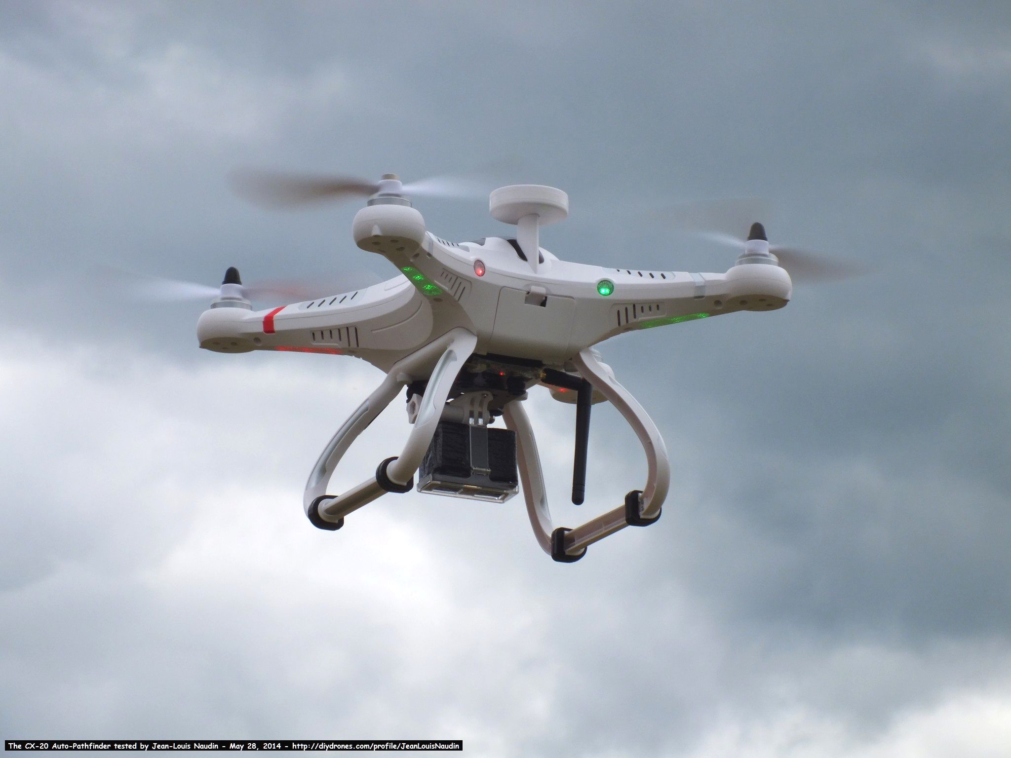
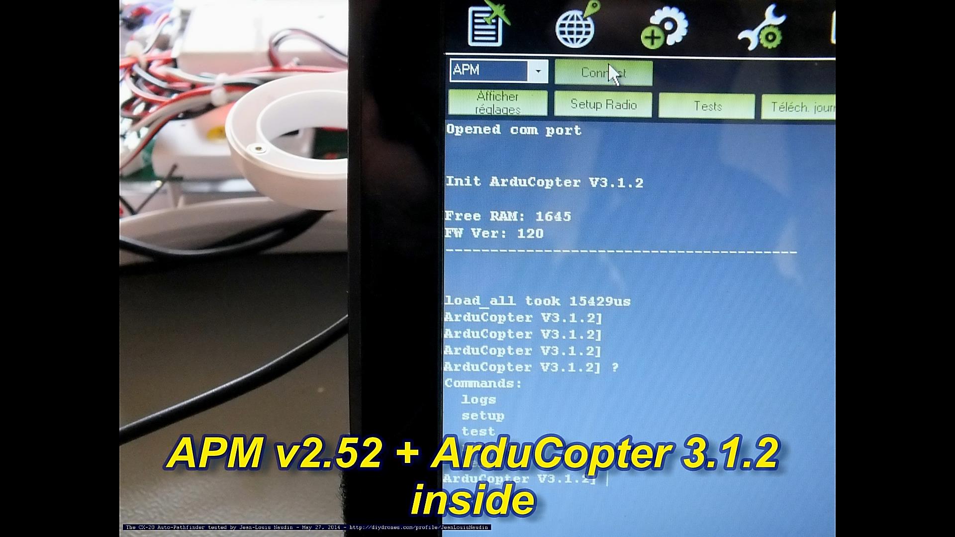
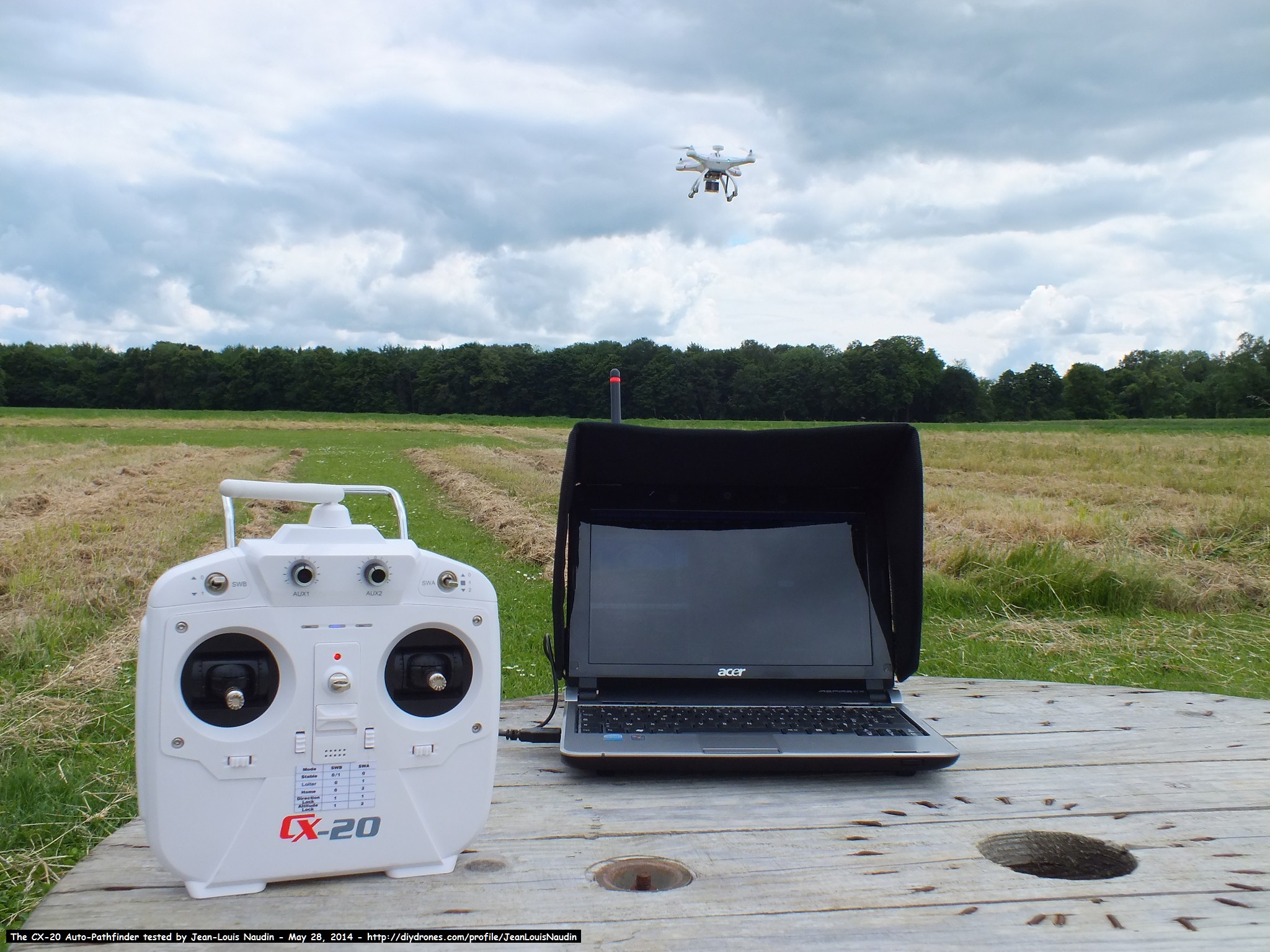
I have successfully tested the Cheerson CX-20 Auto-Pathfinder (also called the Quanum NOVA). This quadcopter uses an APM v2.52 with the ArduCopter v3.1.2 already installed. It fly very well and all the Arducopter features are working very well....

Above, a video during the maiden flight of the CX-20 has been taken with a  GoPro 3 "Black Edition" mounted on the anti-jello mounting base.

Test conditions: Wind 22 Km/h gusting 33 Km/h 

The APM 2.5.2 (with an external magnetometer) with the Arducopter v3.1.2 handle very well the CX-20, the flight is very stable in loiter mode in spite of the strong gusts.

CX20jln02.jpg?width=720

CX20jln05.jpg?width=720

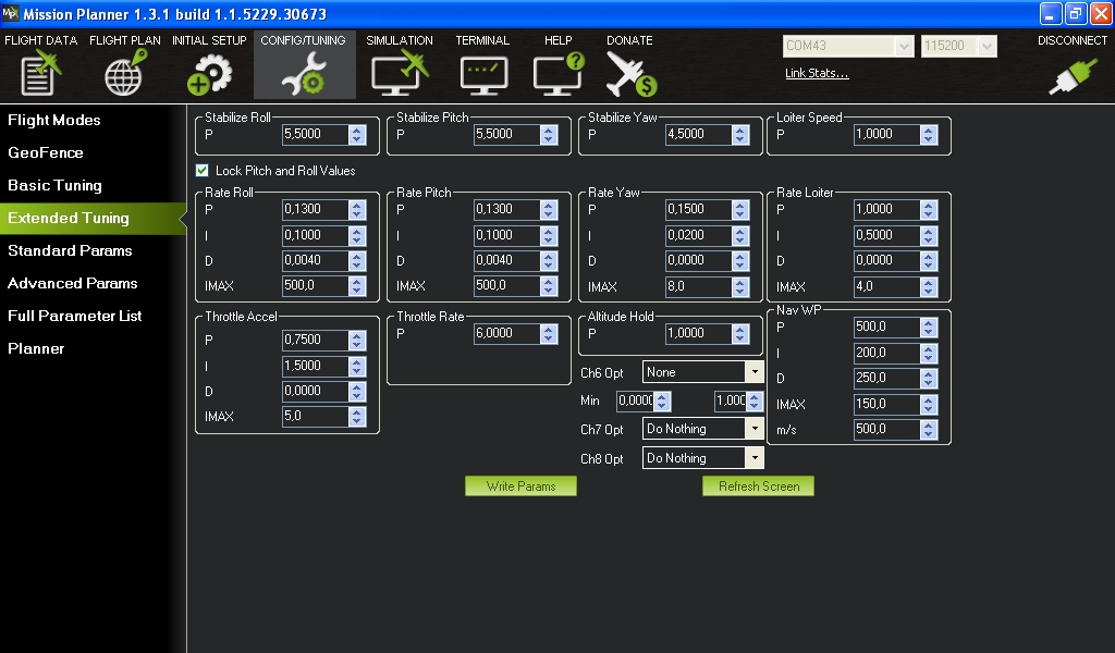
Below the factory PID installed:

CX20jln06.jpg?width=720

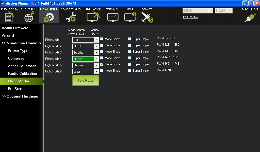
The flight modes set by default:

CX20jln07.jpg?width=720

I have added a telemetry datalink and tested sucessfully the Droid Planner v2.0 (Android) and the Mission Planner (PC).

CX20jln15.JPG?width=720

More infos at:

http://diydrones.com/profile/JeanLouisNaudin

https://github.com/jlnaudin/x-VTOLdrone

Stay tuned,

Jean-Louis

Read more…
3D Robotics

3689596951?profile=original

At $299, it seems like a great deal. I want one! (Note the 3DR credit, only slightly misspelled, at the bottom of the listing). From HobbyKing:

Get in the action with the Quanum Nova, the Ready to Fly GPS drone that ticks all the right boxes. Don't let the low price fool you, this machine is capable of more than any other RTF quadcopter on the market today!

Boasting full GPS functionality such as position holding, return to home and even full GPS waypoint flying, this is a professional level multi-rotor aircraft in an easy to use, ready to fly package that anyone can fly. The Quanum Nova was developed with one primary goal in mind - providing our customers with a simple, user friendly drone capable of proffessional level flight performance. This goal has been realized. Now you have the perfect machine for carrying your GoPro or other similar sized action cameras for shooting awesome aerial video!

When it comes to ease of use, the Nova is at the top of the list. Arriving fully tuned and setup, you simply need to install the landing gear and props, charge the battery and fly. It's that easy. For more advanced users or as your skills progress, you can connect the Nova to MAVLink compatible software such as Mission Planner or others, allowing access to a whole host of programming options including selectable flight modes, GPS waypoint functionality, advanced tuning and so much more!

The Nova features a beautifully molded plastic body which not only offers good looks, it provides durability and is extremely light weight. The lower body shell of the Nova integrates bright LED lights, green in the front arms and red in the rear, making orientation easy in both day and night flying. Additionally, there are two large status indicator LEDs at the rear which show the current status, such as GPS signal and battery condition.

Aerial video is where it's at and the Nova is just the model for it. The Nova is directly compatible with our Quanum Q-2D brushless GoPro gimbal, providing direct fit mounting. Simply bolt-on the Q-2D and connect it to the integrated gimbal control plugs on the bottom of the Nova. The on-board connections provide power, tilt and roll functions for the Q-2D gimbal. There is also a very convenient mini USB connection for connecting the Nova to your PC.

Once you've compared the features, functionality and flight performance of all the Ready to Fly quadcopters on the market today, you will see that a clear winner has emerged...the Quanum Nova.

Features:
• Ready to Fly w/out battery - Just add your choice of battery and charger!
• Multiple preset flight modes such as Manual, Stable (loiter), Direction Locked (simple), Altitude Hold and Return to Home
• MAVLink compatible allowing for GPS waypoint mission flying, advanced tuning and so much more (for Advanced users)
• Precision GPS, compass and altitude sensors
• High quality 2.4GHz 7CH transmitter included (Mode 2)
• Q-2D brushless camera gimbal ready (sold separately)
• On-board tilt/roll control and power connections for use with optional brushless camera gimbal
• Low voltage battery protection initiates blinking LEDs and audible buzzer when flight battery is low
• Easy to see LEDs provide excellent visibility in both day or night flying

Specs:
Main Rotor Diameter: 365mm
Main Rotor Blade Length: 205mm
Main Motor Size: 2212
Length: 300mm
Weight: 300mm
Height: 200mm
Flying weight: 875g
Approximate Flight Time: 15 minutes
Battery: 3S 2200~2700mAh LiPoly (required)
Number of Channels: 7 channels
Rotor Type: QuadCopter
Completion Level: RTF w/out battery (Need to add your choice of battery and charger)

Included:
Quanum Nova GPS QuadCopter
2.4GHz 7 channel radio transmitter (Mode 2 version - left stick throttle)
GoPro Hero 3 vibration dampened camera mount
8 inch propellers x 4

Required:
3S 2200~2700mAh LiPoly battery (must not exceed 105(L)x27(H)x40(W)mm)
LiPoly battery charger
4 x AA batteries for radio transmitter


*Note: The Quanum Nova flight controller  is based on the open source APM Project from 3DR Robotics, the design files per the creative commons license are available under the files tab below.

Read more…
3D Robotics

Autodesk 3DRV at 3DR

3689596927?profile=originalOur worlds (and brands) collide! Stay tuned for news of a cool collaboration.  As the APM/Pixhawk platform extends "from the iron to the cloud", you'll see a lot more third-party software integration in everything from mapping to filming. 

Read more…
100KM

Aerial video with DJI F550

https://www.youtube.com/watch?v=b8I-VsKjkDQ

During our recent mapping mission for S.A.F.E. project near Tawau, I brought along my DJI F550 equip with a Gopro Hero 3 black edition and Tarot T2D brushless gimbal to take a aerial video of their current site building and the propose new.

Video was taken in a sunny morning with very little winds. We are flying in GPS mode and try to be as smooth as possible, but I think we should have been more careful with rudder input. My flight controller is DJI Naja M V2, using the stock motor and 8 x 4.5 stock propeller, the default parameter recommended by DJI work well. I do not need to tune anything to get a good solid flight. 

To me, my DJI F550 is just plug and play without any issue encounter. It is a good plate form to start learning and as I grow in confident I will try the Pixhalk controller. After all, it seems now the ArduCopter code is quite stable and offer a lot more function than a DJI. 

I just start learning some basic video editing with Movie Maker and hope you'll enjoy it. 

Read more…

3689596814?profile=original3689596835?profile=original

3689596954?profile=original

Falcon Unmanned is proud to have provided support to the Mesa County Sheriff's Office (MCSO) in response to a large landslide which hit the county on Sunday night.  After hearing about the event on Monday morning we loaded up a few aircraft and headed out arriving Monday afternoon.  We flew one mapping mission with our fixed wing Falcon over the lower third of the landslide which is the best estimated location of three missing persons in the area when the slide hit.  We launched and parachute recovered from a narrow path about 8 feet wide with tall scrub oak on either side of us.  After returning to the hotel we were able to process over 750 images using Photoscan in a few hours.  The processed data included updated maps with the slide, an elevation model of the slide area covered, google earth overlays, and of course the raw images.  The size of the slide is just mind boggling and still hard for me to comprehend.  It was 2.8 miles long, 1/2 mile wide at the widest point, and on the lower third of the slide our elevation model revealed about 20-30 feet of new elevation gain with some spots over 100 feet deep.  We flew a second flight with Falcon Hover to capture some HD video to hopefully put things in perspective.  When we are clear to do so we'll do another post providing the Google Earth overlay.  As always we are proud to support the Mesa County Sheriff's Office!

Chris Miser

www.falconunmanned.com

info@falconunmanned.com 

Read more…

Introducing the Lynx

3689596971?profile=original

Greetings all. I'd like to introduce Lynx, a fixed-wing sUAS developed by Swift Radioplanes. 

Description

Lynx is a small UAS inspired by military systems because of their extreme durability and practicality (not price). Swappable payloads make Lynx a great choice for photomapping or research. The aircraft is easily launched by hand and can land conventionally or vertically with a deep-stall. The takeoff and landing method – along with its rugged construction – make the system runway independent and ideal for rough terrain or confined areas. Lynx autonomously navigates itself through fight plans or loiter points. Plans can be pre-programmed before takeoff or uploaded during flight. Manual control is possible with the use of a handheld controller. The entire system packs down into two transport cases.

Lynx is not a mass produced product or a modified RC airplane. It is a handcrafted system and built from top quality materials. Each aircraft is flight tested before completion.

Technical

  • Propulsion: electric
  • Construction: Kevlar, carbon fiber, foam
  • Endurance: 90 min w/ mapping payload (demonstrated @ 5174 ft MSL)
  • Cruise: 35 knots
  • Wind Limit: 15 knots continuous – gusting 25
  • Autopilot: APM 2.6
  • Wing Span: 8.25′
  • Weight: 10 lbs
  • Takeoff: auto or manual hand-launch
  • Landing: auto or manual belly land, manual deep-stall
  • Payload Bay: 8.25″ x 4″ x 4.75″
  • Payload Weight: up to 2 lbs
  • Battery Bay: 4.75″ x 4″ x 3″
  • Autopilot Bay: 6″ x 2.5″ x 2.5″

3689596908?profile=original

Features

A quick look at the Lynx: 

  • Tool-less assembly
  • Hand launched
  • Vertical landing
  • Waypoint navigation & mapping
  • Return home failsafe
  • Manual control override
  • Throttle safety key
  • Swappable payloads
  • 90 minute endurance
  • Rugged construction
  • Transport Cases
  • Zero maintenance
  • Quiet, electric propulsion
  • Spare parts included

3689597007?profile=original

Options

Mapping: A professional, ready-to-fly Lynx with integrated autopilot and a dedicated mapping payload backed by Swift RP’s imagery processing and hosting.

R & D: An autopilot agnostic research platform with plenty of room for systems integration and testing. Take advantage of Lynx’s large payload space and removable autopilot tray. Perfect for researchers, academics, hobbyists, and student competition teams.

3689596995?profile=original

Landing

Lynx can belly land or deep-stall. A deep-stall is an extremely steep, yet stable landing method used when operating from confined areas. The deep-stall is activated by a safety switch on the transmitter. The descent can be hands-off or the operator can continue to steer Lynx for pinpoint landings. Unlike a parachute, higher winds are preferred because they steepen and slow down the approach. Also, no extra gear is needed, no parachute folding, no parachute malfunctions, no wind drift, and the deep-stall can be aborted during its descent. The aircraft is designed to break apart upon impact to minimize damage.

Video

https://www.youtube.com/watch?v=eKQKAIjP5z0

Visit www.swiftradioplanes.com for more info.

Read more…
3D Robotics

3689596877?profile=originalI was watching one of my sons play the Arma 3 videogame and was struck by how similar the simulated drone mission planning interface is to what we do with real drones in Mission Planner/APM Planner.  In the game, you can program the drones to conduct autonomous missions, with waypoints and functions such as Loiter at each waypoint. It's great training for the real thing!

If you click on one of the waypoints in the screen above, you get the following options, including altitude.

3689596784?profile=original

Read more…

Proof of Concept Octacopter

3689596766?profile=original

This is a "Prototype" octacopter for my actual plan of octa.

Frame: 1250mm
Motors: 5010 360kv
props: 16" CF
APM : 2.6 with Arducopter 3.1.3 Firmware.


Frame is 1250mm Carbon fiber and it can not fit props more than 15" as a plain octo. and for my "Actual Plan" I don't want to make an X8, because as I read many thread, X8 has 30% less efficiency than a plain octa. My idea is to make an octa with 20" props , but for this size of props, required frame size could be too big to carry around. So, this prototype is like a "proof of concept".


I had 360kv motors for a long time, so i tried a new Prop layout to make 17" props fit on 1250mm frame and they are about 1 inch overlapping each other.
I inverted all CCW motors down and accordingly mounted props.
and left all CW motors on top and mounted props as usual.

3689596730?profile=original

3689596693?profile=original

I Just did initial setup and Without any PID tuning of APM2.6, it flies very well on default PIDs.

Question is : Is this setup/layout is less efficient or more efficient ?
Is it reliable ?

My actual plan is to build a copter that equals SteadiDrone QU4D X in performance.
for that I have following items in hand.
1- KDE Direct XF4014-380kv Motors
2- 18" and 20" High efficiency CF props.
3- Hobbywing Platinum 40A ESCs

              OR

4- T-Motors 40A ESCs T40A
5-I have many frames that could be used , or DIYing a frame isnt a matter.

For my Dream copter, that could be and octa or X8 or a simple quadcopter, I think this list is good to go.
As Gary McCray wrote in "Advanced MultiCopter Design" that :
"It is feasible to produce a QuadCopter that will approach the performance of the $15,000.00 Steadidrone at a fraction of the cost."
Suggestions are appriciated.

Read more…
Moderator

3689596441?profile=original


At Google Community Group for manage the beta testing of VR Pad Station continue to join new members  this is the link : 

http://plus.google.com/communities/102697330643558260161

This is the official Virtual Robotix Discussion group about VR PAD Station 2.0.3 :

http://www.virtualrobotix.com/group/vr-pad-station-2-0

3689596642?profile=original

Today we  uploaded the last revision of  VR PAD Station 2.0.3 . We integrated the mavlink 1.0 telemetry function with original Virtual RC project so now is possible to use VR PAD Station as tools for :

  • Receive telemetry from drone.
  • Setting Parameter .
  • Change Flight Mode.
  • Set waypoint.
  • Send direct command as Return to Landing point , takeoff , auto landing  or Guided mode.
  • Virtual Remote control with a lot of advanced feature for setup the radio stick . (use virtual stick only with in simulation mode it's a beta for evaluation) 

In the new revision 2.0.3 is available

  • A new info bar with a lot of usefull information battery level , gps status , active mode .
  • A new follow me standard mode .
  • Only one connection for different application.
  • Parameter setup for gimbal.
  • New configuration option pannel .
  • New advanced user interface compatible not only with PAD but also with Smartphone android device.
  • A early revision of VR Glass Station a special revision that work on Google Glass device.

We are work in progress with some advanced features as Special follow me mode , Fligh log book and VR Gimbal integration.

The App is compatible with APM Copter , Plane and Rover.

Inside the community could be possible discuss directly with developer about the new request feature .

After join the community could be possible download the APK in a special section of  google play

This is the direct link to google play store beta registration: 

https://play.google.com/apps/testing/com.laser.VrPadStation

.

Feedback about our application are welcome ... :) In the next week we intend improve a lot the application with new feature under development.

Best

Roberto

Read more…
3D Robotics

3689596713?profile=original

3D printing company iMaterialize announces the winners of its 3D-printed drone contest:

We’re thrilled to unveil the 3D printed models of the three winners: Biohazard Tracker by Pascal Breton, APHID by Brian Hamilton and Octobot by Tom Willekens. The 3D printed drones are ready to fly high in the sky!

Biohazard Tracker by Pascal Breton
Pascal’s drone depicting the internationally-recognized biohazard symbol was designed on Autodesk’s Maya software with a noble mission: to access disaster-affected areas and assist with humanitarian aid. Many places that need developmental aid are not easily accessible because the infrastructure was destroyed in a disaster or it simply does not exist. As people are beginning to using drones for development aid, Biohazard Tracker’s goal is to open up new possibilities of 3D printing with a humanitarian purpose.

Biohazard Tracker by Pascal Breton

Biohazard Tracker by Pascal Breton

APHID (Aerially Propelled Hexagonal Isotropic Drone) by Brian Hamilton

Brian surprised us with his mind-blowing Arthropoda slot car design, and now he’s back with Aerially Propelled Hexagonal Isotropic Drone (APHID). This hexagonal drone with bone-like frames gives an impression as if it was an unknown creature from another planet.

APHID by Brian Hamilton

APHID by Brian Hamilton

Octobot by Tom Willekens

Tom Wilekens, designer of this original drone said, “I thought it would be fun to see a sea creature flying in your living room.” And yes, Octobot is a flying octopus! It has 6 tentacle arms holding “bombs” which function as the sockets for the drone rotors. The cables can run through the cable guides build into the tentacles.

Octobot by Tom Willekens

Octobot by Tom Willekens

With more than 30 drone models submitted, picking only three winners was quite tough. We’d like to thank all of the contestants who joined this challenge. And don’t forget that you can 3D print your drone with a 10% discount! We will soon send you a promotion code via email. If you wish to purchase a Flexbot Hexacopter too, you can get more information on here.

The prize package for the three winners are a Flexbot Hexacopter, Autodesk premium membership and, of course, the 3D printed model of each drone. Congratulations once again Pascal, Brian and Tom! Download an app to control your Flexbot Hexacopter here, and enjoy flying your very own drone.

Read more…

3689596620?profile=original

These are the "drones" she is looking for. Peace drones flew during her live performance of DBT at Sasquatch Festival 2014. Multi rotors are becoming more and more accepted with each event that include: a metropolitan video shoot and a live television appearance. Here's one of the reviews from the nights events: (photo credit: Josh Bis)

M.I.A.'s Brings the Noize (Sorta), Also the Drones

Read more…
Developer

APM Planner 2.0.10 release

3689596594?profile=original

[NOTE: There is a problem with autoupdate in APM Planner 2.0.9 (previous) to this release, users needs to manually update to this release from http://ardupilot.com/downloads/?category=35 ]

Some highlights of items new in this release

  • AUTO TUNE support for APM:Plane
  • New Primary Flight Display
  • Google Maps Support fixed
  • Linux Auto Update added
  • TLOG replay (requires a fix :( sorry)
  • Graphing improvements
  • APM:Plane support for channel reversal and Elevons

 see here for http://ardupilot.com/downloads/?category=35 downloads

Read more…
100KM

Primary test with FLIR Tau2 640

https://www.youtube.com/watch?v=xmLRaBxcP6g

Recently I had an opportunity to get my hand on a FLIR Tau 2 640, a 9 Hz refresh rate version with optional 25 mm lens. This is a 10K USD gadget so I am extra careful to handle the test and recheck my gear several time before flight. 

Researcher Kimbery Fornace from London School of Hygiene & Tropical Medicine would like to use this camera to survey the population of marque monkey in her study site. This is parts of her study on Malaria, a disease commonly found in tropical country. Malaria causes symptoms that typically include fever and headache, which in severe cases can progress to coma or death. ( Wikipedia ). So you know she is not flying drone for fun but saving life. She is also the only lady who can fly a drone and successfully map a few area here in Sabah. 

The camera was mounted on an Alware servo base 2 axis gimbal. Power by a BEC which supply 5.2 v to the micro USB port found at the back of the camera. It output composite video which was connect to a digital video recorder and also a wireless video transmitter to give us real time video and OSD. I am using my tested DJI F 550, control by Naza M V2 and data link. With a 4S 6000 battery, all up weight is 2.7 Kg. It can fly for about 8 minutes.

This is the primary test just to make sure when all system are up and running, they will not interfere each other. I also want to confirm it can handle the extra weight. ( I am 200 gram over the recommended maximum weight ). Although I had the gimbal function enable, but the default gain setting seems too slow. I may want to increase it from 20 to 50 gain and see if thing improve.  

I will conduct a few more test before heading to the study site for actual survey mission flight a night. 

3689596384?profile=original

Read more…