All Posts (11086)

Sort by
Moderator

3689596248?profile=original

Dear Friends,

in last month of this year our team work a lot on new electronic boards :

  • VR Micro Brain 5
  • VR Brain 5
  • VR GPS Ublox LEA6.
  • VR Telemetry Module.

Our products have the feature of being based on the original design and not be mere clones, with a research and development team ready to meet the demands and needs of users more evolved.

3689596310?profile=original

VR Brain 5 Micro

The VRBrain Micro is a board of the new 5.x series of extremely small dimensions and is based on the powerful micro processor STM32F4 to 168 MHz , the operating system supports Nuttx as the PX4  and Pixhawk  and It compatible with the APM firmware Copter , Plane and Rover.


The Brain VR Micro is very small and lightweight only 10 grams in weight and 3.7 x 3.7 cm wide. Ideal for setting up of small and micro  sized drones as the frame AV250 .

Supports GPS and magnetometers external standard which it shares with the standard vr brain and allows the controller to provide automatic features as stabilize ,  return to the home , hybrid loiter auto take off and landing .

The board  able to handle up to 12 inputs on sbus receiver and 6  input on  PWM standard receiver , 8 PWM outputs for connecting ESC or Servo .

The source code of the project and ' available on the official repository and DIY Drone and ' ongoing integration of automatic features to APM Planner firmware upload directed, via bootloader.

These are the specifications :

  • CPU STM32F4 VR OS based on NuttX kernel 7.1 
  • 1 I2C EEPROM  for parameter storage. 
  • IMU MPU6000 SPI.
  • MSIC Barometer 10 cm resolution.  
  • 8 PPM Radio RC Input .
  • 8 PWM ESC - SERVO Output.
  • 1 SBUS Radio Input compatible with Futaba SBUS and Spektrum ,too
  • 1 SBUS Servo Output.
  • SD Card Reader until 64 Gbyte.
  • 1 RGB LED 
  • 2 LED Output 
  • 1 Buzzer Output 
  • On board telemetry module availabe at 433 / 868 mhz. (option) 
  • connector for external 3DR/VR GPS + MAGNETOMETER
  • dimension : 3.7 x 3.7  hole 3.2 x 3.2 .
  • weight : 10 gr

Status : First Fly done all work fine available for Pre Order.

VRBrain 5

3689571223?profile=original

3689596331?profile=original

The VRBrain  5 is  the evolution of the 4th revision board, at an architectural level remains very similar to the previous version of Flight Control Board having demonstrated excellent reliability and robustness.

The card features the latest generation processor STM32F4 OS 7.1 Nuttx This card was created with the aim to implement greater redundancy than the earlier and allow the autopilot to integrate into a  distributed wifi network environment .

The board allows you to support 2 IMU sensor based on MPU6000 chip , up to 3 magnetometers and two GPS . In addition to the bus for redundancy and imu ' present an additional bus that allows you to add devices bluetooth or wifi network to interconnect directly to the drone PAD and Smartphone , or to the standards network infrastructure  .
It 's  also available  CAN bus for high-speed interconnection of optional devices.
The board revision 5 have a slot for  use  SD card that allows you to save the  flight logs and make them available online for integration with portals log flight management .

The card bootloader  allows the card to be updated directly from mission planner or compatible CGS applications.

These are the basic specs :

  • CPU STM32F4 VR OS based on NuttX kernel 7.1 
  • 1 I2C EEPROM  e FRAM for parameter storage. 
  • 2 IMU MPU6000 SPI , second imu option.
  • MSIC Barometer 10 cm resolution .
  • 1 MSIC Barometer  option 2th barometer on external  imu. 
  • 8 PPM Radio RC Input .
  • 8 PWM ESC - SERVO Output.
  • 1 SBUS Radio Input compatible with Futaba SBUS and Spektrum ,too
  • 1 SBUS Servo Output.
  • SD Card Reader until 64 Gbyte.
  • 1 RGB LED 
  • 2 LED Output 
  • 1 Buzzer Output
  • CAN BUS for interconnect option module 
  • 1 connector for  VR telemetry module availabe at 433 / 868 mhz. (option) 
  • 2 connector for external 3DR/VR GPS + MAGNETOMETER (option)
  • weight : 23 gr
  • enclosure available.

 Status : pre flight check done , all is good , in production .

Available in pre order . 

VR GPS 

3689584979?profile=original


VR GPS Ublox Lea 6H with HMC5983 Magnetometer


First Virtualrobotix GPS engine using Ublox LEA-6H receiver.

This is a 50-channel high sensitive engine that boasts a Time-To-First-Fix (TTFF) of less than 1 second.

Also provide a rechargeable backup battery to improve warm start.

The dedicated acquisition engine, with over 2 million correlators, is capable of massive parallel time/frequency space searches, enabling it to find satellites instantly.

Innovative design and technology suppresses interference sources and mitigates multipath effects, giving LEA-6H GPS receivers excellent navigation performance even in the most challenging environments.

Virtualrobotix GPS uses an high efficient low noise amplifier to improve antenna signal (19dB) and a SAW filter to select GPS frequencies (see graph below).

3689584848?profile=original

It also mounting an ultimate 3-axis digital compass, with selectable interface SPI or I2C (HMC5983).

This one is an high speed (220Hz output) and high resolution (2 milli-gauss) magnetometer.


Features and Specifications:

  • ublox LEA-6H module

  • 3,3V or 5V Inputs, with low noise 3.3V regulator.

  • 5 Hz update rate

  • Rechargeable 3V lithium backup battery for high efficient warm start

  • Panasonic Low Noise Amplifier for antenna signal with high gain (19dB)

  • EPCOS SAW high quality low-loss RF filter for GPS application

  • 25 x 25 x 4 mm ceramic patch antenna

  • Dedicated I2C EEPROM for receiver configuration storage

  • High resolution compass (2 milli-gauss) and high speed (2 milli-gauss)

  • Power and fix indicator LEDs

  • ArduPilot Mega compatible 6-pin JST connector

  • Exposed pads for simple soldering connection.

  • I2c / SPI HMC5983 magnetometer .
  • 2 ttl tx-rx ser connection.
  • 38 x 38 x 8.5 mm total size, 18 grams.

Status : all it's ok a lot of flight without problem , in production , ready  for pre order. 

Some example from log collected in first test VRX GPS is red Line 3DR is blu

3689585019?profile=original

VR Link (telemetry Module) - micro - standard - advanced OSD - base station .

3689596289?profile=original

3689596402?profile=original

In addition to the autopilot systems in our laboratories have been developing a telemetry system simple , modular and advanced compared to what's available on the market and compatible with the 1.0 mavlink protocol. 

We chose to mantain compatibility with the modules 3DR , but we have worked to expand its functionality.

Micro version :

The micro version it's an add on to the micro brain that allows you to add easily and efficiently support wireless connectivity directly onboard .
The module ' based on the micro SILAB 1000 and it' core normally available .

Standard version:
The standard version is a standard kit with a radio that will allow the connection from the drone to the ground, the main peculiarity of the standard version is that can work independently by simply feeding it through a usb battery pack or a small lipo .
On the ground the module replicates the light and sound of the buzzer's drone.
This feature allows you to detect any alarm signal even if the light on the drone is not ' perfectly visible.

The module on board the drone has available an RGB LED and a speaker very powerful signal that allows you to see and hear even at a considerable distance of the drone .
These new modules using the communication protocol mavlink and therefore are compatible with any drone supports this protocol : VRBrain 4.x and 5.x - APM 2.x, PX4 , Pixhawk , Autoquad etc.

With this feature easily solve a problem that often prevents you from realizing anomalies on board the aircraft such as the loss of the GPS signal , the abrupt decrease in battery level or the sudden lack of the radio signal that activates the failsafe .

Osd advanced version :

On board of drone  can integrate the function  osd simply adding a module dedicated on  the telemetry module . This configuration allows you to add the image coming from the analog video  FPV  camera as overlay of standard fly information as :
artificial horizon, altitude , distance from home , flight mode , battery level , etc. etc..

Status : hardware ok , working progress on first revision of firmware for standard and advanced revision.

We are ready for the worldwide market if you need more info on price ,  pre order , or you want to became a member of our distributor , support and developer team contact : info@virtualrobotix.com 

original blog post : 

http://www.virtualrobotix.com/profiles/blogs/virtualrobotix-electronic-boards-roadmap-prossime-uscite-dei-nuov

Best

Roberto 

Read more…

I just can't seem to kill my APM 2.5!!

She has been with me to over 100K feet on a weather balloon. Completely submerged in water after a ditch crash, and countless crashes that have destroyed frames and other components. I thought for sure, after my fire, she was dead. Almost threw it away. But.... Well.... not yet! Time to strap it on another aircraft. Just need to get some more of the plastic plug connectors that slide onto the pins.
*Edit* I say plane in the video, I meant quad.

I love this thing!!! Best 200 bucks I ever spent. Thanks 3DR!!

http://youtu.be/UTjoM5tiin0

Read more…
3D Robotics

I was fortunate enough to participate in Ideo.org's session in SF a few months ago on drones from public health. The above video was something that they made beforehand, to get the ideas flowing. FastCompanyreports:

Some of the ideas they suggest in this video, like delivering medicine in places that are hard to reach by roads, have already been tested in some areas and may be close to becoming reality. Others, like real-time imaging, have been used by industries like mining and agriculture, and could easily be adapted to serve the greater good. In a disaster, a glider could quickly fly over impassable roads, making a map with photos of survivors.

In remote areas, a drone floating high in the air could improve connections to the outside world, so a village nurse could talk to doctors at a distant hospital. Local entrepreneurs might begin to rent out drones to do everything from delivering goods to testing water and monitoring crops.

“In the next year or two, we’ll see a handful of exciting small-scale drone programs, like post-disaster health communications and on-demand vaccine delivery,” says Danny Alexander, a senior designer for Ideo.org. “The technology--and the regulations that govern them--need a lot more development, though, so we won't be seeing their full potential until closer to 2020.”

The possibilities go far beyond health care--some organizations are already using drones to help protect wildlife, and others have suggested using drones for everything fromprotecting cyclists to harvesting crops.

As more drones are used to help people, their image may slowly begin to change.

"Drones look like agents of war and behave like pesky insects--they're in desperate need of design," Alexander says. "By reconsidering the way they look and interact with people we'll be able to alleviate some fear, but the big shift in perception will come when drones are more broadly used for good."

Read more…
3D Robotics

3689596196?profile=original

From Gizmag:

Although hippos may look slow and docile, they're actually very aggressive, killing more people every year than any other large African animal. So, it would follow that you wouldn't want to swim anywhere near them. That's why when researchers from Yale University and the Cary Institute of Ecosystem Studies wanted to study the effects of hippo dung on water quality in Kenya's Mara River, they sent in three autonomous air boats instead of people. To help those boats blend in, they were dressed up as crocodiles.

There are an estimated 4,000 hippopotami living in the Mara, each one depositing about 22 lb (10 kg) of feces in the river every day. When flow rates are high, that dung is simply flushed downstream and dispersed. At lower flow rates, however, it sits on the bottom and is fed on by bacteria, which also consume much of the water's oxygen content.

When flow rates rise again, oxygen levels downstream from the hippo pools can also suddenly drop, sometimes resulting in massive fish die-offs. Although it's suspected that this is due to the decaying dung being carried to those areas, the theory has never been confirmed. That's where the Lutra airboats came in.

An undisguised Lutra airboat

Manufactured by Carnegie Mellon University spin-off company Platypus, the vacuum-formed plastic boats are two feet long (0.6 m) and weigh 13 lb (6 kg). Equipped with Android smartphone processors, they're able to navigate waterways autonomously while using onboard sensors to analyze water properties such as temperature, oxygen content and electrical conductivity. They also have sonar sensors, which they used to create depth maps of the pools, and to document the location and depth of hippo feces.

In order to minimize the chances of the animals attacking the boats, a local Maasai guide suggested that they be disguised as crocodiles. The approach seemed to work for the most part, with the exception of one occasion on which a hippo unsuccessfully attempted to chase down one of the watercraft. You can watch it in the video below.

Although the researchers are still analyzing the data, they're hopeful that the study will provide valuable insights on the role that hippos play in the water quality of the river.

Sources: Carnegie Mellon University, Platypus

Read more…
MR60

3689596053?profile=originalHi,

After my Talon build part 1 & 2 (here), you'll find herefater my first experiments with the installation of Pixhawk and other components in a fixed wing UAV. What's great with this Xuav Talon model is its huge internal bay. So I started to draw on paper the location of all of the components of my setup, as shown in top picture.

I imposed to myself some rules/principles:

-to keep different antennas and receiver as far apart as possible.

-not to use of the wings to install any components. This is a compromise to keep transport/assembly/unassembly easy (wings can be removed with two screws).

-contrarily to certain builds, keep the gps with a clear sky view (eventhough it would probably still work buried in foam)

-have backup power on pixhawk: 3DR power module + SBEC on RC rail (+ required to power servos)

-to plan wiring before installing components; to draw a wiring scheme as shown above. This to avoid bad/wrong connections and ground loops. On the latter principle, Pixhawk has a weak point : if you power , as a backup, via a SBEC the output rail, not only do you have to mess with the installation of a 5.6V zener diode to protect the board, but you are forced to connect the ground wire too (creating a ground loop with the ground coming from the power module). This should be adressed in a next card's version : integrate the zener diode in the PCB and make it right like APM was: a common shared ground for all circuits of the FC.

Let's see what was done,

1. Customized electronics platform to host Pixhawk:

I don't know what these foamy airplane manufacturers think about when they design their model : they always forget to plan for a leveled horizontal surface, inside the bay, to host the flight controller board (maybe they are old school and never use a FC ?).

As a consequence comes a first question: where to place the pixhawk board so that it is firmly held in place (with room to use an anti-vibe platfrom underneath) , at the center of gravity and perfectly horizontal when the plane is horizontal ?

My answer is to add a diy custom plywood plate held horizontally in between the two existing plywood pieces that are used to reinforce the wing attachment points on the fuselage:

3689596074?profile=originalSide view of the added black painted plate:

3689596038?profile=originalAs can be seen on this last picture, Pixhawk sits on the custom platform. It leaves a big gap underneath which is useful to pass cables and/or position other components on the bottom below the platform. It gives also the advantage to move pixhawk far away enough from possible electromagnetic interferences of cables/electronic components that would be positionned underneath, on the bottom of the bay.

2. RC receiver and antenna's positionning:

I decided to start with a FrSky 2.4Ghz rc control (a long range opensource Hawkeye DTF UHF alternative is ready and tested but will wait for now).

3689595939?profile=original

I use a X8R FrSky receiver with the PCB antennas. It is supposed to give a 20% range increase versus the simple coax wire antenna's. To be efficient they have to be placed perpendicular to each other (to cover horizontal and vertical polarisation. Especially useful when the plane banks, in order to not loose the signal).

Question : where to place the receiver, pcb antennas and how to have them perpendicular ?

Answer : eat a popsicle; then insert and glue the popsicle stick in the fuselage on the back of the bay. This location is far away from the motor/ESC, far from the telemetry antenna and FPV antenna. One pcb antenna is then velcro'ed vertically on it.

Using a solder iron, I melted a hole through the fuselage to pass the antenna wires. The receiver is velcro'ed on the side of the fuselage as seen on picture.

3689596112?profile=originalThe second antenna is place perpendicular to the first one on the fuselage body.

3. 3DR GPS and compass module installation:

I wanted an external GPS installation. I did not want it on the wing, nor drill a hole in the top foam cover.

Furthermore it needed to be close enough to Pixhawk because of these damned DF13 cables that are delivered way too short in the 3DR kit... (=> request for 3DR, in your next FC version, replace these cables by longer ones and use connectors that DIYers can modify easily)

3689596160?profile=original

The GPS + compass module is installed on the back of the bay where the air inlet (cooling the motor) is located. It provides a small horizontal surface that is perfect for the GPS to sit on. However a "cable pass-through" hole has to be melted through the foam, to reach to Pixhawk (again a fined tip solder iron makes the job).

4. Telemetry module installation

3689596129?profile=original

Current 3DR telemetry modules are delivered in a plastic casing that makes it easy to velcro to a supporting surface.

I decided to locate the module in the front of the bay where this telemetry casing fits perfectly on the internal side of the fuselage.

An iron solder was again needed to melt an antenna hole.

3689596097?profile=original

5. Airspeed sensor (Pitot tube) installation:

The airspeed sensor consists in a pitot tube that ideally should be installed on the front (nose) of the plane. However that will be reserved for the installation of the FPV equipment. Also, the sensor's silicon tubes and I2C wires are too short to go all the way from the nose to pixhawk.

So i chose an alternative installation on the side of the fuselage,

3689596219?profile=original3689596181?profile=originalI found an easy way to attach the pitot tube to the fuselage so it is maintained fixed and horizontally about 1,5 inch away from the fuselage. A zip tie is used around the metallic tube. The "plastic tail" of the zip tie is glued with CA on a CF rod. Hot glue is used to reinforce and fix the rod perpendicular to the tube.

The cf rod is pushed through the foam on the side and hot glue on both sides seal the rod firmly.

When travelling, the metallic tube of the sensor can be slided out of the zip tie.

6. Side note on servo control horn and control rod installation:

It is said by xuav talon experts on rcgroups forum that the maximum deflection of control surfaces should not exceed 20 degrees. Indeed only very small surface movements are required to fly the Talon (and people tend to move their sticks too much).

So I decided to mechanically limit the surface's deflections by positionning the control rod attachment point outward on the control horn. That way surface's movements are limited to about 20 degrees.

The consequence of this is I do not get perfect 90 degrees angles between horns and the control rod. I hope this will not create more adverse effects than not limiting the amplitude of the surface's deflection...

3689596258?profile=original

This ends part 3 of the XUAV Talon build.

Soon to follow : FPV components installation.

Cheers,

Hugues

Read more…

Nature inspiring drone development

3689596013?profile=original

BBC News has published a brief survey article about research being done in 14 universities (some of which are listed here). The article includes links to several videos of ongoing research.

"In the journal Bioinspiration and Biomimetics, 14 research teams reveal their latest experimental drones.

They include a robot with bird-like grasping appendages, and some that form a robo-swarm or flock.

The developments are inspired by birds, bats, insects and even flying snakes."

The image above is from the last video in the article, about small rovers with ant-like behavior.

The full article can be read here.

Read more…

Drone_Nest7.jpg?width=500

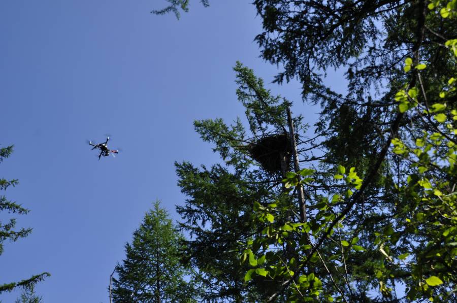
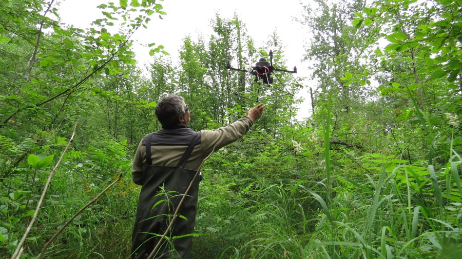
In the past 2 years we have been monitoring the Steller's Sea Eagles nests in remote regions of Siberia. Arducopter and Naza-based foldable quads were used. Be believed that this was the first (2012) successful deployment of the UAV for conservation of eagles in the world, which lead to a publication.

Usage of quads demonstrated a significant decrease of disturbance during nest surveys. Total time needed went down from 40-60 mins (climbing) to 3-4 mins (UAV flight in canopies). Flights were performed with the spotter and FPV equipment.

We have published a paper on the practicalities of usage of the quads in remote regions (no electricity, no roads, no computers) here (bilingual):

http://docs.sibecocenter.ru/programs/raptors/RC27/RC27_253-260_Potapov2.pdf

UT__0777.jpg

The activity was publicized on the Russian National TV (Sorry, Russian only)
or

Currently the Magadan State Nature Reserve is going to purchase long-distance fixed wing UAV to monitor bears and ungulates. Huge contrast to the USA ban on drones in National Parks.

Read more…


3689584418?profile=originalJeff asked about adding a 'Balun' to a simple dipole, so I thought to disertate a little once more on the subject...

The purpose of a Balun is to allow the connection of a coaxial feed line ( unbalanced feedline) to a balanced antenna , such as a dipole.

Picture at left is a Circularly polarised turnstile antenna. Although this is for 75ohm coax, similar strusture are possible for 50ohm as well. Significant in this particular design is the fact that the 75ohm phasing cable section serves the function of the Balun as well. 

What we are trying to achieve with a Balun, or its electrical equivalent, is to prevent common mode currents from flowing down the coax feedline. These currents are induced when a dipole is simply connected directly to a coax feedline, one element to the inner conductor, and one to the outer. The currents flowing in the dipole elements result in the electromagnetic wave being generated and radiated by the dipole elements. However, the current flowing in the element connected to the coax outer sleeve has to return to the generator ( the transmitter) and so does this by flowing on the outer sleeve of the coax cable. This current induces radiation from the coax outer sleeve, thereby distorting and destructively interfering with the dipole radiation pattern. This current can also return all the way back to the transmitter, and induced energy flows in adjacent cables and looms - In a small UAV with wiring close to everything, this sometimes manifests as servos twitching in sync with the video or datalink transmissions, etc, among other phenomena. 

3689595929?profile=original

The balun on the left could be used to feed a folded dipole. Such a dipole has a feedpoint impedance of around 300ohms, and this balun exhibits an impedance step-up ratio pf 4:1. SO a 75ohm feedline would result in a good match to the 300ohm dipole, with a unbalanced to balanced trasformation in the deal.

However, there exist a number of alternative 'baluns' that can be used where an impedance transformation is not desired, a sort of 1:1 Balun.

Note that these are not really baluns in the true sense, but actualy perform the same duty by acting as a choke for the RF currents flowing on the coax outer sleeve.

3689595987?profile=originalThe left image is often referred to as the 'Bazooka' Balun. It is a 1/4 wavelength of tubing, snugly fitted over the coax sleeve insulation, with the bottom end of the tube soldered all the way around to the coax sleeve braid. The top end of the tube is open and insulated from the rest of the antenna. This works by the 1/4 wave section forming a short circuit to the flowing currents at the base, and a high impedance at the top, choking of said currents.

The following are variations of the theme:


Where in the Bazooka Balun a tubular sleeve surrounds the Coax, a single 1/4wave length of conductor can be substituted in the following manner.3689595838?profile=original

The Bazooka balun is preferred and is more efficient. 

In order to not distort the antenna radiation patterns ans not cause EMI with other on-board electronics, it is always desirebale to use a Balun type feed for balanced antenna such as dipoles, Turnstiles, etc. The examples shown can be used with 1:1 and 4:1 impedance match for all dipole types.

The Nampilot.

Read more…

3689595872?profile=original

My latest blog looks at the importance of choosing the right drone software platform to support your business.

Just like Google vs. Apple

When the Apple iPad first appeared on the market in 2010, I didn’t jump in to buy one. I didn’t own an iPhone, I had a company-issued Blackberry, so I wasn’t motivated. Besides, I figured there would be a better model a year or so later. So I waited. By the time Apple released the iPad 2 in 2011 all my friends had one. It looked and felt great in the hand. I thought the user interface (UI) was pretty slick. But I also heard about this thing called Android in development by Google and the Open Handset Alliance (OHA) with a similar and perhaps better UI. I was conflicted about which to buy first. I eventually got an Android tablet on the promise of what could be an open source model. However, after one disappointing experience after another, I got rid of it and switched a year later to an iPad first generation. I stayed on that path and haven’t looked back since.

As Diffen says:

Google’s Android and Apple’s iOS are operating systems that provide a good example of open source vs. proprietary. Both are used primarily in mobile technology, such as smartphones and tablets. Android, which is Linux-based and partly open source, is more PC-like than iOS, in that its interface and basic features are generally more customizable from top to bottom. However, iOS’ uniform design elements are sometimes seen as being more user-friendly.


But wait, I thought we were going to discuss drone software. We are.

For all drones, the interaction between the user and the aircraft, and the aircraft and its hardware is mediated by software. As I have written here, the quality of the pilot experience can be driven by the features and the quality of implementation, but the comparison with tablet and smartphones is a good one. Just as with your smartphone and tablet systems, choosing the wrong software platform for your drone can produce some very high switching costs should you decide later you need to change. In this post, I’m going to look beyond manufacturers’ claims and help you understand the differences with the following explanations of what is it, who makes it, who uses it, and what you need to know.

Read more here: http://droneanalyst.com/2014/05/23/which-is-better-open-source-or-proprietary-drone-software/

Read more…

3689595730?profile=original

Not a huge post today, but thought I'd show off the new build. Still got to tune it a bit, but runs pretty tight already. But here are a few simple mods you can make to improve your 2014 quad, that are really easy to do, yet will significantly improve performance. And if you're into aesthetics, it still looks completely standard. Unfortunately, it won't decrease it's surprisingly heavy weight...

1. Use rubber risers for the electronic plate.

Really simple mod has two functions - reduces transfer of vibration, and rises it above the noise a tiny bit more.

3689595900?profile=original

2. Use a 1/4 wavelength antenna.

For us EU 433 users, this will improve your 3DR telemetry range a bit. Remember and bump your tx power to 20, of course.

3. A 4-in-1 ESC

...makes for a cleaner build. But you should solder in a 3DR PM as well - compassmot works better on CURRENT. I'll do that eventually, but I've getting volts/amps etc from the immersion OSD. I should go to minimOSD at some point to save weight, and clean up the back plate a bit.

4. 35mm risers

Allows you to fit an ant-vibe platform, and raises the compass yet further

3689595905?profile=original

5. Anti-vibe plate

The 3D printed version!

I went with tmotors and 12" props (because that's all I had lying around).

..and that's it. Told ya it was a short one...

Read more…

Balloon burst

3689595713?profile=originalWe recently tested a couple of Replay XD cameras on a Low Orbit Helium Assisted Navigator (LOHAN) flight. Pretty good kit, and in the process they captured some spectacular footage of the balloon burst at around 30,000m.

The video's right here. Enjoy.

Read more…
3D Robotics

Drone dance performance

Lovely. Via The Verge:

[This is] from Japanese dance troupe Eleven Play, which turned three small drones into dancers during a recent performance in Tokyo. The drones are paired with three actual dancers and for a while fly smoothly around them, seemingly responding to their movements. By the end of the four-minute routine, however, the dancers vanish, leaving the drones as stars of the show.

Read more…

3689595398?profile=originalHello Diy Drones Universe,

This is Joshua Johnson CEO and Founder of CAD Drones, LLC and CADDrones.com "The Open Source website for CAD and Drones".  We are 19-21 days away from having our Drone Product go LIVE on Kickstarter.com!  Right now CADDrones.com is moving along but without the help and ideas of volunteers in the Drone Industry we don't know which direction we should go moving forward.  Being a volunteer for CAD Drones, LLC and CADDrones.com will give you the opportunity and expirience in shaping our website into what you feel is best for the International Drone Community.  Our website's focus is on CAD, 3D Printing, and Drones and meshing them together under one roof.  We are trying to build an Open Source environment that will benefit the Drone Industry for decades to come!  Once our Kickstarter Campaign is underway we are going full steam ahead with the consulting side of our Drone Tech Company and turning volunteer positions into paid positions.  We are looking for volunteers with various expertise and strengths that believe they have what it takes to help build a Drone Product, Company, and website into a success!  We can't unveil our product to the volunteers or public until we get closer to the Kickstarter Campaign Launch.   Volunteers who we feel share our same passion to advance our website CADDrones.com and also to build a reliable resource for the Drone Industry will more than likely see their volunteer positions transition into paid positions after the launch of our Product on Kickstarter!

What Volunteer Positions We Need Filled:

  • 1 Graphic Designer ( Someone who is willing to help us turn CADDrones.com into a visually appealing website and someone who is interested in using their Graphic Design talents to create information graphic pieces that can be used to educate our website members about various topics )
  • 1 Wikipedia Administrator ( Someone who is good with organizing and structuring research and factual pieces/information from multiple sources under one depository in an organized, useful, and educational manner ) 
  • 1 Lead Moderator ( Someone to build, manage, and organize a small team of volunteer moderators )
  • 3 Moderators ( 3 Moderators besides the Lead Moderator who are willing to work as a team to decide on category names and organize and come up with a structured plan for the Forums, Blogs, Photos, and News Page so its a useful tool for our members )
  • 5 Website Developers ( 5 Web Dev's willing to use their Programming skills to create HTML and code based features for CADDrones.com that will assist and educate the commercial and/or hobby Drone Community )
  • 5 Business Advisors ( 5 people are willing to mentor me by sharing advice and ideas with me to help CAD Drones, LLC grow and prosper )
  • 5 CAD/3D Printing Specialists ( 5 people with skills in CAD and/or 3D Printing who are willing to donate their time by creating blogs, forum posts, and assist our members who are using CAD and 3D Printing to help assist in their drone projects. You will be also be in charge of build up our CAD File Database with useful files for our community )

 (**If you would like to volunteer for a position you feel is needed on CADDrones.com but is not listed below please email me your position idea and how you would fit the role**)

If helping the CAD Drones Community and joining an up and coming Drone Start-up Company as a volunteer and possible future employee is something that interests you please feel free to email a "creative resume" to me at: JoshuaAllenJohnson@Gmail.com or post it on our Volunteer Blog Post.

Read more…

Multiwii v2.3 Working on Arduino DUE

Most of us knows Arduino DUE It is a 32-bit ARM processor SAM3X8E that came with alot of expectation that a new era of Quadcopter firmware will be built on it -at least I thought so :) -.

Well that was very inspiring until I found that the new board has no EEPROM to save configuration settings, and the second problem was the 3.3V that made it incompatible with 5V interface.

Naze32was the first thing that made me have a second thought, as they solved the EEPROM issue by using Flash instead. So I started looking for similar code for Arduino DUE and thanks to Google could I found one written by cmaglie :)

Back to 3.3V. A brave man Rouan had no issues when dealing with 3.3V. I believe this is due to logic high is less than 3.3V even when working with 5V logic, so ESC can work directly now. for RX it seems that the 1-2ms pulse with 50Hz is not enough to burn the ports. This is based on my expectation, so I am not sure of the correct reason here.

Anyway I tried to proceed with Multiwii v2.3 and make the code compilable on both 8-bit AVR & new 32-ARM processor.... yes the same code.

It took be 21 days of dedication for this task, but guess what it is done :)

Although the firmware is flyable but not all configuration has been tested or even converted, I made a mass conversion here, but at least it is a good step forward. 

GitHub is here  

Read more…