This video demonstrates a modified ArduPilot-Gazebo simulation for artificial intelligence (AI). A ROS subscriber is implemented with a AI python script. A human walking actor is added in Gazebo to simulate a human obstacle. More details can be found at my wiki.
All Posts (11069)
Sort by
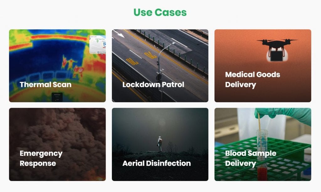 COVID-19 i.e. the coronavirus disease has been aptly called the Black Swan of 2020 — a global contagion that will disrupt public health and the global economy. With social distancing turning out to be insufficient, governments across the world are moving to comprehensive lockdowns, likely for weeks if not months, in order to ‘flatten the curve’ and get this pandemic under control.
Get started with FlytNow Pro for free, to help your employees, customers, partners and the general public tackle COVID-19 safely. Learn more at http://flytnow.com/COVID-19

In these trying times, each company is striving to do its part in helping their employees, partners and customers cope. FlytBase, for our part, is making FlytNow Pro available for free (until at-least May 31, 2020) for customers who seek to deploy drones as an aid to help control the virus.
Safety via Autonomy
The most powerful weapon in the battle against COVID-19 is avoiding human-to-human contact. Drones can thus serve us well — when used remotely and autonomously. Whether monitoring public spaces via live video feeds, delivering medicines to the last mile, or aiding public safety personnel during incident response, autonomous drones can help minimize human interactions while ensuring that food, medicines and help reach people on time.
Monitoring of Public Spaces
Across the world, national and local governments have rapidly started closing public spaces — train & bus terminals, schools, colleges, airports, parks, malls — and soon even commercial offices and retail shops. Unfortunately, there remains a need to monitor and enforce such shutdowns, since not all members of the public are diligently adhering to social distancing and self-quarantines.
Drones, equipped with payloads such as beacons, loudspeakers, and sirens, can thus serve as a public safety aid — sending live video feeds to COVID-19 control centers, warning people of the need to stay indoors, and perhaps even spraying disinfectants! Thermal cameras mounted on drones, and controlled remotely via FlytNow, can automatically identify crowds, which can then be quickly dispersed to minimize human-to-human transmission of the virus. Such low-latency video streams can be shared with stakeholders across geographies to help monitor the overall social situation and make informed decisions about shutdowns, crowd control and public safety.
Food & Medicine Delivery
With health workers directly exposed to the virus, drone service providers can use FlytNow to deliver medicines, first aid kits and other emergency supplies — to homes as well as hospitals. Via 4G connectivity, drones and their payloads can be remotely controlled — such missions can be planned and launched from cloud-based dashboards, accessible to multiple stakeholders. Live video streams in the FlytNow dashboard can help confirm medical deliveries, and the recipients can participate in flight planning and monitoring, in a remote yet secure manner.
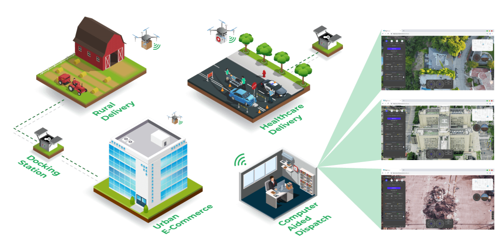
At a time when supply chains are getting disrupted, remote and/or rural populations need to be proactively assisted with daily supplies. Drones are an ideal solution for this urgent need — via EVLOS and BVLOS operations that can be remotely planned, controlled and monitored using FlytNow. Even in urban areas, public health officials are strongly encouraging e-commerce and delivery of daily provisions, instead of people visiting supermarkets, restaurants and pharmacies.
Emergency Response
First responders, whether police, firefighters or health workers, now need to be themselves protected against the virus during incident response. Sending drones before people must become an integral part of such operations — powered by FlytNow capabilities such as fleet management, precision landing, autonomous charging, video recording, dual-camera feeds and airspace compliance.
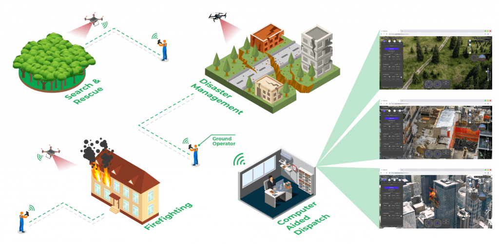
With the pandemic expected to last a while, public safety officials will have to plan for emergency response (with minimal involvement of humans) during floods, hurricanes, and other natural disasters.
FlytBase, Inc. salutes and wishes well, all those involved in this mammoth exercise — our doctors, nurses, aid workers, public servants, first responders, and many other selfless and brave volunteers. We are keen to do our part by leveraging autonomous drone technology to mitigate the adverse effects of the novel coronavirus.
Get started with FlytNow Pro for free, to help your employees, customers, partners and the general public tackle COVID-19 safely. Learn more at http://flytnow.com/COVID-19
Many commercial drone operations rely on several people in the field: usually a pilot, a payload/camera operator and sometimes additional domain experts depending on the mission type. In times of a pandemic - as we have it with Covid-19 at the moment - you want to avoid people being outside or travel as much as possible. But some drone operations can't be postponed - for example inspection of critical infrastructure, Search & Rescue or curfew enforcement. In this situations staff in the field should be reduced as much as possible to protect them and the entire population.
Sky Drone technology allows you to fully remote-operate a drone and its payload over a 4G / 5G cellular network. Even if your payload operator is in home quarantine - productive work for a mission critical project is still possible. He will be able to control the camera and gimbal from hundreds of kilometers away using low latency streaming technology, capture images and inspect them immediately from home.
Using Sky Drone technology we can help you to implement all of the following scenarios, minimizing or eliminating the need to send people to a target operating area.
Scenario 1: Pilot in the field, Payload Operator and Domain Experts operate remotely
The easiest way to get started is to reduce the staff in the field to the drone pilot only.
Both payload/camera operator and other Stakeholders can watch a low latency life stream from anywhere in the world, operate the camera and take still images for instant review.
Scenario 2: Safety pilot in close distance - Drone and payload operated remotely
The next step is to only have a safety pilot that can take over control of the drone in an emergency situation and to comply with relevant Line-of-Sight regulations. Both drone and payload are operated remotely via 4G/5G connection.
Scenario 3: Full remote operation - nobody needs to leave the house
Full Beyond Visual Line of Sight (BVLOS) operation via the 4G/5G network. This depends on local regulations and possible BVLOS licenses in your jurisdiction but allows you to execute your drone mission fully remotely without leaving your house.
Figure 1: (left) Foam drone with optical flow sensor mounted under a wing, Summer 2001. (right) Foam drone with optical flow sensors for attempted obstacle avoidance, Summer 2002.
Today it is universally acknowledged that drones operating close to the ground need some sort of obstacle avoidance. What I am about to tell is the story of our own first attempt at putting obstacle avoidance on a drone, during the years 2001 through 2003, using neuromorphic artificial insect vision hardware. I enjoy telling this story, since the lessons learned run contrary to even current practice but, upon reflection, should be common sense. I learned an important lesson that is still relevant today: The best results are obtained with a systemic approach in which the drone and any obstacle avoidance hardware are holistically co-designed. This contrasts with the popular approach in which obstacle avoidance is a modular component that can be simply added to a drone.
Initial Successes with Altitude Hold
As discussed in my last post, by taking inspiration from the vision systems of insects, we implemented interesting vision-based behaviors on drones using only several hundred pixels. Nineteen years ago, in 2001, we built an optical flow sensor using a 24-pixel neuromorphic vision chip and a modest 8-bit microcontroller. We mounted the sensor on the bottom of one wing of a fixed-wing model airplane to view the ground (Figure 1 left, above). The sensor was programmed to measure front-to-back optical flow and from that estimate the airplane’s height above ground. We implemented a simple proportional control rule that would increase the aircraft’s throttle or elevator pitch as optical flow increased. The system worked quite well- once the aircraft was set to the target height, it would fly for as long as the battery lasted (and wind conditions permitted). The sensor only operated the throttle or elevator- the human operator would still steer the aircraft with the rudder via a standard RC control stick. We verified the ability of the sensor to ascend or descend gentle slopes. We even later achieved similar results over unbroken snow on a cloudy day!
You can see one of the videos here, which I shared previously: https://youtu.be/EkFh_2UX-Jw You’ll hear a tone in the video. Our telemetry was laughably simple- The sensor transmitted this tone by on-off keying an RF module at a rate that varied with optical flow. The camcorder operator carried a scanner (set to AM mode) that received and audibly outputted that tone, allowing it to be recorded with the video of the flight.
I look back fondly at the scrappiness of our approach! I personally designed the vision chip using free and open source tools (Magic and Spice) on a $1000 laptop running Linux. I then had the chip fabricated by the MOSIS service for $1200. Our most expensive piece of lab equipment was a PIC microcontroller emulator that I think cost me about $2500 at the time. I find it interesting that a “fabless semiconductor” startup today “needs” tens of millions of dollars to start, but that is a topic for another post. Going from the design of the vision chip (December 2000) to the first successful flight (July 2001) took eight months, much of it learning how to build and control the model airplane!
Failed Attempts at Obstacle Avoidance
After getting “altitude hold” under control, I decided to next tackle obstacle avoidance, again using optical flow. I drew inspiration from the work of noted biologist (and MacArthur grant winner) Michael Dickinson- His laboratory then recently recorded the 3D flight paths made by fruit flies in a chamber and then analyzed how the flight path turned in response to an obstacle, in this case the wall of the chamber (Figure 2). Not surprisingly, the flies tended to travel in straight lines until they were adequately close to the wall, at which point they would execute a sharp turn away. An analysis of the flight paths and the environment showed that the turn reliably happened whenever the optical flow due to the approaching wall crossed a threshold. The fly would then resume forward flight in the new direction until another part of the wall was reached.
Figure 2: 3D flight paths made by fruit flies in a confined arena. Apologies for the poor image quality.
Back in 2001, this was a behavior that I thought could be implemented with a few optical flow sensors. My first attempt had just two optical flow sensors mounted on the aircraft to view diagonally forward-left and forward-right. The controller was programmed to detect if the optical flow was high on one side, at which time the controller would turn the aircraft’s rudder to steer away for a fixed duration. Here is a video clip of an early test: https://youtu.be/Ao3rhiQR0BM In this case the tone indicated the rudder actuation- a middle pitch indicated neutral e.g. no actuation, while a high or low tone indicated an attempt by the rudder to turn one direction or the other. It was comical- the optical flow sensor picked up the tree and initiated a turn, but not soon enough to avoid a collision!
We spent almost two years trying to improve that demonstration. I designed improved neuromorphic vision chips (with 88 pixels), then we made lighter yet more powerful versions of the optical flow sensors. We even experimented with different optical flow algorithms by varying the firmware on the microcontroller while still using the same vision chip as a front-end. Figure 1, above right, shows one iteration. It had four sensors- one downward to control height and three forward to detect obstacles. We added a proper telemetry downlink that allowed us to record and display data such as optical flow measurements, aircraft yaw rate, and control responses. We still did not achieve improved obstacle avoidance. We did, however, produce a graphical display showing three beautifully hilarious sequential events: First the increased optical flow due to the looming tree, then the control response by the rudder, and finally a sharp spike in the yaw rate as the aircraft slammed into the tree! The only thing that was “improved” was the monetary value of the electronics we had to fish out of a tree after each crash…
Eureka!
It is human nature, when trying to solve a difficult problem, to go down the same general path and bang your head against a dead end until you accept that you are indeed at a dead end and need a different approach. In my case, the epiphany came when I took a second look at the flight paths recorded by Prof. Dickinson. I saw something that I had missed before. Sure, the flies flew a straight line and then made sharp turns upon detecting an obstacle. What I had missed, however, was the sharpness of the turn- the arc flown during the turn had a radius of a few centimeters. More significantly, the turn was made about ten centimeters away from the wall. I imagined a parameter “R”, which might be the “turning radius” of the insect (Figure 3). A “turning radius” is not a native measure of the maneuverability of a flying insect or drone in the same way that it is for a ground vehicle. However, it does serve as a first-order approximation. I then imagined a parameter “D”, which might be the size of an obstacle to avoid or the distance from an obstacle at which the drone or insect would turn to avoid it.
Figure 3: D/R ratio
I then realized that what is critical is the ratio of the two: D/R. This ratio is basically a normalization distance relative to maneuverability. In the fruit fly case, D/R was perhaps 10 cm divided by a few centimeters, or a value of around two to four. Now consider the aircraft we had been using- it was a foam “park flyer” type designed to be easy to fly and control, using only a rudder for steering, and thus by design had a limited maneuverability. Furthermore, we loaded it up with sensors, telemetry, and other support electronics which further reduced its ability to turn. It’s R value was perhaps 20 meters if not more! To achieve a similar D/R of two to four, it would need to start avoiding the tree at a distance of 40 to 80 meters or more. At that distance, the small tree we were trying to avoid was simply too small in the visual field for our sensors to detect. At that turning radius, our implementation was better suited to avoid a large building, mountain, or cliff, rather than a single tree.
I was eager to achieve a successful demonstration of obstacle avoidance. Our sponsor at the time (DARPA) made it clear they required it. When I had the insight of D/R, I realized what we needed to do: We needed to boost the D/R of our system, and the most direct way was to find ways to decrease R e.g. make the aircraft much more maneuverable. First, we found a way to shave a few grams off the sensor mass while modestly improving their performance. We then simplified the control and support electronics- We took out the telemetry downlink to a human operator, built a simpler controller board, and found lighter cabling. Finally, we scratch-built a new model aircraft from balsa wood, pine, and foam. The resulting aircraft (Figure 4) was smaller, at half the wingspan, and at least an order of magnitude lighter. It was ugly, inefficient, and made any aeronautical engineer who looked at it cringe. But it had what I, a chip designer by training but perhaps armed with a fundamental grasp of physics, realized would make the aircraft turn- a giant rudder!
Figure 4: Aircraft with improved D/R used to demonstrate obstacle avoidance
After honing the aircraft design, it took just a few weeks of tuning to get it to avoid a tree line. The result is this video that I shared previously: https://youtu.be/qxrM8KQlv-0
Lessons Learned
So, was it possible almost two decades ago to provide a drone with obstacle avoidance using the technology available then? Absolutely. In fact, we probably could have done this in 1990s or even in the 1980s if we knew then what we know now. But it would not have been accomplished merely by adding obstacle avoidance to the drone. It would have also required designing the drone to support obstacle avoidance.
There are lessons to be learned from that demo that I still carry with me. First, and most important, is that it is necessary to take a systemic approach when implementing obstacle avoidance on a drone. Such a systemic approach will yield insights that would be missed if you look at individual components. In my case from 17 years ago, taking a systemic approach gave me the insight that successful obstacle avoidance required increasing D/R, and the most direct route at the time was to decrease R rather than increase D, in other words make the platform more maneuverable rather than redesign the sensor.
A second lesson learned is that very often “less is more”. There is a benefit to simplicity and eliminating excess that is often lost in practice. I am reminded by a saying attributed to the great automatic engineer Colin Chapman of Lotus- more power makes a race car faster on straight roads while more lightness makes a race car faster everywhere! I think this is an easy lesson to understand, but tough to incorporate because it runs contrary to habits we have developed in society- Pedagogy and society both reward people for working excessively hard and going through the motions to implement a complex solution rather than taking time to identify and implement one that is simpler and more elegant.
I will discuss, in another post, observations and lessons learned from more recent work providing small drones with obstacle avoidance, including whether it is even feasible at the current time for a modular approach. For now, I am curious to learn if others have had similar experiences to the above. Thank You for reading!

The world is entering in a temporal crisis.
Now the colaborative economy and tecnological comunities are more
neded than ever.
in Spain a big group of makers and experts have created in a few weeks a very neded product in thease days for people wih expecial neds
because is cheap, and fast to build, the proces is almost finishing with the aprovals of Spain health autorities.. you can check that heare..:
https://foro.coronavirusmakers.org/
But the main reasson i post heare...
A demand of cargo drones with capacity under 10kg just skyroket..
Some teams already are working on it, me and some people are preparing this projet now days.
With ardupilot its perfectly possible to build a cargo drone for medicines,
food, special items neded in industry to repair manufacture chains etc..
With Ardupilot everyone can build a cargo drone without neded of beeing an expert. please check: https://ardupilot.org/
We ned more than ever that comunities like this one stil alive.
We ned more than ever that all opensource manufactures still alive
We ned a coordinate action to keep the logistics of the world runnig
despite of the virus, and drones are a fantastic solution
And finaly but not least we ned companies like mrobotics still alive and
manufacture good quality products please chek https://mrobotics.io/
So thank you for you atention, and remember be calm, work fast
Very cool research from Microsoft on using their AirSim simulators to train racing drones for the real world:
Humans subconsciously use perception-action loops to do just about everything, from walking down a crowded sidewalk to scoring a goal in a community soccer league. Perception-action loops—using sensory input to decide on appropriate action in a continuous real time loop —are at the heart of autonomous systems. Although this tech has advanced dramatically in the ability to use sensors and cameras to reason about control actions, the current generation of autonomous systems are still nowhere near human skill in making those decisions directly from visual data. Here, we share how we have built Machine Learning systems that reason out correct actions to take directly from camera images. The system is trained via simulations and learns to independently navigate challenging environments and conditions in real world, including unseen situations.
Read the Paper Download the Code Watch the Video
We wanted to push current technology to get closer to a human’s ability to interpret environmental cues, adapt to difficult conditions and operate autonomously. For example, in First Person View (FPV) drone racing, expert pilots can plan and control a quadrotor with high agility using a noisy monocular camera feed, without compromising safety. We were interested in exploring the question of what it would take to build autonomous systems that achieve similar performance levels. We trained deep neural nets on simulated data and deployed the learned models in real-world environments. Our framework explicitly separates the perception components (making sense of what you see) from the control policy (deciding what to do based on what you see). This two-stage approach helps researchers interpret and debug the deep neural models, which is hard to do with full end-to-end learning.
The ability to efficiently solve such perception-action loops with deep neural networks can have significant impact on real-world systems. Examples include our collaboration with researchers at Carnegie Mellon University and Oregon State University, collectively named Team Explorer, on the DARPA Subterranean (SubT) Challenge. The DARPA challenge centers on assisting first responders and those who lead search and rescue missions, especially in hazardous physical environments, to more quickly identify people in need of help.
The video above shows the DARPA Subterranean Challenge, one of the ways Microsoft is advancing state of art in the area of autonomous systems by supporting research focused on solving real-world challenges. Learn more about Microsoft Autonomous systems.
Team Explorer has participated in the first two circuits of the challenge, taking second place in the February, 2020 Urban Circuit and first place in the September, 2019 Tunnel Circuit. In the Tunnel Circuit, the robots navigated underground tunnels for an hour at a time to successfully locate hidden items. In the Urban Circuit, they navigated two courses designed to represent complex urban underground infrastructure, including stairs and elevation changes. Reasoning correct control actions based on perception sensors is a critical component to success of the mission. The current methods used by Team Explorer include carefully engineered modules, such as localization, mapping and planning, which were then carefully orchestrated to carry out the mission. Here, we share how an approach of learning to map perception data to correct control actions can simplify the system further.
 https://www.microsoft.com/en-us/research/uploads/prod/2020/03/DARPA-1-300x153.png 300w, https://www.microsoft.com/en-us/research/uploads/prod/2020/03/DARPA-1-768x393.png 768w, https://www.microsoft.com/en-us/research/uploads/prod/2020/03/DARPA-1-1536x785.png 1536w, https://www.microsoft.com/en-us/research/uploads/prod/2020/03/DARPA-1-2048x1047.png 2048w" sizes="(max-width: 1024px) 100vw, 1024px" />
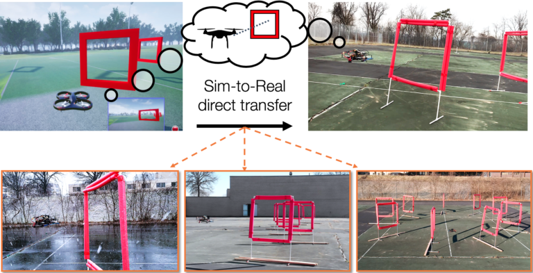
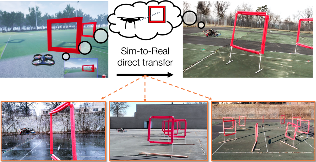
Figure 1. Our framework uses simulation to learn a low-dimensional state representation using multiple data modalities. This latent vector is used to learn a control policy which directly transfers to real-world environments. We successfully deploy the system under various track shapes and weather conditions, ranging from sunny days to strong snow and wind.
The Task
In first person view (FPV) drone racing, expert pilots can plan and control a quadrotor with high agility using a noisy monocular camera feed, without compromising safety. We attempted to mimic this ability with our framework, and tested it with an autonomous drone on a racing task.
We used a small agile quadrotor with a front facing camera, and our goal was to train a neural network policy to navigate through a previously unknown racing course. The network policy used only images from the RGB camera.
While autonomous drone racing is an active research area, most of the previous work so far has focused on engineering a system augmented with extra sensors and software with the sole aim of speed. Instead, we aimed to create a computational fabric, inspired by the function of a human brain, to map visual information directly to correct control actions. We achieved this by first converting the high-dimensional sequence of video frames to a low-dimensional representation that summarizes the state of the world.
 https://www.microsoft.com/en-us/research/uploads/prod/2020/03/DARPA-2-300x225.png 300w, https://www.microsoft.com/en-us/research/uploads/prod/2020/03/DARPA-2-80x60.png 80w, https://www.microsoft.com/en-us/research/uploads/prod/2020/03/DARPA-2-240x180.png 240w" sizes="(max-width: 608px) 100vw, 608px" />
Figure 2: Quadrotor used for the experiments. Images from the front-facing camera are processed on the onboard computer.
Our Approach
Our approach was to learn a visuomotor policy by decomposing the problem into the tasks of (1) building useful representations of the world and (2) taking a control action based on those representations. We used AirSim, a high-fidelity simulator, in the training phase and then deployed the learned policy in the real world without any modification. Figure 1 depicts the overall concept, showing a single perception module shared for simulated and real autonomous navigation.
A key challenge here is the models have to be robust to the differences (e.g., illumination, texture) between simulation and the real world. To this end, we used the Cross-Modal Variational Auto Encoder (CM-VAE) framework for generating representations that closely bridge the simulation-reality gap, avoiding overfitting to the eccentricities of synthetic data.
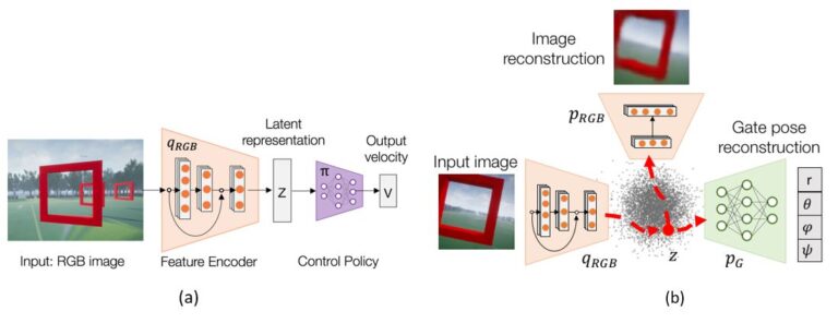
The first data modality considered the raw unlabeled sensor input (FPV images), while the second characterized state information directly relevant for the task at hand. In the case of drone racing, the second modality corresponds to the relative pose of the next gate defined in the drone’s coordinate frame. We learned a low-dimensional latent environment representation by extending the CM-VAE framework. The framework uses an encoder-decoder pair for each data modality, while constricting all inputs and outputs to and from a single latent space (see Fig. 3b).
The system naturally incorporated both labeled and unlabeled data modalities into the training process of the latent variable. Imitation learning was then used to train a deep control policy that mapped latent variables into velocity commands for the quadrotor (Fig. 3a).
 https://www.microsoft.com/en-us/research/uploads/prod/2020/03/Darpa-3-300x116.jpg 300w, https://www.microsoft.com/en-us/research/uploads/prod/2020/03/Darpa-3-1024x395.jpg 1024w, https://www.microsoft.com/en-us/research/uploads/prod/2020/03/Darpa-3-768x296.jpg 768w" sizes="(max-width: 1097px) 100vw, 1097px" />
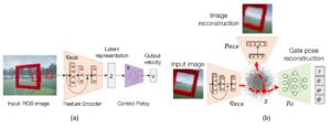
Figure 3. (a) Control system architecture. The input image from the drone’s video is encoded into a latent representation of the environment. A control policy acts on the lower-dimensional embedding to output the desired robot control commands. (b) Cross-modal VAE architecture. Each data sample is encoded into a single latent space that can be decoded back into images, or transformed into another data modality such as the poses of gates relative to the unmanned aerial vehicle (UAV).
Learning to understand the world
The role of our perception module was to compress the incoming input images into a low-dimensional representation. For example, the encoder compressed images of size 128 X 72 in pixels (width X height) from 27,648 original parameters (considering three color channels for RGB) down to the most essential 10 variables that can describe it.
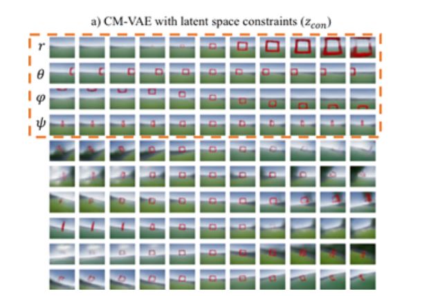
We interpreted the robot’s understanding of the world by visualizing the latent space of our cross-modal representations (see Figure 4). Despite only using 10 variables to encode images, the decoded images provided a rich description of what the drone can see ahead, including all possible gates sizes and locations, and different background information.
 https://www.microsoft.com/en-us/research/uploads/prod/2020/03/Fig-4-DARPA-300x202.jpg 300w" sizes="(max-width: 636px) 100vw, 636px" />
Figure 4. Visualization of imaginary images generated from our cross-modal representation. The decoded image directly captures the relative gate pose background information.
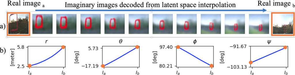
We also showed that this dimensionality compression technique is smooth and continuous. Figure 5 displays a smooth imaginary path between two images taken in real life. Given the cross-modal nature of the representation, we can see both decoded images and gate poses for the intermediate values.
 https://www.microsoft.com/en-us/research/uploads/prod/2020/03/DARPA-7-300x76.png 300w, https://www.microsoft.com/en-us/research/uploads/prod/2020/03/DARPA-7-768x196.png 768w, https://www.microsoft.com/en-us/research/uploads/prod/2020/03/DARPA-7-1536x391.png 1536w, https://www.microsoft.com/en-us/research/uploads/prod/2020/03/DARPA-7.png 1951w" sizes="(max-width: 1024px) 100vw, 1024px" />
Figure 5: Visualization of smooth latent space interpolation between two real-world images. The ground-truth and predicted distances between camera and gate for images A and B were (2.0, 6.0) and (2.5, 5.8) meters respectively.
Results
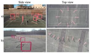
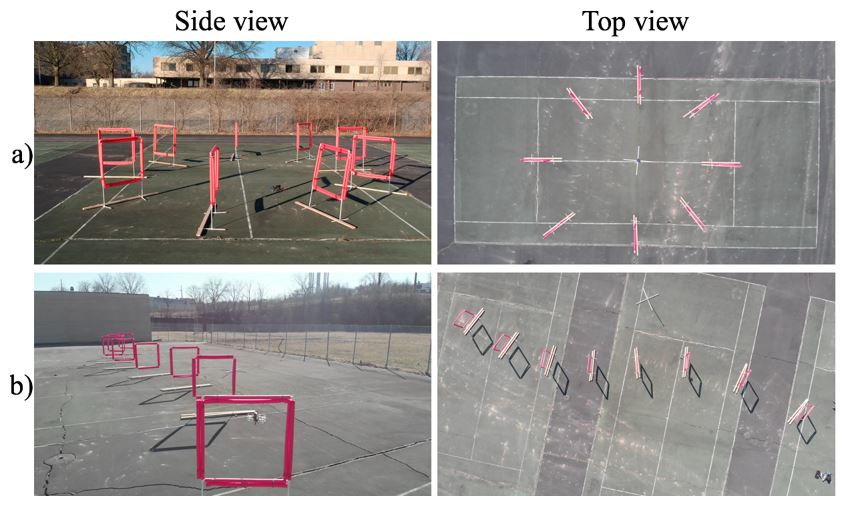
To show the capabilities of our approach on a physical platform, we tested the system on a 45-meter-long S-shaped track with 8 gates, and on a 40-meter-long circular track with 8 gates, as shown in Figure 6. Our policy using a cross-modal representation significantly outperformed end-to-end control policies and networks that directly encoded the position of the next gates, without reasoning over multiple data modalities. To show the capabilities of our approach on a physical platform, we test the system on an S-shaped track with eight gates and 45 meters of length, and on a circular track with eight gates and 40 meters of length, as shown in Figure 6. Our policy that uses a cross-modal representation significantly outperforms end-to-end policies, and networks that directly encode the position of the next gates, without reasoning over multiple data modalities.
 https://www.microsoft.com/en-us/research/uploads/prod/2020/03/DARPA-7-300x178.jpg 300w, https://www.microsoft.com/en-us/research/uploads/prod/2020/03/DARPA-7-768x456.jpg 768w" sizes="(max-width: 864px) 100vw, 864px" />
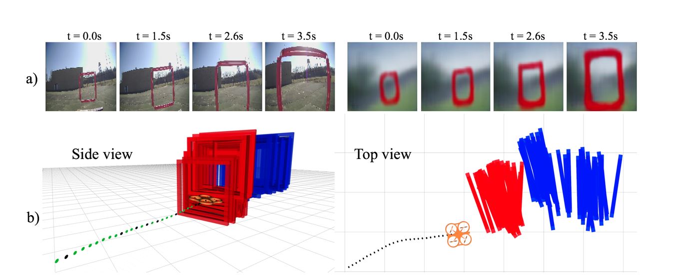
Figure 6: Side and top view of the test tracks: a) Circuit track, and b) S-shape track.
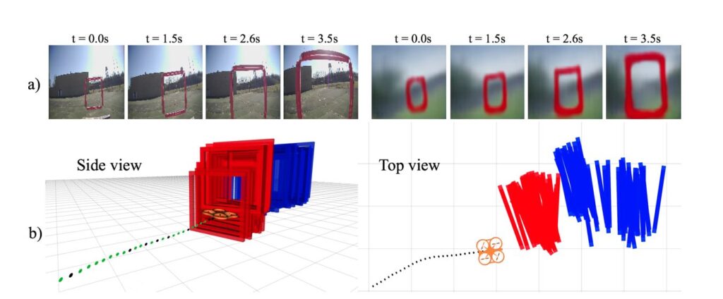
The performance of standard architectures dropped significantly when deployed in the real-world after training in simulation. Our cross-modal VAE, on the other hand, can still decode reasonable values for the gate distances despite being trained purely on simulation. For example, Fig. 7 displays the accumulated gate poses decoded from direct image to pose regression and from our framework, during three seconds of a real flight test. Direct regression results in noisy estimated gate positions, which are farther from the gate’s true location.
 https://www.microsoft.com/en-us/research/uploads/prod/2020/03/DARPA-9-300x124.jpg 300w, https://www.microsoft.com/en-us/research/uploads/prod/2020/03/DARPA-9-768x318.jpg 768w, https://www.microsoft.com/en-us/research/uploads/prod/2020/03/DARPA-9.jpg 1353w" sizes="(max-width: 1024px) 100vw, 1024px" />
Fig 7. Analysis of a three-second flight segment. a) Input images and their corresponding images decoded by the CM-VAE; b) Time history of gate center poses decoded from the CM-VAE (red) and regression (blue). The regression representation has significantly higher offset and noise from the true gate pose, which explains its poor flight performance.
We take our perception-control framework to its limits by testing it in visual conditions never seen before during the training phase in simulation. Fig. 8 shows examples of successful test cases under extreme visually-challenging conditions: a) indoors, with a blue floor containing red stripes with the same red tone as the gates, and Fig. 8 b-c) during heavy snows. Despite the intense visual distractions from background conditions, the drone was still able to complete the courses by employing our cross-modal perception module.
Challenges and Future
By separating the perception-action loop into two modules and incorporating multiple data modalities into the perception training phase, we can avoid overfitting our networks to non-relevant characteristics of the incoming data. For example, even though the sizes of the square gates were the same in simulation and physical experiments, their width, color, and even intrinsic camera parameters are not an exact match. The multiple streams of information that are fed into the cross-modal VAE aid in implicit regularization of the learned model, which leads to better generalization over appearance changes.
We believe our results show great potential for helping in real-world applications. For example, if an autonomous search and rescue robot is better able to recognize humans in spite of differences in age, size, gender, ethnicity and other factors, that robot has a better chance of identifying and retrieving people in need of help.
An unexpected result we came across during our experiments is that combining unlabeled real-world data with the labeled simulated data for training the representation models did not increase overall performance. Using simulation-only data worked better. We suspect that this drop in performance occurs because only simulated data was used in the control learning phase with imitation learning. One interesting direction for future work we are investigating is the use of adversarial techniques for lowering the distance in latent space between similar scenes encoded from simulated and real images. This would lower the difference between data distributions during training and testing phases.
We envision extending the approach of using unlabeled data for policy learning. For example, besides images, can we combine distinct data modalities such as laser measurements and even sound for learning representations of the environment? Our success with aerial vehicles also suggests the potential to apply this approach to other real-world robotics tasks. For instance, we plan to extend our approach to robotic manipulation which also requires a similar ability to interpret inputs in real time and make decisions while ensuring safe operations.
LightWare is delighted to launch our new long range microLiDAR™. The SF30/D is ideal for altitude management above 400 feet. Each SF30/D is range tested in the bright African sun to ensure super performance in the hands of our customers.
The SF30/D laser measurement sensor provides real time, accurate altitude (AGL) measurements for UAVs. The lightweight 36 gram design features a time-of-flight range up to 200 meters (656 feet), and an update rate up to 20K readings per second. Typical applications: The SF30/D is ArduPilot compatible, and laser Class 1M eye safe.
Now in stock: LightWare SF30/D
Greetings.
This is a cross-post from the ArduPilot blog.
UAVCAN was first announced six years ago, in early 2014, as an RFC doc published on this website. Over the following few years, it saw adoption in numerous systems – mostly UAV, naturally, but also including spacecraft, micromobility vehicles, and even racing cars. The vast empirical data collected from fielded systems over the years allowed us to identify the weak points in the design and eventually enabled us to come up with the rectified, field-proven stable design which we call UAVCAN v1.0.
The stable version was first announced about 18 months ago. Expectedly, the fact that v1.0 breaks wire compatibility with the original design based on that first RFC caused concern among the adopters. The resistance is understandable and we are certainly not blind to the costs of migrating the existing ecosystem to a different format, but we are confident that the costs are justified. This is because the design imperfections of v0 if left unrectified would be far costlier to the ecosystem in the long term than a breaking change introduced now.
The design issues of v0 that affect the UAV industry the most were neatly summarized by Tridge himself in a thread on the UAVCAN forum. As one can see from reading the thread, his input was incorporated into the v1 design. Specifically, that includes an improved approach to data type extensibility and versioning, and the ability to construct heterogeneous networks where the experimental v0 can co-exist with the stable UAVCAN v1.
While we are at it, I would like to quote myself from the thread on the necessity of the breaking change:
UAVCAN v1 is being deployed in highly complex vehicular applications where v0 could not be used due to its inherent limitations, only some of which were reviewed here. The most critical issue in v0 is the syntax-semantics entanglement, which by itself was an underlying cause for some other, more apparent issues, such as the over-specification of the standard data types. UAVCAN v0 is a great protocol for trivial UAV applications with unsophisticated hardware setups and straightforward design requirements, such as those that can be found in various basic industrial applications or hobby machines. The problem of v0 is that it breaks outside of that domain, and it is not possible to take v1 out of there without breaking backward compatibility. While the transition is painful, it is beneficial for everyone, especially the existing adopters of v0, because the much-improved architecture of v1 will increase the reach and coverage of its ecosystem, effectively increasing the available product options for integrators and at the same time increasing the reachable market for product manufacturers.
The improved ecosystem management policies and the new technical capabilities enable a very long design lifespan for v1 […]
Considering the state of the industry at large, one can see that v1 is a fundamental improvement over v0.
Having discussed and defined the design requirements, the last few months were spent updating the Specification and finalizing the reference implementation libraries. This work was completed just a few days ago, yielding the following results:
- Libcanard v1 – an updated version of the venerable Libcanard v0. It comes with 100% test coverage and a rigorous timing/resource utilization model for the benefit of high-integrity embedded systems.
- PyUAVCAN v1 – a redesigned from scratch version of the old PyUAVCAN v0 based on async API.
- The Crash Course, covering the basics and explaining the differences from v0.
I am happy to report that v1 is already here and one can build an actual v1 hardware node. I am hopeful that the ArduPilot community will find it just as useful as we do, and that it would find its way into AP_Periph as the default option along with v0.
While v1 is already usable, there is still some work to be done. We are grateful to NXP Semiconductors and other major adopters for helping us advance the project, but there is always more work than we can handle, so we can use all the help we can get. The current areas of focus are outlined in the recent UAVCAN Roadmap.
UAVCAN has been extensively validated in the field across many industries over the last six years, which gives us the confidence to state that the design lifespan of v1 should exceed at least a decade.
Hello DIY’ers!
I stumbled upon this 2015 post from Gerard Toonstra and am looking to build a similar setup:
There’s a ton of useful information in his post/blog, but since several of the links have now aged and technology has advanced, I thought I’d create a new thread on the topic.
I have a Phantom 4 Pro which I have a few years of surveying experience with (I’m not a licensed surveyor) doing aerial mapping and using Pix4D, so that part's covered. What I don’t have is $30k for an RTK unit lol.
I'm looking to build five small GPS "boxes" to place on my GCPs in order to increase the relative accuracy of my maps in all three axes. After a few days of research, I have a better understanding of how to build said boxes, but not enough to pull the trigger on the required components yet. Here’s where I’m at:
- Accuracy: Relative accuracy is more important than absolute accuracy in my case, at least for now. I’m shooting for sub-20cm accuracy after letting them log for 1-2 hours and processing using PPK. Getting down to sub-10cm without needing a base would be awesome, but I’m not sure that’s realistic.
- Arduino+Shields vs. Raspberry Pi 4: I don’t have any experience with either option. I plan on getting familiar with one or the other so I can build these boxes now as well as a mapping UAV in the future. It seems Arduino+Shields is the simpler and cheaper route, but I like how the Raspberry Pi 4 comes with so much capability packed right on the original board. I’d happily pay the extra money for the Pi if it makes sense for this project. If I go with the Pi 4, is 2gb enough memory or should I go with the 4gb version?
- GPS Module: Although the ZED-F9P claims to be around 1cm accuracy with RTK, it seems a bit overkill if using it for static logging and PPK. As for cheaper GPS modules I'm looking at the M8N or M8T, unless there's another capable/cost-effective module that I'm unaware of.
- Usability/IO: I'd like to be able to have my settings saved for the boxes instead of configuring them before each job/flight (EEPROM?) so that I just flip a switch and they eventually start recording until I turn them off. A few LEDs (or mini LCD screen) to indicate battery charge and satellite fix/data activity.
- Runtime: Battery operated, rechargeable. If I had to let them collect for let’s say four hours would one or two 18650s do the trick? AAA’s? I’ll likely be logging at 1Hz.
- Communication: Do I need antennas for them if they’re not communicating to one-another?
- Data Storage: Stored onboard each of the boxes. I assume via SD cards.
- Programming: I have a little coding experience, I’m sure I can learn what’s required.
- Enclosures: I’ll model and 3d print them.
- Random unknowns: Data Logger (Arduino + Sparkfun Logomatic v2? Do Raspberry Pi’s already come with data logging capabilities?), Software (u-Center looks nifty, not sure if that’s needed for PPK though), Data Processing (RTKLIB? RCTM?).
- Budget: A few thousand USD, I realize that generally speaking higher accuracy = more money.
- Working Location: NW United States.
I know this is an absolute mountain of questions, many of which are subjective, so any spattering of info would be greatly appreciated! I’ll be sure to share my build-in-progress and performance of the boxes here in case others find it useful. Thanks!
The latest version of Pi-Connect Lite board has been released. It's a minor increment over the previous version, with better power switch placement and clearer labels.
It is ideal for anyone wanting a quick and simple way to integrate a Raspberry Pi board with a MAVLink-based flight controller, with a high capacity power supply and Pixhawk-standard JST-GH telemetry connector. It also features a power switch for safely shutting down the Pi.
Take a look at the full specifications over at: https://www.rpanion.com/product/pi-connect-lite/
Cool research from Virginia Tech using a 3DR Solo to do wind measurement:
All multirotor drones can be used as wind sensors, providing wind profiles on demand, anywhere, with higher spatiotemporal resolution and a fraction of the cost of other methods. See the free open-access paper https://lnkd.in/em95QEa on how to obtain wind profiles from the drone's dynamic response to wind-induced perturbations. The study was led by soon-to-graduate Virginia Tech
Newly emerged virgin honey bee queens become inseminated in flight by multiple male honey bees (drones) in elevated regions called Drone Congregation Areas (DCAs). These DCAs are areas five to 60 meters above ground and 30 to 200 meters in diameter. They can persist in the same place for dozens of years - longer than the life of any queen (a couple years) and much longer than the life of a drone (21-32 days!). This raises a question: How do queens and drones know where the DCA is year after year. Since drones and queens arrive at DCAs from multiple colonies, it is believed that DCAs exist so that queens can maximize the genetic diversity in their colony. Somehow, they all know where to go to link up.
To try to solve this mystery, DCA research has traditionally used helium balloons dangling pheromone lures to locate DCAs. It is slow and tedious work. In 2015, I wrote about multirotor pilots encountering DCAs in a blog post called "Drones Make Love Not War" (http://www.beehacker.com/wp/?p=1243). In that posting, I linked to several YouTube videos showing 'angry' bees that I pointed out were really just horny bees.
My good friend and UGA Master Beekeeper Julia Mahood has created a website (http://mapmydca.com/) for multirotor pilots to report DCAs they encounter. If you are willing to search for DCAs, she provides plenty of information to get you started. If you are not a multirotor pilot, you can help our research by forwarding this post to someone who is a multirotor pilot.
Thanks for your support.
Hi,
I would like to share our last challenge. I think it is probably the longest flight with a hybrid gas-electric drone:
In December 2015 we published our first record:
https://diydrones.com/profiles/blogs/3hr-10min-endurance-test-with-hybrix-quadrotor-by-quaternium
All this years we have been doing small improvements, A lot of small improvements that make a very big difference. With the EFI we have seen lower consumption far beyond what we thought possible. The weight of all the components has fallen, The generator has increased the available power....
We are very happy with the result, but I also have to tell you that it is not the maximum time we can do.
Obviously it is not a flight time that a customer can use, It is not very practical to fly with 16liters of fuel in a 25kg MTOW drone. But it does show that it is possible to fly for 6 hours with a payload of for example 2kg
I hope you like it!
jlcortex
Hi,
we implemented radar/laser altimeter support for DJI M210/M210V2 drones (in addition to previously supported M600/M600Pro/A3).
Set consists of UgCS SkyHub onboard computer, radar or laser altimeter, set of cables and software.
In general, we recommend using a radar altimeter (finally we selected http://en.nanoradar.cn/Article/detail/id/372.html).
After 2 years of practice and feedback from our customers, we decided that laser altimeters have too many restrictions - they don't work reliable under the bright sun, light fog, over water.
Internally the system is pretty complex (diagram for A3 is below, for M210 is pretty the same), but it works :)
Full description and documentation here - https://industrial.ugcs.com/true-terrain-following
UgCS
The past few years have seen tremendous progress in reinforcement learning (RL). From complex games to robotic object manipulation, RL has qualitatively advanced the state of the art. However, modern RL techniques require a lot for success: a largely deterministic stationary environment, an accurate resettable simulator in which mistakes – and especially their consequences – are limited to the virtual sphere, powerful computers, and a lot of energy to run them. At Microsoft Research, we are working towards automatic decision-making approaches that bring us closer to the vision of AI agents capable of learning and acting autonomously in changeable open-world conditions using the limited onboard compute. Project Frigatebird is our ambitious quest in this space, aimed at building intelligence that can enable small fixed-wing uninhabited aerial vehicles (sUAVs) to stay aloft purely by extracting energy from moving air.
Let’s talk hardware
Snipe 2, our latest sUAV, pictured above, exemplifies Project Frigatebird’s hardware platforms. It is a small version of a special type of human-piloted aircraft known as sailplanes, also called gliders. Like many sailplanes, Snipe 2 doesn’t have a motor; even sailplanes that do, carry just enough power to run it for only a minute or two. Snipe 2 is hand-tossed into the air to an altitude of approximately 60 meters and then slowly descends to the ground—unless it finds a rising air current called a thermal (see Figure 2) and exploits it to soar higher. For human pilots in full-scale sailplanes, travelling hundreds of miles solely powered on these naturally occurring sources of lift is a popular sport. For certain birds like albatrosses or frigatebirds, covering great distances in this way with nary a wing flap is a natural-born skill. A skill that we would very much like to bestow on Snipe 2’s AI.
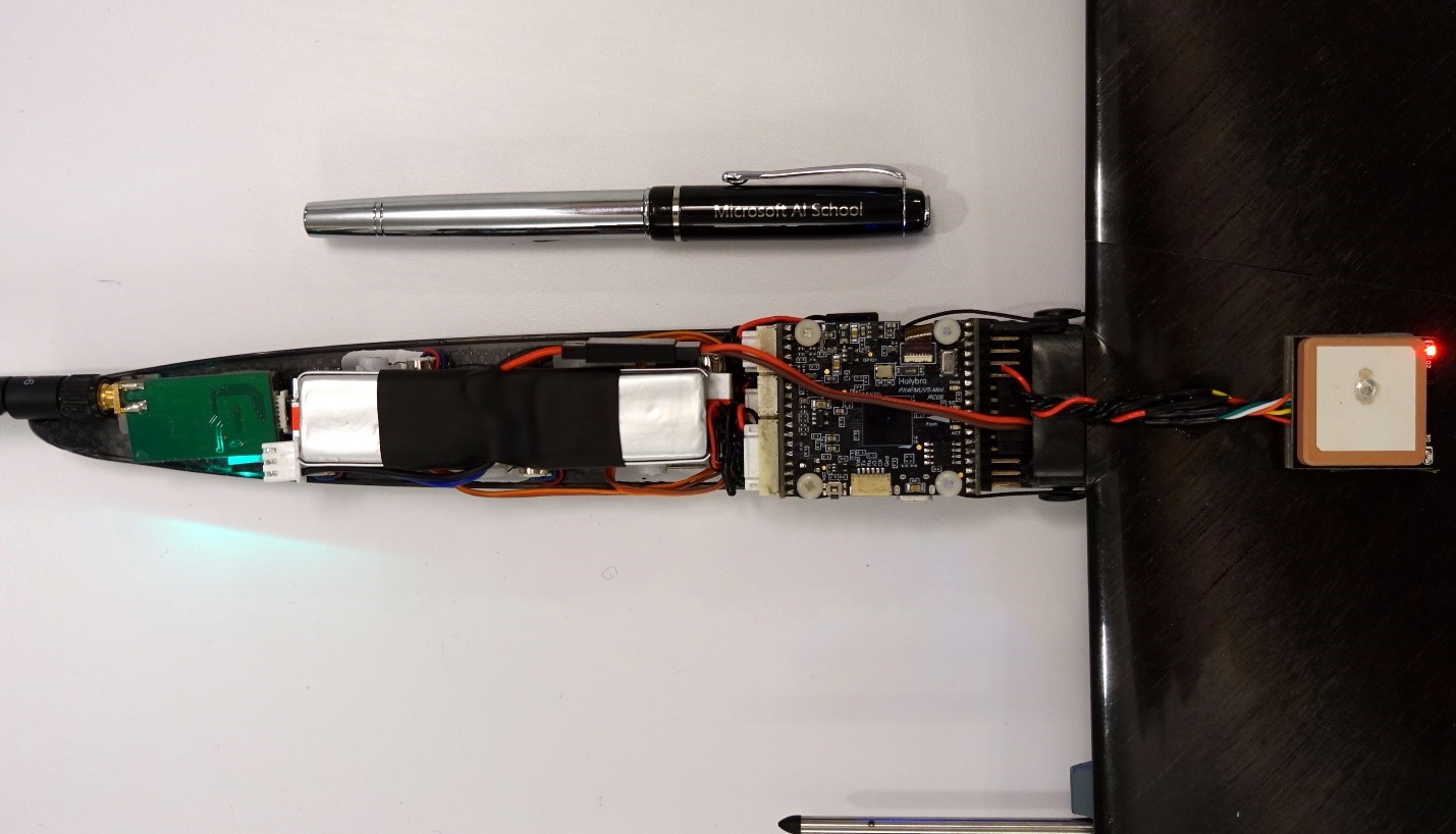
Figure 1: the layout of hardware for autonomous soaring in Snipe 2’s narrow fuselage.
Snipe 2’s 1.5 meter-wingspan airframe weighs a mere 163 grams, its slender fuselage only 35 mm wide at its widest spot. Yet it carries an off-the-shelf Pixhawk 4 Mini flight controller and all requisite peripherals for fully autonomous flight (see Figure 1.) This “brain” has more than enough punch to run our Bayesian reinforcement learning-based soaring algorithm, POMDSoar. It can also receive a strategic, more computationally heavy, navigation policy over the radio from a laptop on the ground, further enhancing the sUAV’s ability to find columns of rising air. Alternatively, Snipe 2 can house more powerful but still sufficiently compact hardware such as Raspberry Pi Zero to compute this policy onboard. Our larger sailplane drones like the 5-meter wingspan Thermik XXXL can carry even more sophisticated equipment, including cameras and a computational platform for processing their data in real time for hours on end. Indeed, nowadays the only barrier preventing winged drones from staying aloft for this long on atmospheric energy alone in favorable weather is the lack of sufficient AI capabilities.
Reaching higher
Why is building this intelligence hard? Exactly because of the factors that limit modern RL’s applicability. Autopilots of conventional aircraft are built on fairly simple control-based approaches. This strategy works because an aircraft’s motors, in combination with its wings, deliver a stable source of lift, allowing it to “overpower” most of variable factors affecting its flight, for example, wind. Sailplanes, on the other hand, are “underactuated” and must make use of – not overpower – highly uncertain and non-stationary atmospheric phenomena to stay aloft. Thermals, the columns of upward-moving air in which hawks and other birds are often seen gracefully circling, are an example of these stochastic phenomena. A thermal can disappear minutes after appearing, and the amount of lift if provides varies across its lifecycle, with altitude, and with distance from the thermal center. Finding thermals is a difficult problem in itself. They cannot be seen directly; a sailplane can infer their size and location only approximately. Human pilots rely on local knowledge, ground features, observing the behavior of birds and other sailplanes, and other cues, in addition to instrument readings, to guess where thermals are. Interpreting some of these cues involves simple-sounding but nontrivial computer vision problems—for example, estimating distance to objects seen against the background of featureless sky. Decision-making based on these observations is even more complicated. It requires integrating diverse sensor data on hardware far less capable than a human brain, and accounting for large amounts of uncertainty over large planning horizons. Accurately inferring the consequences of various decisions using simulations, a common approach in modern RL, is thwarted under these conditions by the lack of onboard compute and energy to run it.

Figure 3: (Left) A schematic depiction of air movement within thermals and a sailplane’s trajectory. (Right) A visualization of an actual thermal soaring trajectory from one of our sUAVs’ flights.
Our first steps have focused on using thermals to gain altitude:
- Our RSS-2018 paper was the first autonomous soaring work to deploy an RL algorithm for exploiting thermals aboard an actual sailplane sUAV, as opposed to simulation. It also showed RL’s advantage at this task over a strong baseline algorithm based on control and replanning, an instance of a class of autonomous thermaling approaches predominant in prior work, in a series of field tests. Our Bayesian RL algorithm POMDSoar deliberatively plans learning about the environment and exploiting the acquired knowledge. This property gives it an edge over more traditional soaring controllers that update their thermal model and adjust their thermaling strategy as they gather more data about the environment, but don’t take intentional steps to optimize the information gathering.
- Our IROS-2018 paper studied ArduSoar, a control-based thermaling strategy. We have found it to perform very well given its approach that plans based on the current most likely thermal model. As a simple, robust soaring controller, ArduSoar has been integrated into ArduPlane, a major open-source autopilot for fixed-wing drones.
Figure 4: An animated 3D visualization of a real simultaneous flight of two motorized Radian Pro sailplanes, one running ArduSoar and another running POMDSoar. Use the mouse to change the viewing angle, zoom, and replay speed. At the end, one of the Radians can be seen engaging in low-altitude orographic soaring near a tree line, getting blown by a wind gust into a tree, and becoming stuck there roughly 35 meters above the ground – a reality of drone testing in the field. After some time, the Radian was retrieved from a nearby swamp and repaired. It flies to this day.
We released both POMDSoar and ArduSoar as part of Frigatebird autopilot on Github, which is based on a fork of ArduPlane.
On a wing and a simulator
Although Project Frigatebird’s goal is to take RL beyond simulated settings, simulations play a central role in the project. While working on POMDSoar and ArduSoar, we saved a lot of time by evaluating our ideas on a simulator in the lab before doing field tests. Besides saving time, simulators allow us to do crucial experiments that would be very difficult to do logistically in the field. This applies primarily to long-distance navigation, where simulation lets us learn and assess strategies over multi-kilometer distances over various types of terrain, conditions we don’t have easy access to in reality.
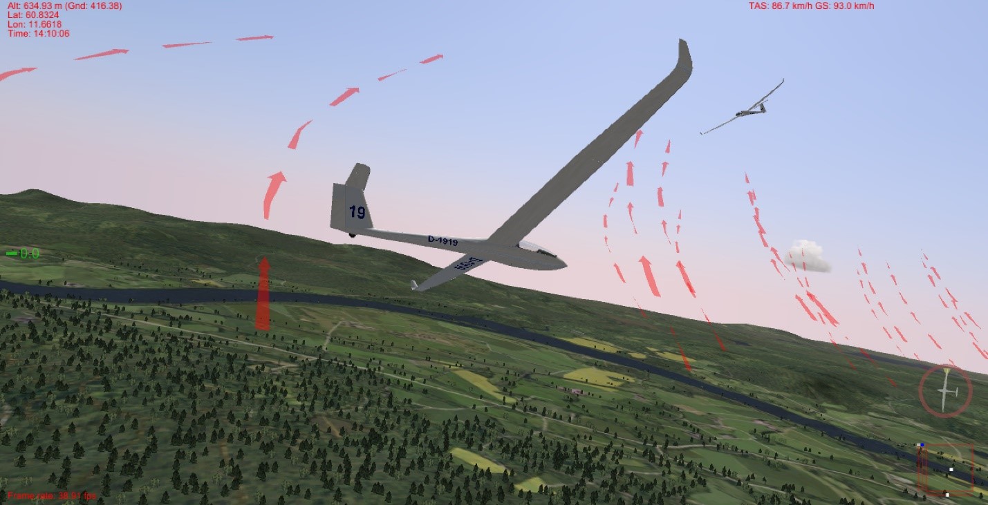
Figure 5: Software-in-the-loop simulation in Silent Wings. A Frigatebird-controlled LS-8b sailplane is trying to catch a thermal where another sailplane is already soaring on a windy day near Starmoen, Norway. For debugging convenience, Silent Wings indicates the centers of thermals and ridge lift, which are invisible in reality, with red arrows (this visualization can be disabled).
To facilitate such experimentation for other researchers, we released a software-in-the-loop (SITL) integration between Frigatebird and a soaring flight simulator, Silent Wings. Silent Wings is renowned for the fidelity of its soaring flight experience. Importantly for experiments like ours, it provides the most accurate modelling of the distribution of thermals and ridge lift across the natural landscape as a function of terrain features, time, and environmental conditions that we’ve encountered in any simulator. This gives us confidence that Silent Wings’ evaluation of long-range navigation strategies, which critically rely on these distributions, will yield qualitatively similar results to what we will see during field experiments.
Flight plan
Sensors let sailplane sUAVs reliably recognize when they are flying through a thermal, and techniques like POMDSoar let them soar higher, even in the weak turbulent thermals found at lower altitudes. However, without the ability to predict from a distance where thermals are, the sailplane drones can’t devise a robust navigation strategy from point A to point B. To address this problem, in partnership with scientists from ETH Zurich’s Autonomous Systems Lab, we are researching remote thermal prediction and its integration with motion planning.
Thermals appear due to warmer parts of the ground heating up the air above them and forcing it rise. Our joint efforts with ETH Zurich’s team focus on detecting the temperature differences that cause this process, as well as other useful features from a distance, using infrared and optical cameras mounted on the sailplane, and forecasting thermal locations from them (see Figure 6.) However, infrared cameras cannot “see” such minute temperature variations in the air, and not every warm patch on the ground gives rise to a thermal, making this a hard but exciting problem. Integrating the resulting predictions with reinforcement learning for motion planning raises research challenges of its own due to the uncertainty in the predictions and difficulties in field evaluation of this approach.

Figure 6: A schematic of a sailplane predicting thermal locations in front of itself by mapping the terrain with infrared and optical cameras. Image provided by ETH Zurich’s Autonomous Systems Lab.
Crew
Building intelligence for a robotic platform that critically relies on, not merely copes with, highly variable atmospheric phenomena outdoors so that it can soar as well as the best soarers – birds! – takes expertise far beyond AI itself. To achieve our dream, we have been collaborating with experts from all over the world. Iain Guilliard, a Ph.D. student from the Australian National University and a former intern at Microsoft Research, has been the driving force behind POMDSoar. Samuel Tabor, a UK-based autonomous soaring enthusiast, has developed the alternative control-based ArduSoar approach and helped build the software-in-the-loop integration for Silent Wings. The Frigatebird autopilot, which includes POMDSoar and ArduSoar, is based on the ArduPlane open-source project and on feedback from the international community of its developers. We are researching infrared/optical vision-aided thermal prediction with our partners Nicholas Lawrance, Jen Jen Chung, Timo Hinzmann, and Florian Achermann at ETH Zurich’s Autonomous Systems Lab led by Roland Siegwart. The know-how of all these people augments our project team’s in-house expertise in automatic sequential decision-making, robotics/vision (Debadeepta Dey), and soaring (Rick Rogahn).
(Photo by Dustin Iskandar, CC BY 2.0)
My long-time interest has been in developing insect-type vision for small drones. Properly implemented, I believe that such vision hardware and algorithms will allow small drones to fly safely amidst clutter and obstacles. Of course, I have been following with great interest other approaches to providing autonomy to small drones. Like almost everyone else, I am in awe at the achievement of Skydio- nice work!
My own work, though, has been to implement similar types of autonomy on much smaller “nano” scale platforms. These are tiny sparrow-sized drones that can fit in your hand and weigh just tens of grams. This is well under the 250-gram threshold the FAA uses to determine if a drone needs to be registered, and certainly much smaller than most commercially available drones. Nano drones have some fantastic advantages- they are small, stealthy, easy to carry, and (in my opinion) inherently safe. They also fit into much tinier spaces than larger drones and can thus get closer to objects that might be inspected.
That small size, however, does not lend itself well to carrying lots of on-board processing, say from a GPU single-board computer. The entire mass of one of my drones (vision and all) weighs less than available GPU boards (especially once you add the required heat sink!). Until single-digit gram GPU modules (inclusive of everything but the battery) are available, I am stuck with much more modest processing levels, say from advanced microcontrollers capable of hundreds of MIPS (million instructions per second) rather than the Teraflops you can get from GPUs. Given most contemporary approaches to vision-based autonomy use VGA- or similar-resolution cameras to acquire imagery and GPUs to process this imagery, you might think implementing vision on a nano drone is not feasible.
Well, it turns out implementing vision on nano drones is quite doable, even without a GPU. In past work, I’ve found you can do quite a lot with just a few hundred to a few thousand pixels. I’ll get into examples below, but first let’s consider what types of solutions flying insects have evolved. If you begin a study on insect vision systems, you will notice two things right away- First, insect vision systems tend to be omnidirectional. Their only blind spots tend to be directly behind them, blocked by the insect’s thorax. Second, insect vision systems have what we would think of as a very low resolution. An agile dragonfly may have about 30,000 photoreceptors (nature’s equivalent of pixels), almost three orders of magnitude less than the camera in your smart phone. And the lowly fruit fly? Only about 800 photoreceptors!
How do insects see the world with such low resolution? Much like contemporary drones, they make use of optical flow. Unlike contemporary drones, which generally use a single camera mounted on the bottom of the drone (to measure lateral drift or motion), insect vision systems measure optical flow in all directions. If the optical flow sensing of a contemporary drone is analogous to one optical mouse looking down, an insect vision system is analogous to hundreds or thousands of optical mice aimed different directions to cover every part of the visual field.
The vision systems of flying insects also include neurons that are tuned to respond to global optical flow patterns that, it is believed, contribute to stability and obstacle avoidance. Imagine yourself an insect ascending in height- the optical flow all around you will be downward as all the objects around you appear to descend relative to you. You can imagine similar global optical flow patterns as you move forward, and yet others as you turn in place, and yet other expanding patterns if you are on a collision course with a wall.
Another trick performed by insects is that when they fly, they make purposeful flight trajectories that cause optical flow patterns to appear in a predictable manner when obstacles are present. Next time you are outside, pay attention to a wasp or bee flying near flowers or their nest- you will see they tend to zig-zag left and right, as if they were clumsy or drunk. This is not clumsiness- when they move sideways, any objects in front of them makes clear, distinct optical flow patterns that not only reveals the presence of what is there but it’s shape. They do this without relying on stereo vision. Essentially you can say flying insects use time to make up for lack of spatial resolution.
Such purposeful flight trajectories can be combined with optical flow perception to implement “stratagems” or holistic strategies that allow the insect to achieve a behavior. For example, an insect can fly down the center of a tunnel by keeping the left and right optical flow constant. An insect can avoid an obstacle by steering away from regions with high optical flow. Biologists have identified a number of different flight control “stratagems”, essentially holistic combinations of flight paths, resulting optical flow patterns, and responses thereto that let the insect perform some sort of safe flight maneuver.
In my work over the past two decades, I have been implementing such artificial insect vision stratagems including flying them on actual drones. At Centeye we took an integrated approach to this (the subject of a future article)- We designed camera or “vision chips” with insect-inspired pixel layouts and analog processing circuitry, matching lenses, and small circuit boards with processors that operate these vision chips. We then wrote matching optical flow and control algorithms and tested them in flight. Nobody at Centeye is just a hardware engineer or just a software engineer- the same group of minds designed all the above, allowing for a holistic and well-integrated implementation. The result was robust laboratory-grade demonstrations of different vision-based control behaviors at known pixel resolutions and processor throughputs. See the list below for specific examples. This list focuses on early implementations, most from a decade or more ago, to emphasize what can be performed with more limited resources. We also include one more recent example using stereo vision, to show that even stereo depth perception can be performed with limited resolution.
Altitude hold (2001), 16-88 pixels, 1-4 MIPS: Have a fixed-wing drone hold its altitude above ground by measuring the optical flow in the downward direction. Video links: https://youtu.be/IYlCDDtSkG8 and https://youtu.be/X6n7VeU-m_o
Avoid large obstacles (2003), 264 pixels, 30 MIPS total: Have a fixed-wing drone avoid obstacles by turning away from directions with high optical flow. Video link: https://youtu.be/qxrM8KQlv-0
Avoid a large cable (2010), 128 pixels, 60 MIPS: Have a rotary-wing drone avoid a horizontal cable by traveling forward in an up-down serpentine path.
Yaw control (2009), 8 pixels, 20 MIPS (overkill): Visually stabilize yaw angle of a coaxial helicopter without a gyro. Video link: https://youtu.be/AoKQmF13Cb8
Hover in place (2009), 250-1024 pixels, 20-32 MIPS: Have a rotary-wing drone hover in place and move in response to changing set points using omnidirectional optical flow. Video links: https://youtu.be/pwjUcFQ9b3A and https://youtu.be/tvtFc49mzgY
Hover and obstacle avoidance (2015), 6400 pixels, 180 MIPS: Have a nano quadrotor hover in place, move in response to changing set points, and avoid obstacles. Video link: https://youtu.be/xXEyCZkunoc
What we see is that a wide variety of control stratagems can be implemented with just a few hundred pixels and with processor throughputs orders of magnitude less than a contemporary GPU. Even omnidirectional stereo vision was implemented with just thousands of pixels. Most notable was yaw control, which was performed with just eight pixels! The above are not academic simulations- they are solid existence proofs that these behaviors can be implemented in the stated resolutions. The listed demonstrations did not achieve the reliability of flying insects, but then again Nature, by evolving populations of insects in the quadrillions over 100 million years, can do more than a tiny group of engineers over a few years.
There are several implications of all this. First, it would seem that the race for more pixel resolution that the image sensor industry seems to be pursuing is not a panacea. Sure- more pixels may yield a higher spatial resolution, bringing out details missed by coarser images, but at the cost of producing much more raw data than what is needed, and certainly much more than what is easily processed if you don’t have a GPU at your disposal!
Second, this begs the question- are GPUs really the cure-all for all situations in which processing throughput is a bottleneck? Don’t get me wrong- I love the idea of having a few teraops to play with. But is this always necessary? For many applications, even those involving vision-based control of a drone, perhaps we are better off grabbing just fewer pixels and using a simpler but better tuned algorithm.
Personally, I am a big fan of the so-called 80/20 principle, which here implies that 80% of the information we can use comes from just 20% of the pixel information. The 80/20 principle is recursive- the top 4% may provide 64% of the value, and taken to an extreme the top fraction of a percent of the pixels or other computational elements of a vision system will still provide within an order of magnitude the information as that of the original set. It might seem like information is thrown away, until you realize that it is much easier to process a thousand pixels than a million. I wonder what other implications there are of this to machine vision and to artificial intelligence in general…
Third, this is very good news for nano drones, or even future insect-sized “pico” drones- if we just need a few thousand pixels and a hundreds of MIPS of processing throughput, current semiconductor processes will allow us to make a vision system within a small fraction of a gram that supports this. Of course, we need the RIGHT thousand pixels and the RIGHT algorithms!
Thank You for indulging me in this. Please let me know what you think.
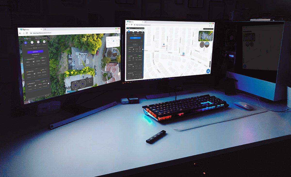
FlytNow Guest Link Sharing offers the capability to share live drone video feed and telemetry with teammates and clients.
Scroll down for the step-by-step tutorial.
Remote Private Access to Drone Fleet, Live Video Feed & Telemetry
Enterprises worldwide are scaling their drone operations, as cost-effective drones become available off-the-shelf, and cloud-based SaaS solutions drive intelligent automation. One of the key drivers of drone fleet adoption is the ability for a variety of stakeholders to participate in drone missions. For example, an inspection of a wind turbine may involve on-site visual observers, remote subject-matter experts, safety managers from regional offices, R&D teams from corporate offices, technology partners — and even UAV regulators who seek insights into such missions before granting waivers for unmanned flights.
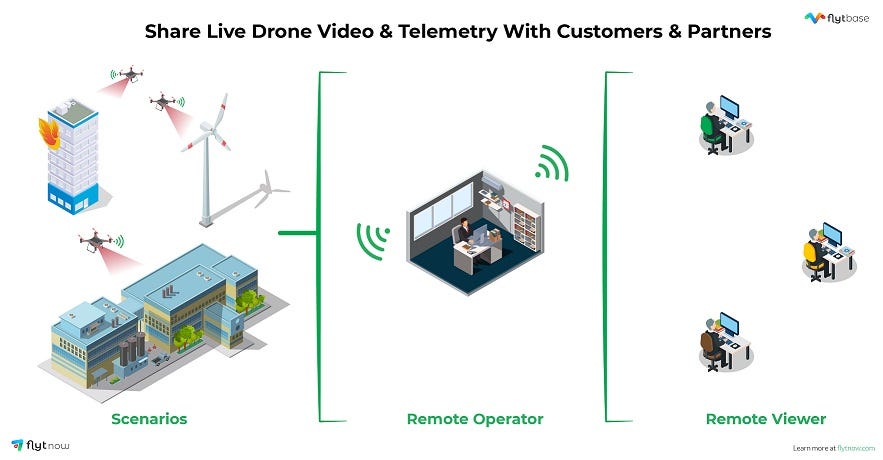
Live, remote drone operations thus require not only low-latency, high-quality video feeds, but also the ability to seamlessly share such video streams across people, geographies, devices and networks. In fact, enterprise drone programs tend to involve a variety of drone hardware — including off-the-shelf drones like DJI Mavic 2 Pro, Mavic 2 Enterprise, Matrice 210/210RTK, M600 Pro, etc., for day-to-day operations and custom drones built using DJI A3, Pixhawk or Cube based autopilots with high-end sensors for rare but critical use-cases.
User-level Access to Drone Missions

Given that privacy and security remain amongst the top concerns in the global drone ecosystem, enterprises have to carefully manage access to drone telemetry, live video streams, navigation, and payloads. With multiple, remote participants in each mission, fine-grained access — based on the roles and responsibilities of each participant — becomes central to successful drone operations.
Guest Link Sharing
It can be argued that many drone operations would be significantly more productive if secure, mission-wise remote viewing can be made available, over the Internet, via a user-friendly interface. Whether it’s a drone service provider monitoring construction sites or whether it’s the in-house drone operations manager supporting his/her colleagues for inspection of infrastructure assets, the access to live video streams — securely & remotely — can create immediate business value by enabling subject-matter experts to make better-informed decisions.
In fact, not only can remote viewers be empowered to access live video feeds in real-time, but remote operators can be given control of the drone, camera gimbal and payloads, with the on-site team serving as safety pilots and visual observers. Automating such live, remote drone operations then becomes the logical next step in the evolution and maturing of enterprise drone programs.
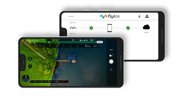
Drone Videos on Mobile Phones
Given the pervasiveness of mobile phones and tablets across businesses in all sectors, it is but natural for drone mission participants to expect these devices to be an integral part of the overall system. This is now easily possible via enterprise-grade mobile apps that can be easily customized, white-labeled and configured — making drone telemetry & videos extremely portable, especially in areas with robust 4G/LTE/5G networks.
Share Live Map Views, Drone Fleet Location, and other Mission-critical Data
Remote access for ‘guest’ participants in drone missions need not be limited to video — since live map views can also be seamlessly shared over the cloud, showing guest viewers the waypoints, flight paths, obstacles, etc. for each mission. Third-party maps can be integrated to overlay drone missions on satellite imagery, specific drones/payloads can provide IR/thermal camera views to remote stakeholders, and missions such as parcel delivery can be remotely monitored not only over the last-mile but all the way to the ‘doorstep’.
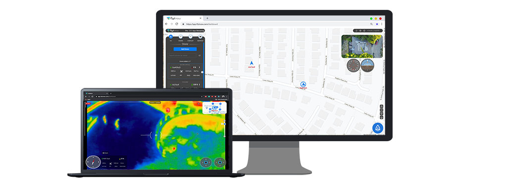
Aerial video streaming is thus becoming the core of drone operations for operators, service providers, system integrators and large enterprises — with secure, user-level access for remote participants the ‘killer app’ of this technology.
Tutorial: How to share live drone video feed and map view using FlytNow
Step 1: Log in to your FlytNow account and connect your drone to the application. Follow the FlytNow getting started guide if you are a first time user.
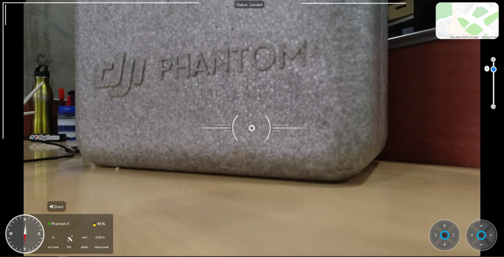
Step 2: Click on the “Share” icon on the video box or button in the Cockpit view
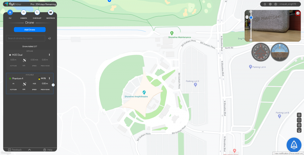
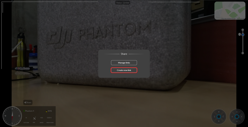
Step 3: Click on “Create new link” to generate a link
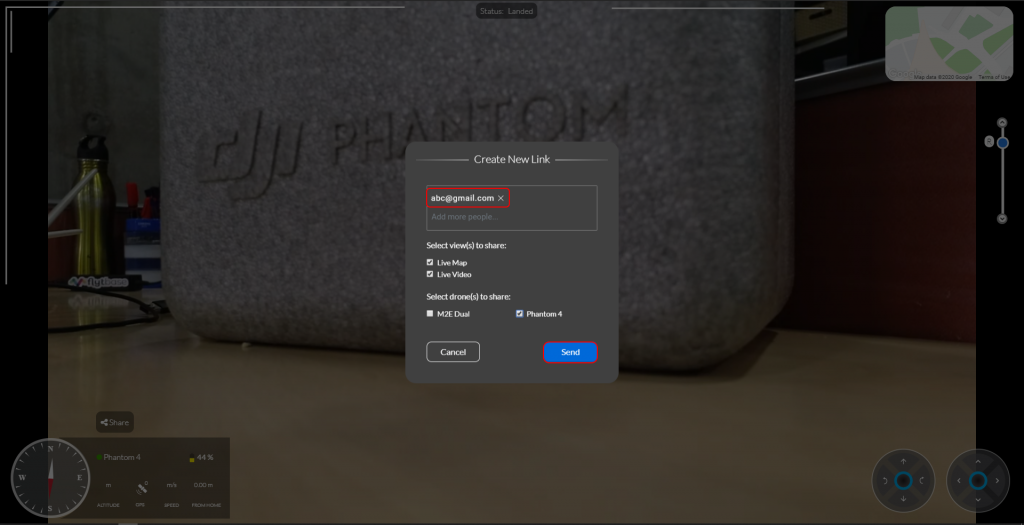
Step 4: Enter your teammate’s or client’s valid email address with whom you wish to share video & map view and click “Send”
Note:
- Choose appropriate options for view and drone access.
- You may enter multiple email addresses
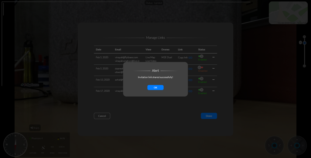
Step 5: Teammate or Client receives an email with a link and Secure PIN
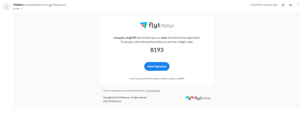
Step 6: Click on the “View Operation” and enter the Secure Pin. Your teammate or client can now securely access live drone feed and telemetry.
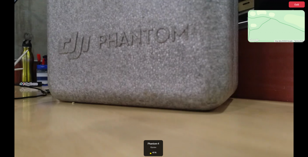
For any questions, you may write to us on info@flytbase.com or visit http://forums.flytbase.com/c/flytnow
How do I Deploy Commercial Drones Easily & Quickly?
FlytBase offers a 28-day free trial for users to explore the FlytNow Pro edition. Customers can add their drone fleets, fly them autonomously, create flight plans & coordinate missions, set geo-fence and checklists, view and store live video footage and integrate drone operations into an existing system.
Start Now and fly your drone(s) via a free trial in 5 Easy Steps.
We are the Dronecoria team, and we believe technology can help to fight the climate crisis.
One of the most effective ways to mitigate climate change and restore the health of our ecosystems is reforestation. To speed up this process we invented Dronecoria; an open source set of tools for large scale, low cost reforestation.
And we just launched a Crowdfunding campaign to improve this objectives, here is the video:
If we raise enough, we will do a pilot test to show the success rate of a reforestation of 30.000 trees in Spain.
Our goal is also to give this drones for free to different environmental organizations around the world: in Australia, Thailand, Brazil, Paraguay, Kenya and Madagascar, to scale up large scale reforestation with drones, and build a community that uses this open technology.
We use Pixhawk 4 as flightboard with Ardupilot/PX4, using the trigger camera settings to open the seed spreading mechanism.
Actually it's a drone designed to have a 8 liters water bottle in the middle as a seed deposit. Is laser-cutted in 5mm plywood, because is cheap, lightweight and easy to replicate, you can check their technical caracteristics.
We are evolving this drone to make it smaller with some motors looking up and others looking down, in order to make easy the transportation by car and airplane.
This is the design of Dronecoria V7 that we are creating with the crowdfunding, is smaller and lighter, and has some improvements too, like a lower center of gravity.
With version 6 we achieve 42 minutes of flight time with no payload and 16 Amp batteries, since we can sow an hectare in around 6 minutes, the operations of this drone are quite fast and we will use smaller batteries to improve the efficiency of the operations.
Please help us to fight deforestation with this open source drones, by contribute today or share the campaign.
Thank you!
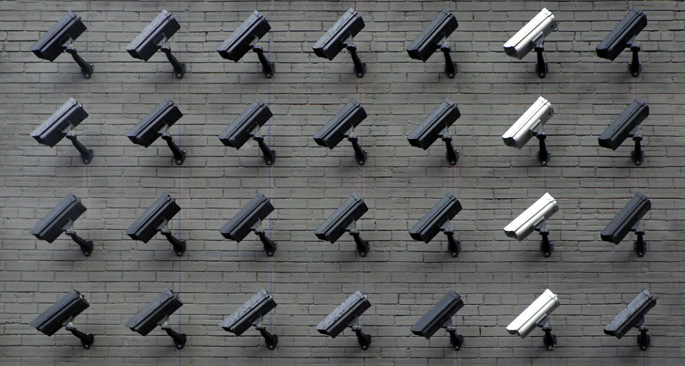
The need for security and surveillance — whether residential or commercial — continues to steadily increase in a world of increasing volatility, uncertainty, complexity, and ambiguity. Privacy, not just security is becoming as much of a concern — with technology playing a central role on both fronts i.e. in violation of privacy and in the provision of security. This is where drones for security come in, powered by reliable hardware and intelligent software.
Traditional security systems (human guards, CCTV cameras, locks, access control systems, etc.) continue to prevail amongst security and surveillance providers. However, new technologies ranging from drones and robots to biometrics, AI and cyber-security have started to capture a larger share of the market. These technologies offer a range of benefits — automation, scalability, remote management, auditability, cost-effectiveness, reliability, mass customization and so on.
Use of Security Drones
Unmanned aerial vehicles (i.e. drones) are already part of the most advanced home and office security systems, with a fleet of drones programmed to launch from their nests, run repeated missions, capture aerial footage of the assets being secured, and return to their nests to charge and prepare for the next mission. By augmenting, if not replacing, human guards and static CCTVs, these ‘eyes in the sky’ can offer faster response to incidents, real-time situational awareness to the central command, live video feeds to remote stakeholders, and even serve as a deterrence to unfriendly elements.
Demand for Drones in Security & Surveillance applications
While regulation remains a challenge for outdoor operations such as aerial security and surveillance using drones, technology has advanced enough to enable drone-in-a-box security systems. These include not just drones, but also autonomous charging pads, weather-proof docking stations, intelligent automation via software, cloud connectivity and live remote operations. The key to large-scale adoption of such drone surveillance systems is their cost-effectiveness; which in turn requires the use of off-the-shelf drone hardware and SaaS-enabled solutions that minimize the upfront capital expenditure.
Importance of UAV for Residential & Commercial Security
Residential security drones have made the news in recent years, but it is industrial and commercial security systems that are seeing faster adoption. This is driven not only by enterprise initiatives in security automation but also by the rapidly increasing costs of human guards for drone security system providers, made worse by constant employee turnover.
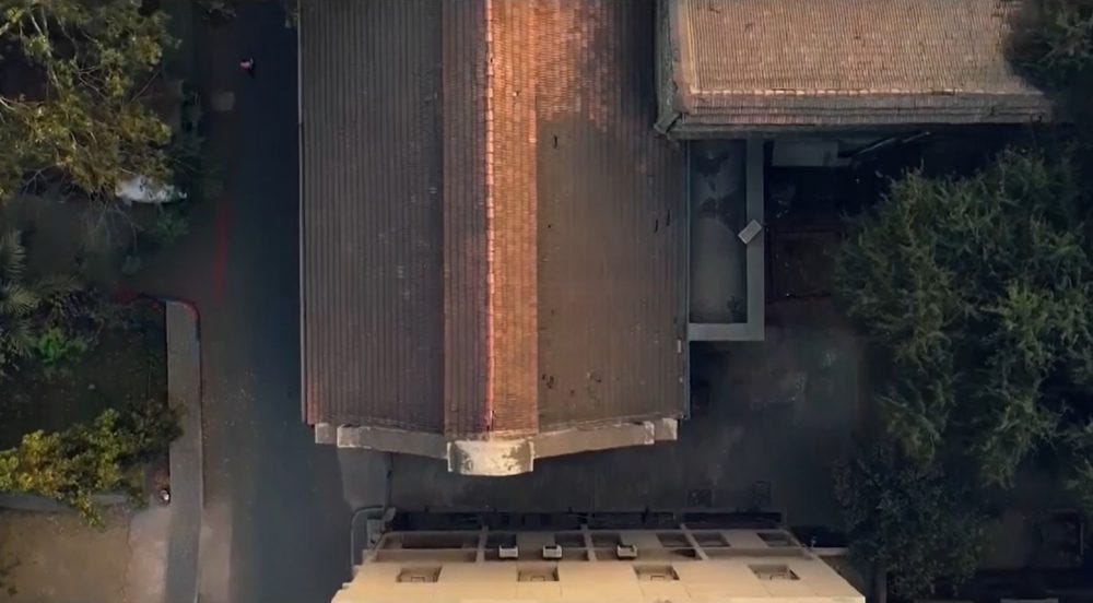
By putting equipment, instead of humans, at risk of harm in case of adverse incidents, aerial surveillance drones minimize risk and enable better-informed decisions during security events. The best surveillance drones can, in fact, be rapidly sent to a location of interest, using GPS navigation and 4G/5G connectivity, to immediately stream live video feeds and even carry payloads such as sirens or warning lights. With thermal and IR cameras easily available, night-time drone patrols and alarms can be an integral part of aerial home/office surveillance systems.
Autonomous UAV Security & Surveillance Solution
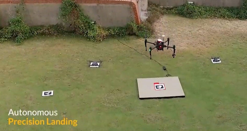
Autonomy is — of course — the key to drones for security, since having human operators involved in UAV surveillance can not only add to the cost, but also introduce the risk of errors, or worse, loss of integrity of security operations. Software-driven automation of drones is thus driving their adoption for home security as well as industrial perimeter security. By defining specific points of interest, ideal schedules, and waypoint-wise camera action, such autonomous UAV security systems can be programmed to operate reliably and continuously and can be rapidly deployed across large swathes of residential or commercial areas. Automatic obstacle detection, collision avoidance and precision landing capabilities further expand the use-cases for drones in this context.
Making Drones Smarter for Security Solutions
By incorporating AI/ML techniques, image processing, and machine vision, drone security systems can even recognize things, track-and-follow intruders, and automatically identify objects that post threats. The physical size and weight of drones are reducing rapidly as the technology matures; such drones can make hard-to-reach locations easily accessible — and make harsh environments more secure — without putting humans at risk of harm.
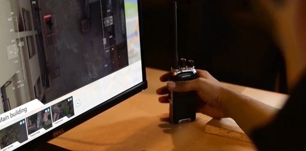
Aerial video surveillance is thus turning out to be the next frontier for the security industry, powered by autonomous drone fleets that are intelligent, cloud-connected and remotely managed.
How can drones be easily, quickly adopted for security use-cases?
FlytBase offers a 28-day free trial for users to explore FlytNow Pro edition and its relevance to specific use-cases for security stakeholders. Customers can add their drone fleets, fly them autonomously, create flight plans & coordinate missions, set geo-fence and checklists, view and store live video footage and integrate drone operations into an existing system.
Start Now and fly your drone(s) via a free trial in 5 Easy Steps.

The commercial drone industry is rapidly maturing – across industries, geographies, use-cases, and business models – thanks to advances in UAV hardware and regulation. An incredibly rich variety of drone hardware has been built, tested, piloted and deployed for enterprise applications – ranging from ‘nano’ category drones for covert surveillance to large, custom-built drones designed to carry multi-kg payloads for last-mile e-commerce delivery.
Nevertheless, a large percentage of commercial use-cases involving drones revolve around the ‘eye in the sky’ capability – making live, high-quality video feeds from drones a key capability of enterprise-grade solutions. With the recent advances in AI/ML technology, the data captured by the drones’ camera can then be automatically processed – in the specific context of that use-case – to derive insights and make informed business decisions.
Live Video Streaming from Drones
Live views of an environment, asset, person, etc. – enabled by drones – are central to use-cases such as situational awareness during natural disasters, inspections of wind turbines and solar farms, intruder detection at secure sites, etc. Drones that stream live video are expected to augment, if not replace, humans as well as fixed monitoring equipment such as CCTVs – driven by their ability to use the 3D space, be remotely operated, carry payloads, be deployed in fleets, and made fully autonomous.
Video from Remote Drone Operations
In use-cases such as public safety, drones can provide live video streams to the emergency operators centers and help accelerate the incident response. In the security & surveillance context, drones can be operated remotely to capture live video, thus preventing humans from being put at risk.

Firefighters can deploy drone fleets all around the incident site to get a 360 degree, real-time video feed and thus employ the most suitable equipment and tactics to control the fire while minimizing safety risks.
From Drone Video Streams To Remote Drone Control
The latency of live video feeds from drones has been brought down to the 500-ms level, and the latency of drone telemetry is in fact much lower at 50ms. Enterprises can thus not only rely on near-real-time video feeds (with quality as high as 4K) from drone fleets – but they can even incorporate remote control of the drone and camera gimbal, into their workflows. Subject-matter experts, for example, need no longer go to the site for asset inspections; instead, they can control the drone from a corporate office, using the live video feed as immediate feedback, saving time, effort and expenses – and improving worker safety at the same time!

A variety of remote stakeholders can thus easily access drone videos simultaneously – with only the drone pilot/operations manager having to be physically on-site. In fact, varying levels of access can be designed to telemetry, images, videos and sensor data – thus ensuring data privacy and security, while empowering the right stakeholders to fulfill their roles in the context of enterprise drone operations.
Enhancing Live Video Streams from Drones
With the availability of cost-effective off-the-shelf drones and airframes, as well as a wide variety of payloads, drone solution providers are crafting the optimal solutions for commercial use-cases. The software of course plays a vital role in enabling drone stakeholders to plan, execute, log, monitor and repeat drone missions; the software will also be crucial in maturing most drone operations from manual to fully autonomous.
However, drone payloads such as thermal cameras, IR cameras, sirens, lights, camera gimbals, charging pads, etc. also are crucial for delivering value. Live video streams from dual cameras in drones can power night-time missions, while the ability to record video streams (on local servers or on the cloud) can support the investigation of security incidents and audits of security services.
Insights from Video Streams from Drones
The rich, real-time image and video data captured by drone cameras serve as a rapidly increasing repository of ‘training data’ for AI/ML algorithms to use as part of intelligent automation of enterprise automation. For example, live video feeds from drones that monitor industrial premises can be complemented with trained AI/ML models that can automatically detect humans, animals, and objects – and trigger security alarms. Similarly, video streams from public safety situations can be automatically analyzed to aid emergency response teams to identify suspects and/or victims in that context. Drone solution providers are in fact rapidly building capabilities to automatically detect weeds, pests, crops, cattle, etc. – with high-quality video data from drone fleets as the key enabler.