Precision Agriculture is a hot topic these days as researchers look for ways to reduce the massive amounts of chemicals that are currently sprayed on food crops. A new research paper describes one of the ways robots may help in Early Season Site-Specific Weed Management (ESSWM). In the study, a UAV equipped with a multispectral camera collected images of sunflower field infested with naturally occurring weeds. Similar imaging techniques using traditional satellite and aerial methods to adjust herbicide distribution have yielded up to 50% reduction in the total amounts of herbicides used. The researchers hope to replicate this process using the less expensive flying robot. From the paper:
Weeds are distributed in patches within crops and this spatial structure allows mapping infested-uninfested areas and herbicide treatments can be developed according to weed presence. The main objectives of this research were to deploy an UAV equipped with either, RBG or multispectral cameras, and to analyze the technical specifications and configuration of the UAV to generate images at different altitudes with the high spectral resolution required for the detection and location of weed seedlings in a sunflower field for further applications of ESSWM. Due to its flexibility and low flight altitude, the UAV showed ability to take ultra-high spatial resolution imagery and to operate on demand according to the flight mission planned.
In the experiment, an MD4-1000 VTOL quadcopter from Microdrones GmbH was used (pictured above). The UAV was equipped with GPS, waypoint navigation software, telemetry logging, and two cameras: an Olympus PEN E-PM1 point-and-shoot digital camera and a Tetracam Mini-MCA-6 six-band multispectral camera. The immediate research goal in this project was to figure out what sensors and image processing techniques would work, so further improvements are quite likely. Now all they need to do is find a catchy name for this technology: weedbots? agridrones? herbidroids? For all the details, read the paper "Configuration and Specifications of an Unmanned Aerial Vehicle (UAV) for Early Site Specific Weed Management" by Jorge Torres-Sánchez, Francisca López-Granados, Ana Isabel De Castro, and José Manuel Peña-Barragán. Read on for some photos showing sample imaging data from the UAV and waypoint navigation paths over the test crop.
Ortho-mosaic of the experimental field. Assembled from individual images taken by UAV from altitude of 100 meters
Screen shot of UAV downlink during programmed flight.
UAV waypoint navigation path over experimental field.
Sample images from UAV: a) RGB camera at 30 meters b) RGB camera at 100 meters c) multispectral camera at 30 meters d) multispectral camera at 100 meters.
[Tim] is getting his drone ready for SparkFun’s 2013 Autonomous Vehicle Competition on June 8th. He has a pretty good start, but was having some problems accurately measuring travel distance. The technique he chose for the task was to glue magnets onto the axles of the vehicle and monitor them with a hall effect sensor. Those sensors are finicky and a few problems during testing prompted him to look at a redundant system. Right now he’s experimenting with adding an optical mouse sensor to the autonomous vehicle.
Recently we saw the same concept used, but it was meant for tracking movement of a full-sized automobile. If it can work in that application it should be perfect here since the vehicle is much closer to the ground and will be used in ideal conditions (flat pavement with clear weather). [Tim] cracked open an old HP mouse he had lying around. Inside he found an Avago ADNS-5020 sensor. After grabbing the datasheet he discovered that it’s simply an I2C device. Above you can see the Arduino Leonardo he used for the first tests.
[Tim] coded functions to monitor the chip, including some interesting ones like measuring how in-focus the surface below the sensor is. This brings up a question, is there limit on how fast the vehicle can travel before the sensor fails to report back accurately?
I've been working on the Ardustation 2 software since August 2011 and I've finally gotten around to adding a feature that has been asked for more than once: a buzzer warning when the received Mavlink aircraft battery voltage has dropped at or below a set value. The buzzer is sounded ( at LCD screen updates - 1 Hz) when the voltage is at or below the set warning value while the "flight data" screen is displayed (see below).
Switching to another screen will silence the buzzer until the flight data screen is brought back up. I wanted a way to silence the buzzer if necessary and this mechanism turned out to be the simplest way to implement it - given the need for an interrupt driven buzzer timer. All other features of version 2.0.17 are intact (antenna tracking, parameter update).
I had a chance to test fly 2.9.1 on my Arducopter over the Easter weekend and this worked pretty well to keep my 4000 mah 3S Lipos from exceeding the use of 80% of the batteries capacity. Using a HobbyKing 3S voltage warning was killing the life of my batteries. After 12 flights trying to slowly increase the flight times vs battery remaining capacity, I settled at a warning at 10.6 volts (my quad's current drawn is about 20 amps at a hover) and that is the default in the software. I have another 2 minutes of flight time to land after the buzzer continously sounds and I'm happy that I'm not puffing my Lipos anymore. This can be easily changed to other values in the source code before loading into the Ardustation.
My Ardustation has served me well over the last 2 years and I don't anticipate adding any other features since RAM and screen real estate is very tight. Thanks to everyone who has downloaded the software and provided feature requests and comments and to the code contributors who have worked on Ardustation 2.
As always, the software is available at this link. Be sure to test this with your aircraft on the ground to verify that you understand the behavior and its limitation. I've only tested the voltage monitor with my quad - although it should work with airplanes also.
Compile this code only with the library contained within the zip file. The libraries provided with APM or ACM source code have changes that will cause compilation errors. This code can be compiled with Arduino 1.0.1 or 1.0.3.
Ionic thrusters use high voltage to ionize air and create an airflow, which in the right configuation can create thrust with no moving parts. I've tried an experiment like the above, and barely generated enough lift to raise a little balsa and aluminum foil off a table, but MIT says they can do far better.
Stealth drones and other aircraft of the future could be powered by engines that don't have any moving parts, can't be detected by infrared, and are more efficient than what we have today. A new study by MIT researchers demonstrated all of these capacities and more for ionic thrusters and now at least one major aerospace company, Lockheed Martin, has said it's investigating the technology.
"I think UAVs would be the most likely initial application if [ionic thrusters] work," said the lead researcher in the study, MIT aerospace professor Steven Barrett, in an email to The Verge. Ionic thrusters for aircraft work by generating a high-voltage electrical field that strips electrons from air molecules, "ionizing" them and pushing them away behind an aircraft as ionic wind, to move the craft forward. Scientists and hobbyists have been tinkering with small, lightweight model planes using these kinds of propulsion systems since the 1960s. The technology uses no moving parts and is almost completely silent. It hasn't come to full-size planes, though, due to power concerns.
But scientists at MIT's department of aeronautics have built a working prototype (pictured above) that suggests the technology is more feasible than previously assumed, generating far more thrust (110 newtons per kilowatt of power) than a comparable jet engine (2 newtons per kilowatt). "You could imagine all sorts of military or security benefits to having a silent propulsion system with no infrared signature," said Steven Barrett, the lead author of the study published today in the journal Proceedings of the Royal Society. Indeed, Lockheed Martin is already expressing an interest, with an executive telling MIT News"there are still unanswered questions, but because they seem so efficient, it’s definitely worth investigating further."
Barrett told The Verge there are still major hurdles to overcome before aircraft ionic thrusters are able to be commercialized, namely a large enough power supply for their electrical field, and a way to retain efficiency at higher speeds. "At reasonable flight speeds [about 560 miles per hour] the efficiency does decrease, but still looks promising," he wrote in an email. Also, because it uses air molecules, "this kind of propulsion only works in an atmosphere," Barrett said. "It need not be the Earth's atmosphere though – for example, it could be useful in exploration of other planets where fully electric propulsion without moving parts may be beneficial."
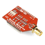
For the telemetry link there is only a WiFly module on the quad ( he is using the wire antenna module, but I strongly recommend the SMA type). Android tablet works in Router mode and WiFly is connected to it as a client.
The app is DroidPlanner, and can be downloaded on google play. For more info you can check the following blog posts:
When it comes to the controversial unmanned aircraft known as drones, business is booming. That could mean scores of new jobs for San Diego, but privacy defenders say courting the drone industry could cost us our civil liberties.
Imagining swarms of drones hovering over most of Southern California makes a lot of residents uneasy, but that’s exactly what Sean Barr of the San Diego Regional Economic Development Corporation hopes to see.
Barr has been working with a coalition of local defense industry advocates to brand San Diego as the drone capital of the world. To ensure that drone makers put down stakes in San Diego, Barr and his allies are trying to convince the FAA to base a lucrative drone test site here. The range they’re envisioning would be expansive.
An alliance made up of Utah universities and the Governor’s Office of Economic Development is making a bid to turn part of the state into a testing ground for “unmanned aerial systems.” You may know them as drones.
But officials from the Mountain West Unmanned Systems Alliance stress it’s not military drones that would be buzzing around Utah’s airspace if they were awarded the contract from the Federal Aviation Administration. The devices are drones that help people, not blow up villages.
“Think of an aircraft that can fly in [conditions] not safe to be in,” said GOED spokesman Michael Sullivan. “Like fighting a forest fire or going into a fire and seeing what’s going on.”
Marshall Wright, GOED’s director of business development for aerospace and defense industries, said these unmanned aircraft could be used for precision farming such as applying pesticides more efficiently or mapping out urban infrastructure.
Get a head start on the NASA Centennial Challenge's ADS-B requirements by plugging a $20 USB dongle into your drone and tracking nearby aircraft:
Start with an AR.Drone (or other ARM-based amateur drone).
Buy a $30 USB dongle. See the rtl-sdr wiki for recommendations.
Compile and install the dump1090 Mode S/ADS-B decoder software with my easy-to-use cross-compiler setup: ardrone-dump1090-cross-compiler
Plug in the receiver.
And now you're decoding packets:
ADS-B sense-and-avoid is seen as critical to integrating unmanned aircraft into the National Air Space, and this is the beginning of a cheap "sense" solution. Next up: "avoid".
Several people have been asking about the ability of a wing to generate lift when upside down. The answer is yes, an upside down wing will create lift if the angle of attack is high enough. Now being in a rotor configuration further complicates things, but the same principles of physics apply. There is a distributed lift along the wing based on velocity (v) and angle of attack (alpha).
When the sum forces of each wing are added, a single vector is produced for each wing. That vector will determine the stability of the wing (the moment force) and the total lift force generated. It is no different for a flying wing than a spinning rotor, the rotor just has a different load distribution due the the non-linear, radially distributed velocity along the span. These moment diagrams should hold true independent of factor such as wing twist and airfoil discontinuity. At any speed of rotation there will be a combination of left/right alpha which will result in a stable rotation in hover. This also holds true that there is a combination of alphas which will provide a stable rotation at any amount of lift for climb while at any power level. This relationship will most likely not be linear however, which means that as the controller adds power, the ratios of left and right alpha may have to change. this means that the vehicle may not be able to be "trimmed out" to stable but rather adjusted for stability depending on power level.This all sums up to "i may need a computer control system to incorporate a trim coefficient based on power input and collective control, if not a complete gyro stabilization system with a feedback loop. Either way, it can be done, and so help me, it will be.
I have taken a couple measures to help enlarge the stability bucket to try to make a stable VTOL ascent/decent possible with manual controls. I have added a generous dihedral of 12 degrees to help compensate for dis-symmetry in the wing lifts, and I have put the cg in front of the control surfaces for each wing. The wing is structurally very sound, made mostly from carbon fiber, so aero-elacticity should be minimized. To ensure that the design is in the ballpark, I will make a test stand to allow it to rotate at low speeds (below flight rotational speed) in order to inspect for any stability issues before full flight testing.
This complexity begs the question, "why not just use a symmetric airfoil???" Well, the answer is that fine tuning the aircraft for improved performance is what takes it from proof of concept, to a viable tool. I have been getting emails about an Air Hogs toy called a Switchblade. It is pretty much the same concept, but without any of the elegance or performance. The old saying, you can make a washing machine fly if you put a big enough motor on it comes to mind. Air hogs is known for making some really cool, really fun, really unique, and really low cost toys. Although the Switchblade meets all those standards, it doesn't fly very well, or for very long. It would not make the cut for a military or even commercial UAV system, and from the ratings I've seen online, it didn't sell very well as a toy either.
At the end of the day, creative people will always try to push the limit. Some people will be neigh-sayers and rant about how an idea will never work, and other will be inspired, and take the technology to the next level. I'd rather be the later than the former. Besides, people aren't remembered for being dismissive and correct, they are remembered for breaking convention and proving the "dismissers" wrong.
Thank you all for your comments and advice. Keep 'em coming!
Posted by Alan Sanchez on April 2, 2013 at 10:27am
We are still growing fast at 3D Robotics. We are looking to expand our engineering team here in San Diego and are looking for a Mechanical Engineer to join us. You can see our other job listings at the company blog here.
Mechanical Engineer
Responsibilities
You will be responsible for contributing to the design, development, manufacturing and testing of new products for 3D Robotics. You will use your engineering expertise and design thinking to create functional and aesthetically pleasing products while working as an integral member of a multi-disciplinary team at 3D Robotics. You will engage with manufacturers, vendors and partners as you work on the development of new products. Because of the wide variety of products we design you will likely design for a wide variety of manufacturing processes (injection molding, metal extrusion, CNC milling, composite fabrication, etc)
Qualifications
BS in Mechanical/Aerospace Engineering or equivalent.
Minimum of 2 years of relevant working experience.
Proficiency in CAD solid modeling and finite element analysis. (Proficiency in Autodesk Inventor is a plus)
Mechanical Design experience.
Product development and manufacturing experience.
Attention to detail and commitment to quality.
Capable of working in a multidisciplinary team environment.
Excellent verbal and written communication skills.
Computer proficiency.
Electrical and electronics experience is a plus.
Familiarity with 3D Robotics products is a plus.
How to apply
Please submit your cover letter, resume, portfolio and any additional material to jobs@3drobotics.com.
I would like to propose you to see this video. It was a sunny afternoon, but especially windy, and i was doing my test flights after the PIDs were done for the MultiWii tricopter. On the video you see training of Kite-surfers who allowed me to film. Aerial and ground shootings were made with ¨Extreme cam " 720p 60ips. Then i played in editing software to slowdown some portions of the footages. the final result : 720p 30ips. I didn't have FPV to lock the video framing and the Tricopter was almost 50 meters away from me. I wanted to show sail actions from the sky and on the ground all the efforts in controlling the sails.
After having a really successful second meet where all those that attempted, were able to plan and fly autonomously, this meet was meant for photography and the cube challenge. However, the weather seemed to have other ideas, with some severe wind. However, it was still a great opportunity to meet up, fly in the gorgeous sun, see what's happening and have some fun. (:
The next meet is being planned now, so check out the Melbourne group if you're interested in attending.
Also, I will be heading to Adelaide over the ANZAC long weekend with my quad so if anyone is around and willing to catch up, please let me know. (:
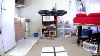
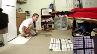
The copter flies away & returns to the starting point at 2 different altitudes, using only optical flow odometry for position & sonar for altitude. The fact that it landed at nearly the takeoff position was probably coincidence, but optical flow has proven very accurate in a 30 second hover. It may depend more on time than movement.
For the 1st time in many years, the entire autopilot was on board. Only configuration parameters are still stored on the ground station.
The takeoff is hard coded for a certain battery charge. This battery may have put out a lot more than the battery it was hard coded for, causing it to bounce during the takeoff. Nothing optical flow guided besides the AR Drone has been shown doing autonomous takeoffs & landings. It takes a lot of magic.
It was a lot more stable than the ground based camera. Ground based vision had a hard time seeing the angle of movement, relative to the copter. Optical flow has precise X & Y detection in copter frame.
How long can they stay in bounds? The mini AR Drone did surprisingly well, compared to the commercially successful AR Drone. The degradation was reasonable for a camera with 1/3 the resolution & 2/3 the frame rate. It's not likely to get more accurate. The mane problem is glitches in the Maxbotix.
Optical flow can hover for around 90 seconds at 0.5m before slipping off the floor pattern. Above 1m, it slips off after 1 minute. At 1.5m, it slips off after 30 seconds. The Maxbotix falls apart at 1.5m over posterboard.
The mane requirement in optical flow is the angular motion needs to be very accurately eliminated or it won't work at all. Using the IMU gyros works well. This is done by adjusting a 2nd pair of gyro scale values until rotating the camera doesn't produce a position change.
The heading & altitude need to be factored in when integrating optical flow or it won't accurately calculate position. The academic way to convert pixels to ground distance involves a tan of the pixel shift to compensate for parallax, then multiply by the altitude. The pixels are so small, the parallax was neglected & the pixel shift was just multiplied by altitude.
Optical flow initially needs to be tested on something like this:
To gain enough confidence & calibrate it enough to start integrating it on this:
A lot of energy went into finding the optimum floor pattern.
So the optimum pattern seems to be random splotches of paint with dry brushing in a grid. Too much brushing makes it too smooth. A few gallons of toner would be nice. A laser printer could get the optimum fractal pattern perfect.
For all the energy going into making robots navigate human environments, there's no pondering of the idea of making human environments navigable for robots. Floors with optical flow patterns would be a lot easier than LIDAR.
Straight lines of featureless tape were the worst. It seems to rely on texture of the paint up close, while painted patterns far away. The only way to get a pattern big enough to fill the flying area with enough reflection for sonar is paint on a plastic drop cloth.
The worst patterns require a higher minimum motion. The best patterns cause the least minimum motion to be detected. The pattern affects the outcome more than the frame rate or resolution.
Long & boring video documenting interference between wifi & the Maxbotix MB1043, the world's most temperamental sensor. Some orientations do better than others. The Maxbotix & wifi wouldn't be very useful on any smaller vehicle.
A totally random orientation of wire & dongle was required. Wire orientation, wire insulation, dongle orientation, dongle distance all determined whether the Maxbotix died. Any slight movement of the wire breaks it.
The automatic takeoff & altitude hold were extremely accurate. The 10Hz update rate wasn't as problematic as feared.
So basically, after 6 years, the Maxbotix still has to be powered up facing away from the ground or it returns bogus values. This continues to be the greatest scourge of sonar navigation. The Parallax sensor in the AR Drone initializes properly with no clearance.
It still needs an external RC filter to filter the power supply. You'd think they would have found a way to store the calibration data on the flash or make a bigger board with integrated power filter to generate the best readings.
The Maxbotix still requires a manual trigger to range at its maximum rate of 10Hz, but it repeats the same value if triggered at less than 25Hz. It needs to be triggered at 50Hz to output 10Hz of unique data.
Flying it manually with the tablet is reasonably easy.
The mini AR Drone has an MPU9150 read at 1100Hz for the gyros, 125Hz for the accelerometers & mag. The PWM is 2000Hz. The IMU needs liberal foam padding or the attitude readout drifts too fast.
It turns out USB host on the STM32F407 interferes with I2C, so you can't read the IMU when wifi is on. It has nothing to do with RF interference. The IMU has to be driven off a secondary microprocessor & the data forwarded on a UART. It needed a 400khz UART to transfer the readings fast enough.
There's at least 0.5ms of extra delay to get the readings from the I2C breakout processor to the mane processor. The I2C interface itself has at least 0.4ms of delay to get the voltage from the gyro. In total, it could take 1ms for a motion to be detected. Such is the sacrifice of reading out an IMU on I2C. The delays from movement to digital reading are what make instability. It's not unlike the AR Drone, which has a second microprocessor read the I2C sensors.
The electronics with wifi use 300mA. Wifi sends 2 megabits, manely consisting of the optical flow preview video. Star grounding & star power supply were required for anything to work. Having everything except the motors behind a 3.3V regulator & 1000uF of capacitance was required.
Wifi was especially sensitive to voltage glitches, making running on a 4.2V battery with lousy MIC5205 regulators extra hard. The MIC5353 would be a much better experience.
After years of dicking around with charge pumps, pullup resistors, & BJT's to turn on MOSFETs that require 5V to turn on, finally got around to probing the Syma X1's board. It uses a MOSFET that turns on at 2.5V, the 9926A. The 9926A is an extremely popular dual MOSFET made by many manufacturers.
The electronics weigh around the same as a PX4Flow, except using the PX4Flow would have required another board in addition to it. The PX4flow was ruled out because of the weight & the size being too big to fit anywhere.
PX4Flow weight: 17.5g
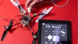
With the PX4Flow connected to USB & Qgroundcontrol fired up on a Mac, it was immediately clear that it had a very long, sharp, macro lens, allowing it to resolve texture from far away.
Setting it to low light mode produced a noisier image. In any mode, the position updates came in at 100Hz, despite the sensor capturing 200Hz.
It didn't need any calibration. Just connect it & it outputs Mavlink position packets. The lens was already focused. It outputs packets at 100Hz on USART 3 but not USART2. It seems to run as low as 3.3V at 120mA. Below that, current drops & LEDs start going out. Above that until the 5V maximum, current is constant.
Most of what the PX4Flow does was redone on a new board, with the TCM8230. The autopilot was implemented on the same chip. The optical flow only does single pixel accuracy, 42fps. It crops to get a similar narrow field of view. It scans a 96x96 area instead of the PX4flow's 64x64. The scan radius is 8 pixels instead of the PX4flow's 4.
It requires a more detailed surface than the PX4Flow. The optimum combination of camera contrast, motion distance, frame rate, & scan radius dictated the camera run at 320x240. Running a higher frame rate or resolution made the camera less sensitive & blurrier in the X direction.
Also, the PX4flow uses a histogram of the motion vectors. Found better results from a straight average of the motion vectors.
Assembly language made an incremental improvement in the scanning speed, but the mane limitation still seemed to be memory access. The scanning area & scan radius would probably have to be slightly smaller in C.
The Goog couldn't find any examples of vectored thumb inline assembly, so it was a matter of trial & error. The STM32F4 programming manual, inline assembler cookbook, & STM32 Discovery firmware are your biggest allies in this part of the adventure.
It turns out there are no NEON instructions in thumb mode. Thumb mode has yet another set of vectored instructions with no special name.
For the 1st time ever, it's the inline assembly language absolute difference of an 8x8 macroblock:
Now DroidPlanner has USB support for the 3DR telemetry board. The new app (v0.5.0) will be on Google Play shortly.
To use the app just install via Google Play, or the attached APK file (if Google Play has not updated yet). And connect the 3DRobotics telemetry module to your device. Open the app and click on Connect. You may receive a notification to enable access to the USB device from android, I this case just press OK.
Users utilizing the TCP connection will need to access their settings and change the connection type to TCP, USB is the apps default now.
As always if you want to help consider donating for the project by buying this app, joining the development team, or reporting a issue/bug/improvement on GitHub.
Just finished trimming and sanding my newly fabricated landing gear.
As best as I can tell these things are incredibly strong, and as they are made of fiberglass quite shock resistant and incredibly forgiving to sheering force. These are for my 10lb aluminum H style A/V Quad that is almost done. The weight makes the thing incredibly stable with regard to video.The entire process from mold fabrication to final touches took about a day and a half, all that's left is spray painting them, but that should only take a couple of minutes.
Some quick notes:
18 plys that degrade in size at two inches per layer so that the thickest point is at the top where the maximum level of bending potential will be.
(3 full length plys first and last; for finish and delamination protection)
Since people have been talking about building nice shock resistant landing gear on the cheap and quickly I thought I would post my solution; and a tutorial on how to build some of your own.
As you can see the mold can be tailored to make 3 - 4 landing gear at once, and really just depends on how much raw material you end up having.
As of now I hope to have the complete tutorial out by about the fourth, I hope it will help some of you guys out though I realize that most of you are more than familiar with the process.
Ever had the need, or perhaps uncontrollable urge, to monitor and control your personal aquatic mammal using an iPad or iPhone? Then the latest fork of ArduPilot is what you need: WalriPilot.
Using WalriPilot, you can* have your personal aquatic mammal:
Roll Over
Swim to the Surface
Regurgitate Fish
These are just some of the base features, so check back for more exciting updates!
The OQ-2 was a simple aircraft, powered by a two-cylinder two-cycle piston engine, providing 6 horsepower (4.5 kW) and driving two contra-rotating propellers. The RC control system was built by Bendix. Launch was from a conventional runway, and recovery was either by returning to the runway or by parachute.
The OQ-2 led to a series of similar but improved variants, with the OQ-3 / TDD-2 and OQ-14 / TDD-3 produced in quantity. A number of other target drones were built by Radioplane and competing companies during the war, most of which never got beyond prototype stage, which accounts for the gaps in the designation sequence between "OQ-3" and "OQ-14".
After WW2 ended various experiment were done with Radioplane target drones. In one experiment in 1950 a derivative of the QQ-3 Radioplane drone was used to lay military communication wire.
During the war Radioplane manufactured nearly fifteen thousand drones. The company was bought by Northrop in 1952.
In yet another example of non-military application of drones, NASA researchers investigate the gases in a volcanic plume in Costa Rica with small electric-powered planes. These planes are, in fact, repurposed military drones being applied to the benefit of mankind.
The full story, with maps, graphics, and more photos is at: