All Posts (14049)

Sort by

News drone attacked by swarm of... drones

9dcfc00103e918586c1c5e3025e05ab42c98ecfb2a43cdd99f4efc5714cf50a8

CBS12 News Crew Attacked By Bees During Palm Beach Mall Demolition Report:

It all started when CBS12 News operations manager Carl Pugliese launched a drone camera to get an aerial shot of a backhoe taking the old Sears apart. The drone is a large dinner-plate sized device with four helicopter-like rotors and two cameras, all operated by remote control via iPhone or iPad.

About a minute into the flight, you can see the assault begin. First one attacker zips by the camera. Then another. Then the whole swarm.

Pugliese said the drone began having trouble flying, but he wasn't sure why. At the same time, he says a "strange bug" kept pestering him, getting in his hair and buzzing him. Meanwhile, Pugliese was able to maneuver the drone closer so he could see what was wrong with it. Bad move.

Angry bees became a cloud around the drone and also began attacking Pugliese and CBS12 cameraman Chad Ellison, whom Pugliese captured dancing and swatting frantically to avoid being stung. Didn't help. Both of them took several stings. Pugliese himself can be seen toward the end of the drone video, diving into his SUV to avoid the swarm. Unfortunately for him some tagged along inside, and he is seen trying to fling them out. He landed the drone from inside the car.

The drone took several stings as well, with the stingers still embedded in its foam fuselage. The whole thing was covered in what Pugliese termed "bee goo."

Read more…
Developer

Android Ground Controller, alpha release

IMG_20130119_221016.jpg

Hi ya'll,

So I started off by writing some software to have an arduplane fly in formation with a human piloted hang-glider.   I still plan to finish this project, but I noticed there was a lack of an Android ground controller for Mavlink/Arduplane.  Since much of the code I was writing for my formation flying project was in Scala, it was pretty easy for me to make it into a ground controller for Android.  Most of the work was in getting USB host mode to work talking to the FTDI part in the 3dr telemetry module.

I've just completed a very early alpha release.  The code is up on github.  You'll need a phone/tablet running Android 3.1 or later with USB host mode support - most 'high end' phones have this feature.  

You'll also need one of these (or similar):

The initial release just provides a basic map,mode display/control, and mavlink log capture.  This early version is up on the Google Play Store as a free application.  If you have success running it, please post here.  If you find failure and tragedy, please post a bug on github (and mention it here if you wish). 

For the latest updates on this fast changing project or to comment, please see the following thread. (No blog moderation delay)

Comments/Questions?

Above is a (crummy photo) of it talking to my Bixler in my living room...

And a screenshot...

3689498812?profile=original

Read more…
3D Robotics

New jobs at 3D Robotics

3689485855?profile=originalWe're growing fast at 3D Robotics. In addition to embedded programmer and electrical engineering positions in San Diego, we have the new position of Editorial Director, working out of the 3D Robotics North offices in Berkeley. As always, you can see our jobs listings at the company blog here

New Job: Editorial Director

Reporting to the Vice President (VP) of Sales and Marketing, the Editorial Director will set and guide the strategy and creation of all internal and external communications, website content, and public relations messages to consistently articulate the mission of 3D Robotics. 

The Editorial Director will also work closely with a senior peer group within the organization as the communications partner on a variety of strategic initiatives. This job is in the Berkeley, CA offices of 3D Robotics. You must be a US citizen or have a US work visa to qualify.  

Responsibilities

  • Develop, implement, and evaluate the annual communications plan across the 3D Robotics landscape
  • Lead the generation of online content that engages audience segments and leads to measurable action. Decide who, where, and when to disseminate
  • Put communications vehicles in place to create momentum and awareness as well as to test the effectiveness of communications activities
  • Manage the development, distribution, and maintenance of all print and electronic collateral including, but not limited to, newsletters, brochures, and 3D Robotics websites
  • Coordinate webpage maintenance—ensure that new and consistent information (article links, stories, and events) is posted regularly
  • Track and measure the level of engagement within the network over time
  • Manage development, distribution, and maintenance of all print and electronic collateral including, but not limited to, newsletters, brochures, annual report, e-newsletters, and 3D Robotics website
  • Manage all media contacts

Qualifications

3D Robotics is seeking an accomplished Editorial Director who has at least 7 years of communications experience, ideally in an “in-house” leadership role within a complex, fast-paced environment.  Familiarity and passion for 3D Robotics products is of paramount importance.  The ability to take knowledge and transform it into exciting and useful messages, and disseminate it to the right audiences through the best distribution channels is critical as well.

  • Highly collaborative style; experience developing and implementing communications strategies
  • Excellent English writing/editing and verbal communication skills
  • A strong track record as an implementer who thrives on managing a variety of key initiatives concurrently
  • Relationship builder with the flexibility and finesse to “manage by influence”
  • High energy, maturity, and leadership with the ability to serve as a unifying force and to position communications discussions at both the strategic and tactical levels
  • Sincere commitment to work collaboratively with all constituent groups, including staff, board members, volunteers and other supporters
  • Self-starter, able to work independently, and entrepreneurial; enjoys creating and implementing new initiatives

Please send applications, with CV, to jobs@3drobotics.com

Read more…
3D Robotics

Writing the rules for domestic drone use

3689499166?profile=originalFrom a New York Public Radio podcast:

Drones are smaller, cheaper, and easier to use than ever, and their cameras are more powerful than ever.

In the near future, drones may be used to find criminals, track wildlife, or find a lost hiker in a remote canyon. They could also be used to look in places where we're not used to prying eyes.

Law professor Gregory McNeal studies the legalities of drone use at Pepperdine University in California. McNeal believes local government, not the courts, should lead the way in writing the rules in the drone era.

He says our notions of privacy may differ from what the law says. McNeal told David Sommerstein the Supreme Court has upheld the right of law enforcement to look for wrongdoing from a helicopter or plane.

***

So if you're tanning in your back yard, and you think that people shouldn't be looking at you, and helicopters are flying over looking down at you, and in that helicopter is someone with binoculars or a high-powered camera taking photos of you, you have no protected privacy right as a constitutional matter against that. Whether it's the paparazzi, whether it's the average guy who decided to go for a flight in a helicopter or a Cessna, or whether it's law enforcement.

But let's say that maybe we don't like that state of the world. Maybe the ground we might want to chart there is that law enforcement can't look onto private property, using an unmanned system, without probable cause.

Are there efforts to do that in Congress?

That's exactly the effort of the privacy lobby. The problem with that view is that every day, police officers get in vehicles and drive around and look at things without any suspicion or probable cause.

They drive their vehicle, they look at you as they drive by, sometimes they wave, sometimes they just give you that look and you worry you're going to get a speeding ticket, and so to say that unmanned systems could only be used when law enforcement has reasonable suspicion to believe that someone is engaged in a crime would mean that the systems would sit idle and never be used.

What kinds of bills are on the move in Congress?

There's a fascinating number of bills that are working their way through Congress…maybe 16 or 20 different bills. The most interesting dimension of it is that there's an alliance between people that we'd think of as progressive or liberals on the left, and Tea Party Republicans, not the fiscal sort of side of Tea Party Republicans, but the fear of government, limited government side [of that], so people like Rand Paul, for example, to try and prevent the use of unmanned systems, almost entirely, or creating such restrictions on their use that the systems would almost not be able to be used at all.

In my view, I think that those are overprotective, I actually think that the better proposal [is] requirements to, let's take the courts out of it, but let's have high levels of transparency on the uses of these systems.

If you're concerned about what your local police department is doing, don't turn to your congressperson in D.C., turn to your city council. So if you're the city of Watertown, NY, and you're concerned that your police department has decided to get a small unmanned system that their patrol officers will be able to launch and sort of fly over neighborhoods and whatnot, the best control mechanism is to go to your city council and say, 'if you're going to use these systems, what are the criteria by which you're using them, let's make some rules. Let's say we want an audit report published on the city's web site that says how many times the systems were used, and what the law enforcement purpose was, and we want to create a citizen review board, just like when we review zoning matters, we want a citizen review board that will also review the use of these systems.'

I think the big problem there is that a lot of people trust their governments, even their local governments, even less than they trust judges.

I think that's right, but I think that's misplaced. Trusting the people to push back and protect privacy is much better than a secret proceeding, where the police officers go behind closed doors to a judge to get a warrant and then conduct their surveillance, and only if someone's rights are violated, only then do the people get, and it's only the person who's individual right is violated, only then does that individual have a right to fight back or push back against law enforcement.

(via We Robots)

Read more…
Developer

px4fmuv1.6_top.png?w=400The PX4 autopilot is an amazing open source platform for research. It is one of the first open source autopilots capable of running an on-board extended kalman filter and other advanced control and navigation algorithms. It is also mass produced by 3D Robotics and very affordable.

Hardware Accelerated Extended Kalman Filter

Recently I have completed a C++ matrix library wrapper around the CMSIS digital signal processing library. This means we can now type matrix math like this:


// continuous covariance prediction
P = P + (F * P + P * F.transpose() + G * V * G.transpose()) * dt;

// attitude correction
Vector y = zAtt - zAttHat; // residual
Matrix S = HAtt * P * HAtt.transpose() + RAttAdjust; // residual covariance
Matrix K = P * HAtt.transpose() * S.inverse();
Vector xCorrect = K * y;
P = P - K * HAtt * P;

// attitude fault detection
float beta = y.dot(S.inverse() * y);

// position correction
Matrix S = HPos * P * HPos.transpose() + RPos; // residual covariance
Matrix K = P * HPos.transpose() * S.inverse();
Vector xCorrect = K * y;
P = P - K * HPos * P;

// position fault detection
float beta = y.dot(S.inverse() * y);

Not only is this very easy to read (similar to Matlab/ScicosLab), it is also hardware accelerated! Thanks to the CMSIS library, multiple floating point operations are executed in one CPU cycle. The result is running a 9 state, 9 measurement discrete time extended kalman filter only consumes 20% of the ARM cortex M4 processor.

You can see the entire example here.

Sensor Level HIL

In order to develop and test the EKF I also developed the capability for full sensor-level hardware-in-the-loop testing. Simulated sensor data is sent from the flight simulator directly to the autopilot. This means you can run a very high fidelity UAV simulation while sitting at your desk.

You can see the python script to run PX4 hardware in the loop here.

Object Oriented Control Library

For those that have followed my development, you know that I am a big fan of object-oriented code. While developing the fixed-wing autopilot, I also created a new control library that has a similar feel to what I wrote for ArduPilotOne. This makes it easy for control engineers and the like , who are familiar with block diagram control systems, to easily translate their ideas to code.

You can see an example here for fixed wing.

The features above are just some that I have recently contributed. There are many developers working on PX4 from around the world and many new developments happening every day! Soon a very powerful optical flow board will be released! I hope that you will join this great community!

Read more…

The winter landscape in Holland!

The last couple of days (weeks) it was snowing now and then. Thus the hole winter landscape of holland was covered in a nice white carpet of snow. A good time to test the UAV of the ATMOS Team from TU Delft.

Sit back and enjoy the combination of a relaxing tune and the nice bird's-eye view over a snowy landscape!

It is also nice to know that in februari this Team (5-8 students of Aerospace Engineering) exist one year so check out the first video on their channel and see their improvements!

Read more…

Receiver Handling and Signal Lost Detection Explained

KK2 Board Connections

How to Measure PWM Signal of RX

As discussed in the user guide, HefnyCopter2 accepts two RX to be connected in parallel, the Primary RX is the RX2, and the secondary one is RX1. That means RX2 should be always available to enable Arming.


Because of this large number of input channels "9 channels"  Primary: THR,ALI,ELV,RUD,AUX  Secondary: THE,ALI,ELE,RUD input ports are reorganized.

This is translated to the following ports:


Ports Definition of RX2   Ports Definition of RX1


RX2 interrupts are all handled by PCINT2 except AUX that is handked by PCINT1 PortB-0


Now lets go through the code lines and check these technique:

Filename: Receiver.c


 Interrupt PCINT2


The primary RX signal is received by PCINT2 "PortC" pins 0,1,5,7 for Picth,Yaw,Roll,Coll respectivly. The interrupt is triggered when there is any change i.e. rising edge or falling edge on any of those pins.

Because of the nature of the RX you cannot get two concurrent rising edges, Because the data is originally sent as serial, each decoded signal is translated into a PWM on a certain channel on the RX and this does happen in parallel, so you get the rising edge of a channel then the falling edge then the rising edge of the next one and so on.

receiver code 2

The above code is replicated with each channel, first we check of there is change on a given pin, in this case the pitch pin. Then we check if it is a rising edge? if yes then we tack a snap shot of the 16-bit timer TCNT1 into RX-raw[1][RXChannel_ELE]

if no which is a falling edge, then we calculate the difference between TCNT1 now and the one stored in RX-raw[1][RXChannel_ELE]. The logic is implemented in CalculateSignalLength2 (RXChannel_ELE).


How to Detect that RX Signal is Lost


The below code shows how HefnyCopter can  detect the following status:

- TX is never detected..... no signal.

- TX was on and now it is off.


Based on the behavior of OrangeRx CH6 receiver it has the following behavior:


case1: When turning-on the RX and the TX is still off, you can detect PWM signals in all channels except THR.

receiver code 8 signals
 

The green signal is for the ALE and the red is for THR.


case2: If you turn on both RX & TX and wait for bind with RX then turn TX off again the THR signal will be the only valid signal. Please note here that THR value is not the one that was detecmined by THR stick in TX, that is why if you turn your TX while your quadcopter ius armed motors will spin and it may fly randomly. 


receiver code 9 signals TXTurnedOff

We can see from the above graph the red signal for THR is on and ELE green is off. this is what we get from RX channels when we turn off TX after being connected with RX.


The below code are very similar to the Picth code, infact the are identical in parts that measure PWM signal, the only difference is in the two lines in the falling edge condition in the "else" block of the "if".

The code saves a timestamp of when last time this signal was received, it uses TCNT1_X which is a 16-bit variable that ticks one time every TCNT1 overflow, which is a 16-bit timer.

Signal Lost Detection


  Clearing bit 5 in RX_Good means that RX can sense a signal i.e. is now connected to TX.


 The next snippet is used to detect when the TX is turned off.


  Signal Loss Detection


We clear bit 6 in RX_Good variable  which means that the TX signal exists. Please note that we can choose any other channel such as pitch, AUX or Rudder. It happens that we have selected ROLL here. So we use the THR with any other channel to make the function.


The below function is regularl called by the main loop to apply actions required by the pilot. Each time the function is called it makes sure that there is updates in RXn_LastValidSignal_timestamp otherwise it sets bits 5 & 6 for RX2 & bits 1 & 2 for RX1.


 Signal Lost Detection


if you want more information about the hardware you may find this link "What is Inside Spektrum DX7 Receiver" useful.

Read more…
3D Robotics

3689499045?profile=originalFrom Hackaday:

There’s a special type of satisfaction that comes from really understanding how something works at the end of a reverse engineering project. This grid above is the culmination of [Spencer's] effort to reverse engineer the IR protocol of a Propel ExecuHeli indoor helicopter toy.

The first thing he looked at was the three different controller channels which can be selected to allow multiple helicopters to be used in the same area. [Spencer] was surprised that they all used the same carrier frequency. The secret must be in the coded packets so his next challenge was to figure out how the data was being transmitted via the Infrared signal. It turns out the packets are using pulse-length coding (we were unfamiliar with this protocol but you can read a bit more about it here). The last piece of the puzzle was to capture packets produced by each unique change of the control module. With each bit (except for bit 11) accounted for he can now format his own codes for a controller replacement. Perhaps he’s looking to make the helicopter autonomous?

Read more…

3689498983?profile=original

Here is an ordered list of my actions to see how I can get my Xbee running on APM2.5.

Xbee is Xbee Pro 2.4ghz S1, Firmware is  XBP24 version 10EC, all defaults except baud = 57600

-Unzipped brand new APM 2.5 from plastic packaging, looks good!
-Cannot see the board version from the black protective cover
-Connected to the windows laptop via USB
-Mission planner v1.2.30 mav 1.0, APm shows up as COM24, baud 115200
-Upload firmware Arduplane v2.68 form Missionplanner
-Upload done, connecting to Missionplanner via same port(COM24, baud 115200)
-Connect done, Hud shows correct attitude

-Disconnect Mission Planner, Disconnect USB
-Board is now powered off
-Two Xbees, S1 Pro, transparent mode, baud rate 57600, communication verified on laptop(Docklight)
-Connected 1 Xbee to the telemetry port shown on the APM2.5 board(Telem. port on black Protective cover, UART0/2 on the board, TX-RX, RX-TX, 5v-5v, Grd-Grd)
-Powered the board with the adapter provided (JP1 is still not connected)
-Board powers on, leds blink(gyro calibration led dance), xbee powers on
-Connect Mission planner with groundstation Xbee COM port, baud 57600, TIME OUT, not connected.
-Verified that no data is coming on groundstation xbee using Docklight
-Board Power off
-Connected FTDI (TX-tX, RX-RX, Grd-Grd)
-Powered the board with the adapter provided (JP1 is still not connected)
-Connected Mission Planner, FTDI COM port, baud 57600, CONNECTED!
-Connect done, Hud shows correct attitude

Conclusion, correct MAVlink data comes to the UART0/2 port but is somehow NOT WORKING with Xbee.
---------------------------------------------------------------------------------------------------

-Removed Black Protective cover of APM2.5
-Soldered pins in UART0 & UART2 available on the side of APM2.5 (v2.5.1, now that i can see it)
-Connected Xbee on UART0
-Powered the board with the adapter
-Connect Mission planner with groundstation Xbee COM port, baud 57600, CONNECTED!
-Connect done, Hud shows correct attitude

Conclusion, correct MAVlink data comes to the UART0 port and WORKS with Xbee.
-------------------------------------------------------------------------------

In search of UART2 for telemetry
-Board Power off, Xbee disconnected
-Cut the two wires connecting the upper pads of AUTOMUX, soldered both the lower two ones.
-Short tested to verify the solder connection.
-Connected Xbee on UART0/2 port on APM (TX-RX, RX-TX, 5v-5v, Grd-Grd)
-Powered using the provided Adapter
-Board On, leds dancing, Xbee powered
-Connect Mission planner with groundstation Xbee COM port, baud 57600, TIME OUT, not connected.
-Verified that no data is coming on groundstation xbee using Docklight
-Board Power off
-Connected FTDI (TX-TX, RX-RX, Grd-Grd)
-Powered the board with the adapter provided (JP1 is still not connected),Board On, leds dancing
-Connected Mission Planner, FTDI COM port, baud 57600, TIME OUT, not connected.
-Verified that no data is coming to UART0/2 using Docklight

Conclusion, no data comes to the UART0/2 port with AUTOMUX upper ports disconnected and lower ports connected(stock Arduplanev2.68 firmware).
--------------------------------------------------------------------------------------------------------------------------------------------

-Connected Xbee on UART2
-Verified No data coming on UART2 port as well.

-Connected Xbee on UART0
-Connect Mission planner with groundstation Xbee COM port, baud 57600, CONNECTED!
-Connect done, Hud shows correct attitude

-Connected USB on USB port, Xbee on UART0
-Powered using USB
-Does NOT CONNECT with Xbee on UART0
-CONNECTS with USB after 30 seconds, but the 'Connecting MAVlink' window does not disappear, disappears only after i disconnect the Xbee

Conclusion, With stock Arduplane v2.68 firmware, with AUTOMUX upper ports disconnected and lower ports connected, No data comes to UART0/2
port, No data comes to UART2 port, correct MAVlink data comes to UART0 port, Xbee connects on UART0 port, but, with USB connected, Missionplanner
only connects with USB, no UART0.
---------------------------------

Meddling with the Arduplane v2.68 firmware

-Downloaded the 'modified' Arduino 1.0.3 software and Arduplane v2.68 from APM google code page
-Created a sketchbook with Arduplane Libraries folder and Arduplane folder
-Set the sketchbook folder as default in Arduino firmware
-Open the sketch, Arduplane.INO
-Select Tools, Board, Atmega2560
-Compile, compiles ok.
-Paste this in APM_Config.h

// use this to enable telemetry on UART2. This is used
// when you have setup the solder bridge on an APM2 to enable UART2
#define TELEMETRY_UART2 ENABLED

-Save, Compile and Upload through USB
-Successfully Uploaded.

Now,
-Disconnect and Reconnect the USB
-Board on(Red LED Alive), no calibration Dancing LEDs!
-Connect Missionplanner using USB COM port
-Starts connecting, Getting parameters, STOPS in the middle of getting parameters!, hangs and then connection FAILED! (Multiple attempts, same results!)
-Random'ish data comes on port UART0 and UART2 at very low data rate. The only LED on is the Red ALive LED.

Conclusion, with firmware modified to TELEMETRY_UART2 ENABLED, with AUTOMUX upper ports disconnected and lower ports connected, Mission Planner stops connecting
on USB port, random data on UART0 and UART2 port. Additionally, abnormal LED behaviour. (So revert back to standard firmware)
-----------------------------------------------------------------------------------------------------------------------------

Major setback: Just enabling #define TELEMETRY_UART2 ENABLED in arduino seems to be stopping proper telemetry everywhere!


So, long story short, can anybody tell how to enable telemetry on UART2 on APM2.5 ?

Read more…

UAVs in the news

3689499075?profile=original

Here are two news stories from the training exercise I helped conduct last week in south Texas.  We were training the Texas A&M personnel on how to operate as the ground crew for the UAV system they purchased last year.  They did a great job and it was fun week working with them all week despite the colder than normal temperatures that we had to deal with.  So congratulations to TAMU-CC on successfully completing their first training exercise with their RS-16 UAV system!  Looking forward to more flying in the future!

Corpus Christi News Cast

Brownsville Newscast


Aircraft System:  RS-16

Wingspan: 13 foot

Length: 7 foot

Weight: 70lbs during these flights and 85lbs max gross

Engine: four stroke 57cc gasoline engine

Autopilot: Cloud Cap Piccolo

Payload: Multispectral HD camera system (HD-EO, IR, and UV)


(BTW: I am the one in the black hat and grey pants acting as external pilot for these flights.)


Read more…


Yesterday I took my new 3DR hexa outside for the first time. Weather was nice and sunny with brisk -7°c temperature. Even though everything worked well when testing, I immediately ran into problems outside. After connecting the battery all of the ESCs started beeping rapidly (two times per second) and refused to spin the motors. I took the hexa inside for a while to warm up for a while and the problem went away and everything seemed to work fine. Unfortunately as we all know, the assumption is the mother of all fuck ups.
I hovered the hexa, but each time I tried to land motors sped up suddenly and the whole thing flipped over faster than I could react. After breaking two props I started investigating further. There was a couple of helpful threads, one offering working solution to calibrate ESC at low temperature.
What I think what happened is this: Pwm value that ESC reads from APM changes a little with temperature. If we assume that lowest value in room temperature would be 1000, in -7 degrees it could be say 990. Now during calibration esc has saved value 1000 as the smallest possible value. When it reads value 990 at cold startup, it decides it’s not a valid value and refuses to start and starts to beep as a warning.
The real danger is in situation where ESC has started successfully, but the temperature goes down. At low throttle pwm value goes under the min limit and ESC turns off as a safety measure. Since not all ESCs do this at the same time, what happens during the flight is that APM tries to compensate this with other motors resulting an immediate flip.
Working solution seems to be to calibrate the ESCs at the lowest temperature you are going to fly. After doing that I had no problem flying outside. I think this would be important thing to mention in the wiki.

Read more…
Distributor

3689499025?profile=original

Video link below:  (and yes it's in French...) 

Radio Canada / Decouverte - Drones are in Canada

They scare a bit the audience but they do a fair job informing too.  From military / civil and hobby drones they cast the net wide. They also explain the good side for saving lives, detecting forest fires and more.  

Good job Radio Canada (Just wish they had contacted me for an interview! hehehe) 

Dany
http://www.CanadaDrones.com

Read more…
Moderator

s-482.JPG

Monday - day heavy, as you know. So long as any work starts on Monday. So I have - apart from today started sheathing wings.
The technology is as old as aviation. Or perhaps older, is not competent.
First the pattern.

On pattern ply cut, mark up, skins and throw wet.

s-484.JPG

And we go to dinner. And after dinner with various gums, tapes and other improvised equipment fix ply to the frame of the wing. And leave to dry for tomorrow...

s-483.JPG

Read more…

A few tips for the APM Mission Planner

Having learned the hard way on a few things, I thought I'd put together a little video that shows some tips and tricks with the APM mission planner.
The first time I tried mission planning some things were a mystery, like how do you actually get into auto mode to fly a mission? I found something that looked like a way to do it from the APM software flight data tab, but that turned out to be a disaster because there was no way to get it out of auto mode and my quad went crazy and crashed into my house. Second fun one was when the mission started but didn't finish, so I had to trudge across 60 acres of mud to retrieve my quad. Lastly I almost lost my quad on a mission that went awry, for some unknown reason it did 2 way points, then took off in the wrong direction, into the fog.  I tried to take back control, but I couldn't see it in the fog, then soon after I couldn't hear it either.  Then the sinking feeling came over me, $600 down the tubes! But fortunately I remembered to setup a safety switch that would return to home. I flipped  the switch and waited for what seemed like forever, then that wonderful sound of buzzing bees emerged out of the fog and my quad flew itself back home.  Phew!!  Learn these tips and tricks by watching this video, it could save you some money.

Read more…
Moderator

VirtualRobotix at Modena Makers Italy

3689498885?profile=original

In these months Virtual Robotix community present in italy our Drone tecnology , this week was in Modena and present VRBrain and last revision of Arducopter32 rev 2.9 .

In our stand we had a lot of peoples for two days and we was more success also respect of presentation of 3d printer :)


At these link can you see the presentation of VirtualRobotix at Modena Makers this week 19-20 January 2013

http://www.virtualrobotix.com/photo/albums/modena-makers

And last Presentation of 2012 at Makers Italy :

http://www.virtualrobotix.com/photo/albums/makers-italy-i-corsi-di-virtualrobotix-com


Our target is traver around Italy first and then the other country in europe to enroll new developer and present the great work doing by developer of our community .

The new Arducopter 8-32 bit firmware have a lot of great new functionality and is incredible that all this work is Opensource , when we explain this concept to the peoples that we meet in these events thy are very surprise.

Congratulation TEAM :) We are doing great work !!!

Best

Roberto


Read more…

Another GCS for UAVs

3689498927?profile=original

I have been wanting to share this for sometime and seeing as several people lately have been posting about GCS ideas, I figured I would post a little about mine to give them some ideas. Above is an image of the GCS I had developed for control over some UAV projects I had worked on for my thesis/dissertation and work on in my free/hobby time.

The callout boxes are pretty much self explanatory. The battery (I fly with primary and accessory battery with larger aircraft thus 2) and flight timer indicators are 7segment displays, and the scrolling status box at the top is a 16x2 character LCD. The touchscreen on the right is neat as I have 4 different modes in it which will turn the GCS off, display numeric attitude values, GPS map, or the artificial horizon indicator (as pictured) which is similar to the one in the APM. The radios on top are two 900 Mhz antennas (one for video or one for data) and if FPV is desired over 900, a 433Mhz radio can be plugged into a spare USB port.

Most of the data transmission I do for my work however takes place over 5.8 Ubiquiti radios that some of my local DIY friends had recommended to me. They provide a very elegant solution to frequency conflicts and allow higher bandwidth than the current serial limited radios and only require I hook up the ethernet port of this GCS and network switch. But I digress.

The groundstation has a large internal laptop supply to handle AC input, or can be directly powered through DC terminals if out at the field. From there, custom power circuits clean the power to twelve and five volts and distribute it out through the internals of the system. Also, internally it contains several microprocessors to handle the messaging to the seven segments displays, touch screens, and interfaces with the buttons and joysticks that relay the information to the internal computer for further processing.

Lastly, the nice solution of this is that the internal computer acts as a TCP/UDP server for several groundstations. An APM or my custom control systems (AIRSIDE) connect to the ground station through a radio (serial or ethernet), which the data then becomes parsed and distributed through UDP multicast messages to the peripherals on the groundside. Then, a primary ground station software (whether the APM mission planner or my control interface (as pictured on main screen)) connects to the distributing server program through TCP. Essentially allowing for the downlink to be split into multicast UDP messages for everyone who is interested, but only allowing for uplink/downlink to one primary GCS software via TCP. Thus peripheral information can be displayed as long as you follow MAVLINK protocol. Most of the software internal to the GCS has been written in C++ or LabVIEW.

Anyway, if anyone has questions, would like me elaborate on something, or provide a comms/power diagram; Please post and I will answer when I can. Hopefully this gives everyone else who is still debating on what to include on their groundstation ideas on what a final solution could look/work like.

Read more…

Trying out 2.9 on a windy day.

I had it up and down about 10 minutes yesterday, it was pretty windy so I was mainly just putting it up, trying loiter, then RTL over and over.  I take video with an old deactivated iPhone 4 and it usually does really well, I don't know what was up with the horizontal lines yesterday.

Also note the bad bearing on #4 motor when it spins down, It's been like that since new but I guess I'll replace it soon.


Read more…

January 18th, 2013


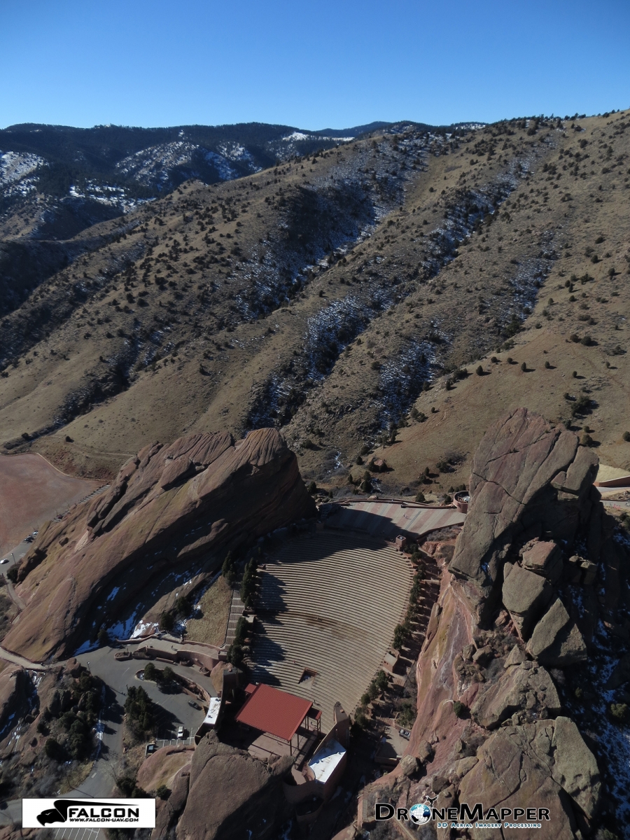
Amazing day in Colorado for a photogrammetry mission with Falcon UAV over Red Rocks Amphitheater. At 6,450 feet above sea level, Red Rocks Park is a unique transitional zone where the Great Plains meet the Rocky Mountains. Red Rocks Amphitheatre is a geological phenomenon – the only naturally-occurring, acoustically perfect amphitheatre in the world. Some of the rock formations in Red Rocks slope as much as 90 degrees, while others tilt backwards. The southern monolith, that bears resemblance to a ship, is named "Ship Rock." On the opposite side of the Amphitheatre stands "Creation Rock." Both of the monoliths are taller than Niagara Falls, and the Red Rocks Amphitheatre was once listed as among the Seven Wonders of the World.

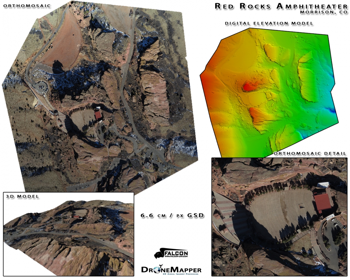
Falcon flew late morning of January 18, 2013 and collected more than 600 photos in a little over 30 minutes. We shot a combination of nadir looking and oblique photos. One of the obliques, shown above looking to the west - southwest, gives the viewer a feel of the scale of the two monoliths that frame the amphitheatre. The nadir images were processed at a resolution of 6.6 cm and the resultant geo-referenced orthomosaic, digital elevation model and 3-D model are also shown below. If you are interested in learning more on how to precisely map difficult terrain please do not hesitate to contact either falcon-uav.com or dronemapper.com


Read more…