Rise of the Drones airing again on PBS/NOVA, January 23, 2013 at 9:00 PM eastern.
Preview can be seen HERE.
Rise of the Drones airing again on PBS/NOVA, January 23, 2013 at 9:00 PM eastern.
Preview can be seen HERE.
Hi all,
I thought I would attempt to draw up a couple of diagrams of the PID loop in the ArduCopter 2.9 release.
Alt Hold Controller
What we are trying to do with this controller is remove the need for the different stages of altitude changing that was in there before. This controller can handle both the altitude hold function as well as the fast altitude changes. We have tested it up to 5 m/s. This lets us do the very fast reduction in altitude I think you were asking for. It also does this with very little overshoot.
We use the square root of distance relationship to slow the airframe at reasonable accelerations to remove the very large accelerations that a linear distance vs velocity relationship applied. We took this one step further by combining the linear relation P loop with the square root relationship. This provides a smooth transition between the two modes in both acceleration and velocity.
The linear distance calculation is the distance that the square root relationship needs to be moved in order for the linear velocity relationship to be a tangent to the square root velocity relationship. This provides a step free transition between the two at the linear distance x 2. Acceleration of the two curves is also equal at this distance meaning that the motors don't pulse as we swap between the two curves.
The graph below is for the default Alt Hold parameters.
The 250 cm/s/s is the maximum acceleration that will be required of the copter while still allowing the copter to stop without overshoot. The copter will not reach these accelerations unless it is instructed to travel over approximately 125 cm/s. This shouldn't happen during Alt Hold but can happen during Altitude changes. This limit was chosen because it should be achievable for all reasonably designed copters. To not be capable of this acceleration the copter would have a cruise throttle of over 700.
Using this controller you can still move the requested altitude slowly however if we need to stop or change direction it is able to still follow that request. In fact, the controller is not limited in the acceleration it can ask for. In an emergency this controller will be able to do it in less than 1 second and 2.5m. (I realize these are simple calculations and this situation only occurs if the user asks for stupid things).
We now have different speed limits for up and down but currently they are set to the same thing. We did this because the controller can now handle much faster rates so we didn't think we needed to limit it to such small values going down. I assume this was done for safety.
The final thing I should mention is the design of the controller with respect to the pid loops. This is a (P/sqrt) -> PD -> PI (Position -> Velocity -> Acceleration) controller by default. However, there may be advantages to using (P/sqrt) -> PD -> PID with correct filtering.
So why no I term in position. This is because the I terms in these loops will reduce the following error when using this controller with a moving set point. The current design of the controller ensures that the distance between the moving altitude request and the current altitude is enough for the controller to stop the aircraft in that distance without accelerating beyond 250 cm/s/s. This is how we achieve such a small overshoot from very fast decent rates. This is also why we don't use an I term in the Velocity controller, we don't want overshoots due to I term build up.
The other parameter that is critical in this function is the velocity D term. This has the effect of minimizing the error between the requested velocity and the desired velocity during deceleration. This is set as large as it can be without noticing any jerkiness or oscillation during altitude changes.
I hope this helps people understand how a number of these control loops work.
Enjoy,
Leonard
Thanks to the Dev team for getting ACv2.9 to us, especially as it fixes a lot of features that have been broken for a while. This one in particular is one that I had been trying to get to work - http://diydrones.com/forum/topics/automated-parachute-drop.
The mission was to takeoff to 2m altitude, fly to WP2 @ 25m alt, drop the chute, fly to WP4 to a) stay out of the chutes way and b) not yaw towards home hopefully to capture the chute while it fell with the 808 #16v2 keychain camera attached to one 'copter foot, then descend to WP5 @ 5m and land.
Some of the flight was a little wobbly as I had adjusted a few PID settings yesterday while experimenting with something else. Below is how the mission looked. The setup was followed as per the camera control wiki page > shutter configuration - http://code.google.com/p/arducopter/wiki/AC2_Camera. A simple 5 gram servo released a rubber band holding the chute underneath the 'copter.
I had to change the nav speed to 2m/s because the waypoint was very close to the takeoff point and that was still too fast as the 'copter had reached the waypoint before the 25m altitude had been reached.
Waypoint radius was set to 1m and I had turned AUTO_VELZ_MAX to 150cm/s from 125cm/s but that also made the takeoff very/too rapid.
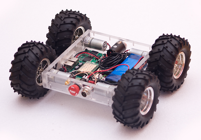
I hope it will be interesting to see new open design of wifi rover. It is controlled from Android application
Having seen a vast improvement in the Arducopter handling when vibration was reduced I decided to experiment further. I thought it was worth trying to soft mount the tubes so cobbled together a test frame on a bit of 4x2. The 12mm tube mounts are held in place with ‘o’ rings. The video is with standard 75 shore rings 17mm ID. This was just the first test so was quite pleased but will experiment with other types/sizes.
This method will probably only work on a ‘H’ frame where the motor lift balances out.
As Gary Mortimer noted, the forthcoming Parrot AR.Drone GPS add-on, which was announced at CES, supports MAVLink and can work with QGroundControl and the APM Mission Planner. I talked to Parrot at CES, and it sounds like they're going to leave autonomy to hackers and third-parties; the official AR.Drone software will support GPS datalogging, but not control, itself. They also haven't announced a price or release date for the GPS/datalogging module yet.
But for us in the MAVLink world, this is great news. There are now 500,000 AR.Drones out there, and the possibility for them to become real drones, with autonomy, could lead to a huge surge of people getting into amateur UAVs.
RCTimer Voltage & Current Sensor (http://www.rctimer.com/index.php?gOo=goods_details.dwt&goodsid=861&productname=) it is now available (i have ordered one). I have one AttoPilot Voltage and Current Sense Breakout - 90A from Sparkfun (https://www.sparkfun.com/products/9028). I would like to test both with my APM 2.0 when i have enought time to ironing the wires and XT60 connectors.
I think that sell an APM Power Module with XT60 Connectors (http://store.diydrones.com/APM_Power_Module_p/br-apmpwr.htm) compatible with APM 2.0 and previous versions could be good for 3DRobotic. I don't understand why 3DRobotics does not have think in backwards compatibility, they are loosing buyers that have to go to Sparkfun or now to RCTimer.
 The first parts for my UxV control station prototype have arrived and the planning and drafting is making progress. Thanks to a few friendly companies, much faster than I feared it would. Unfortunately, some major parts are still on the way, so I can't really start building yet. I'm using the time to work on the drafts and the functions, thinking of new ideas, kicking old ideas out. And of course, already testing some ideas on the Arduino Mega. The repository at GitHub is already created - although nothing is in it yet.
Here's an overview about the feature ideas. The full list and a few more infos are on the features-page on my website.
New ideas and comments are very welcome!
https://www.youtube.com/watch?v=HZLZJC6_Vfg
Last post I presented this homemade hexacopter. This is primarily a mechanical steadycam style motion compensation/smoothing system, the 2 servos (roll, pitch) engage and act as dampers to reduce oscillation and alter the "home" position to compensate for hexacopter pitch and roll. Then that whole system is rubber band isolated from the motors/airframe to reduce high frequency vibration. (Thanks George for this definition).
Main flight controller is APM2.5. Servos are controlled by other FC, CRIUS SE v1.0 running Multiwii. I did program a new FC mode named STEADYCAM which is different from GIMBAL mode. This new mode uses the PID loop + delta angle to alter the "home position" in order to compensate both non-desired gimbal movements and hexacopter pitch/roll. Note that the STEADYCAM mode is not for regular gimbals. I will upload my code to Multiwii repo soon.
There is no way I can use a bigger FC for this purpose. Why? because the FC goes attached to the Steadycam arm, not the hexaframe, so It has to be an independent FC (I recommend CRIUS Lite which is even cheaper, because no barometer is needed here)
Here are a couple of videos (One moved up by mod.):
https://www.youtube.com/watch?v=G6Zr1axUutk
More work has to be done. I have to play a bit more with Steadycam PID values and delta angle proportionals. But so far I have a smooth video after some post edition stab.
The concept of this design is based on ECILOP, but with Argentinian flavour. Also this Steadycam don't have GYROs just a cheap FC with a PID loop, which is more configurable and extensible.
Next: Outdoor footage, Add Rx pitch/roll input to Steadycam, Improve stab.
Well I feel better now. I'm always a little nervous to fly a new ship until the first crash. You never know how she'll deal with adversity.
I was flying FPV in loiter at ~15m when it suddenly pulled hard right and back making a nice arc into the ground at about 20kph according to the telemetry log. The current jumped from the ~30A normal to over 60A in the few seconds of the death plunge. When I got there the motors were spinning and wouldn't react to transmitter commands including disarm. All the props were broken of course.
Looked through the logs a bit, but I can't tell what happened. If anybody cares to take a glance and give me some insight, I would be very grateful. I don't mind when things go terrible if I can at least understand why it happened.
The damage seems to be limited to a couple of cracked arms and a few other frame bits. The GoPro was fine thanks to the waterproof housing. Not even a broken antenna on the 3dr radio or video Tx! I'm taking it all apart tonight and checking the electronics, they got covered in snow, but no physical damage that I can see so far. I'll upload some pics once Iphoto stops crashing every time I try to get them off my camera. There must be weird solar weather or something going on today, I've never had a problem getting pics off of my camera before, really strange...
I'll have to upload my tlogs from the windows machine, just a minute.
: )
Team-blacksheep have very nice frame for DJI-NAZA with some fancy PDB, but I don't have NAZA and I wanted some modification to mount APM2/2.5, so here is my version of that frame, no fancy PDB and PCBs, just black fiberglass :)
If you do have DJI NAZA go get that frame right NOW !
APM2.0 with 90° pins fits under the top plate with analog and telemetry pins exposed.
APM2.5 with ublox GPS.
Set the LED_MODE parameter to 9, It will slow blink when disarmed, solid armed, fast blink + beep on low battery.
The CG and the APM location moved a little bit, but it can fly as regular X quad. (don't pull back too much)
I just changed the AP_MotorsQuad.cpp X frame set-up to:
add_motor(AP_MOTORS_MOT_1, 55, AP_MOTORS_MATRIX_MOTOR_CCW, AP_MOTORS_MOT_2, 1);
add_motor(AP_MOTORS_MOT_2, -125, AP_MOTORS_MATRIX_MOTOR_CCW, AP_MOTORS_MOT_1, 3);
add_motor(AP_MOTORS_MOT_3, -55, AP_MOTORS_MATRIX_MOTOR_CW, AP_MOTORS_MOT_4, 4);
add_motor(AP_MOTORS_MOT_4, 125, AP_MOTORS_MATRIX_MOTOR_CW, AP_MOTORS_MOT_3, 2);
Setup
Motors: Tiger MS2212-13 980KV
ESC: jDrones 18A (Flashed with SimonK FW)
I really like the 10X5 Graupner e-props (or new Carbon 10X5 e-props) with 4S 3000mah lipo, after some fine-tuning its very sharp fly.
Here some raw clips from Arducopter 2.8.1 tuning flights:
BTW Jani from jDrones (that where I CNC all my custom frames ;) ) has put together fancy RTF kit, so check that one out.
EDIT:
The top outside hols for the arms are ~0.5mm off, I think so chek it before cuting.
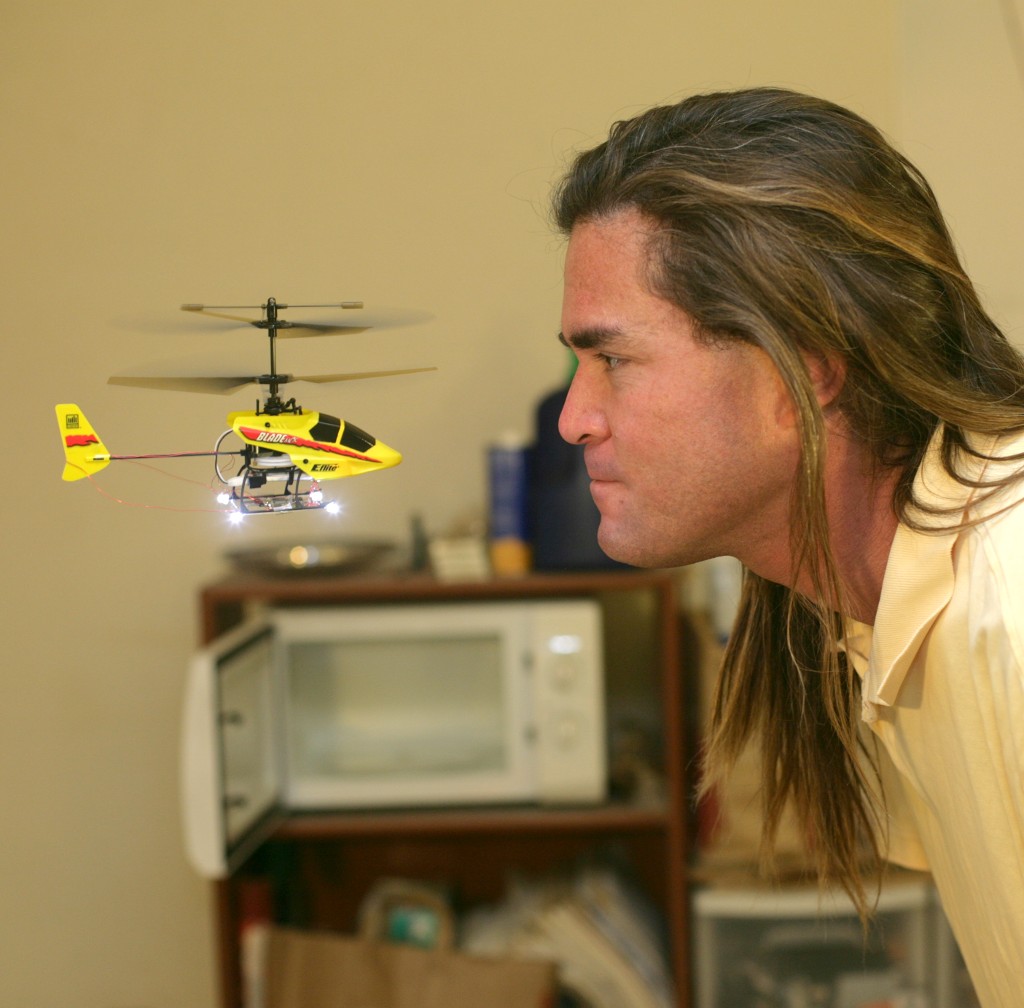
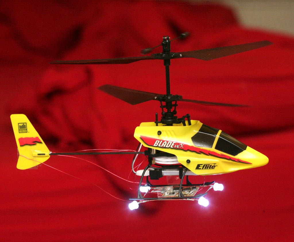
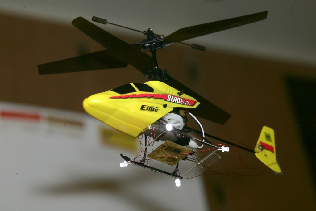

The Blade MCX being the most stable indoor flying thing ever invented buys most of the precision, but it still took some doing to get vision, sensors, & feedback good enough to keep it in the smallest box. The Blade MCX is 4 years old, but it had just the right combination of cyclic, flybar, & servos to be more stable than anything since.
The IMUs since then haven't achieved the same motion damping of the mechanical flybar. It's a mystery why the Blade CX2 wasn't as stable.
Got the last of the features on the tablet which were last done on the RC transmitter, years ago. Manely manual position control in autopilot mode. Rediscovered the ages old problem where velocity & direction can't be changed if a move is already in progress. It would have to stop moving & recalculate a new starting position of a new line to fly.
The algorithm was all part of a plan to make it fly in straight lines. Merely setting fixed velocities didn't make it fly in a straight line. It would need a much larger flying area for changing velocity to be practical. The war on straight lines was a long battle in 2008, comprising many blog posts.


As the tablet interface evolves, it's very confusing, with separate inputs for manual mode & autopilot mode.


The final leap in accuracy came from tapping the Blade MCX's integrated gyro to drastically improve the heading detection without increasing the component count.
Its heading is extremely stable, allowing its position tracking to be more stable than using the magnetometer alone. The improvement costs nothing, but would require more parts on copters with no analog gyro already installed.
That was purely the magnetometer without the gyro.
Another discovery with this system was pointing it 45' left of the cameras during calibration seems to be the optimum alignment for the cyclic phasing.

Entropy
Many years ago, a fake test pilot noted that averaged sensor data produced better flying than lowpass filtered sensor data. Lowpass filtering was the academic way of treating the data because it got rid of aliases.
The fake test pilot also noted that jittery servos produced better flying than perfectly timed servos.
In all these cases, the noisy unfiltered data had less latency than the filtered data & glitching the servo PWM around 50hz conveyed more data than their normal 50Hz update rate allowed. Since there were no data points at an alias frequency & with enough amplitude which could cause the aircraft to oscillate, the reduction in latency was a bigger win than the reduction in noise.

Now a camera system has 2 cameras, each running at 68fps, limited by clockcycles. They're not perfectly timed or synchronized, so an image from either camera is captured at 136 unique points in time. A new position is calculated when each of the 136 frames comes in. This allows slightly faster position updating than if the cameras shot at exactly the same 68 points in time, without requiring more horsepower.

The velocity calculation has only a 1/13 second delay, is pure noise, but gives a much tighter flight.
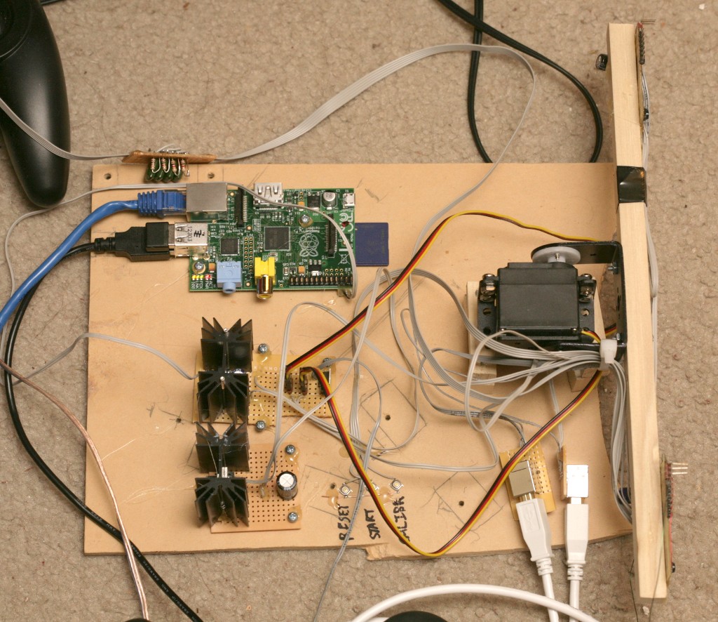
Anyways, the dual 68fps system uses 90% of the raspberry pi with the ground station on. Without the ground station, it uses only 60%. The RLE compression generated by the board cams takes a lot less horsepower to decompress than the JPEG compression from the webcams, but is made up for in the higher framerate.
The dual cameras on a single pan/tilt mount at 320x240 70fps is probably as good as a cost effective system can get. Better results could be had from 640x480 or higher resolution at 70fps. That would take FPGA design & something faster than a raspberry pi. Webcams max out at 640x480 30fps, but higher framerate has proven more important than higher resolution.


As you know the Boeing 787 has been grounded by caught fire on the Li-ion battery.
It looks like Japanese battery may have some issues on this incident:-(
You might reminded some laptop PCs caught fire by its Li-ion battery, few years before.
It is ironic to the restriction of Li-ion batteries for carry on baggage and air cargo.
Our copters will not fly without high power density Li-Po.
How do you treat your Li-Po battery and deposit after some failure ?

The OSD (On Screen Display) is an instrument that provides the pilot with navigation information helping him to conduct a safe and conscious FPV (First Person View) flight. The information are imposed on an image from on-board camera, giving more control over the RC model and facilitating safe return to base.
OSD displays all key information about model:
OSD with autopilot it can display additional information about:
With OSD FPV flights are safer. Pilot knows where he is and know way to home even in unknown terrain. The OSD with artificial horizon allow to continue flight in conditions of reduced visibility, for example in the cloud or at night. It also works as user interface for configuring autopilot. It displays menu and allow to choose between many options using included keyboard (locally) or RC channel (remotely).
OSD supports PAL and NTSC standards. The system automatically detects transmission standard from on-board camera and adjusts the information system. In case of loss of the signal from the camera, OSD continues to generate in the video standard in which the camera worked, allowing you to complete the IFR flight according to the instruments
The UAV Autopilot is the safety part of FPV system. It offer IMU based stabilization of the plane in hard conditions, flight through the waypoints and automatic return to base in case of RC link lost. UAV Autopilot offer 3 flying modes activated with free RC channel:
Autopilot offer many mixers to allow wide choice of flying platform. Actually it support settings:
RC Autopilot can be configured using OSD. It displays menus with option to choose. Configuration can be done also in flight. http://www.rcgroups.com/forums/showthread.php?t=1811191
A friend has one but we haven't flown with it yet, looks good though.
Hi all,
Just thought I would share with all that we had the first DIYDrones.com Melbourne group meet last Saturday. Attended by 6 people, with 5 quads and a heli all getting a good fly. It was great to meet everyone and see the variations on a theme with the quads. There was a nasty breeze that gusted quite strong, so flying conditions weren't ideal, but there was still some very good flying by all. Unfortunately there wasn't video of everyone, but I have still managed to pull a short video together of some of the action.
We are planning the next meet for sometime in February (the morning of 10 February is looking to be the date at the moment), with the goal of everyone attending to have a successful FULLY AUTONOMOUS and recorded flight under their belt before they leave.
Of course, all Melbourne people are invited [with more details to be shared through the Melbourne group page] but even if you're in the area from interstate or internationally, please stop on in.
Have a great day and safe flying,
David.
Here is a picture of my little JVC Adixxion, replacement for my malfunctioning GoPro Black.
As you may know I published a BLOG of my experiences and trials and tribulations with the much vaunted GoPro Hero 3 Black.
Finally after much wasted time dealing with the GoPro Company sent it back for a refund I started searching for an alternative camera. I considered both the Sony Sport Cam and this little JVC Adixxion.
The Adixxion seemed much the better camera but was $350.00.
After Christmas I found an incredibly short lived deal for $99.00 and immediately purchased the Adixxion.
The overall experience with this camera for me has been the complete opposite of the experience I had dealing with the GoPro Camera and the GoPro Company.
Namely I am very happy with it.
Likes:
Size and form factor are better than the GoPro and even more so when the GoPro has its case on it.
Has standard mount base screw socket on side and bottom (and picture can be inverted so camera can be used upside down).
Has 1080P 30 fps and 720P 30 and 60 FPS and generally a better picture in daylight than GoPro.
Built in image stabilization definitely decreases multicopter vibration problems. Not in GoPro.
5x digital Zoom works without image degradation on 1080P due to large camera chip. Not in GoPro.
WiFi live preview actually works on IPad and with computer and with negligible delay (less than 1/2 second).
Much easier and more intuitive 6 button menu and navigation than 2 button GoPro.
Built in color LCD viewfinder.
Single battery life is better than the GoPro with the additional add on battery.
Nothing malfunctioning at all.
(You do need to do a firmware update from the JVC web site for the WiFi to work properly.
Dislikes (none major to me):
Night time video not as bright as GoPro.
Doesn't have all the fancy super high resolution video modes the Black had (of almost no interest to me anyway).
Although the IPad and PC based WiFi worked much much better than the GoPro, the Adixxion does not currently support direct connection to an Android so my Nexus 7 is not of use to me for WiFi at this time.
Basically a lot more to like than to complain about, really glad I got it.
Haven't tried the WiFi live preview while flying yet, but will report back on the results of that, live preview actually does work well enough to use it for FPV so long as the camera WiFi and the RC signals do not interfere with each other.
GoPro should take a lot of cues from this camera for their future efforts.
If they get the bugs out of the Black it will be a cool camera, but right now, this is a more useful camera to our RC community in almost every way.
Even if you have to pay full price, you won't be unhappy with this camera, but if you can find any kind of deal at all (Amazon currently $250.00) you'll make the GoPro owners envious.
Hello everyone,
I'm starting a new project branch for the ArduPilot, and I hope it will thrive. For an experiment run the DroidPlannerv0.1b.apk file on an Android Tablet (needs android v4) . Here it's a mere screenshot:
I know this it's not the first phone/tablet GCS to show up on this community (for example Bart copter-gcs, this closed-source copy, the Apple GCS by Zachary), but I'm thinking in a different approach. This is what I want to do:
Some great things are helping on this project:
Screenshots:
Before getting into how I think this should evolve let me show to you what I have already done. Bellow is a screenshot of the home screen where the mission planning is made. On the left there is a list of waypoints altitudes, on the center a map with the home position. On the top left a menu to change the screen and on the right some commands relative to this screen.
On the next picture there are show some of the actions on the menu, and more waypoints where added (with a different altitude). Using the "open file" action to open a real flight get's us back to the first picture in the post. (Files are loaded from a folder named waypoints on the sdcard, you can copy files generated with mission planner to this folder)
Edit: I added one more screen to the DroidPlanner App, is the Ground Control Point (GCP) screen. It's function is aid in the positioning of control points on the field for photogrammetry applications.
The operation is simple:
Here is a screenshot of the GCP screen with a KMZ file just loaded.
And this is after some GCP have been placed on the field and have been marked;
How it think it should evolve:
The part I'm procrastinating is the communication interface (mainly because Bart has made it already). I want to implement first a wifi-UDP communication system redirected by some main GCS, this way the development will be easier (the USB port will be free for the programmer) and a nice mobile GCS will be left behind. Next the USB-serial-Xbee communication, I have some working demos to receive data from the serial port but these need more study.
How to develop:
First get a clone from my branch "DroidPlanner_Stable" at this link. Next download the ADT Bundle for the google SDK and eclipse. Download and import the Google Play library into Eclipse as explained here. Now you should be able to import the DroidPlanner project/compile/ and run on a android device (needs Android v4).
Edit: About the USB connection to 3DR radios, some tablets have USB host capabilities and the drivers needed to communicate to a FTDI CDC IC.This means the device can supply power via USB and Acess USB devices, for me all it takes is an USB microB to USB type A cable (like the one in the picture).

To decrease the doubts about this here is a screenshot of my tablet connected to an APM1 board accessing the APM terminal. I used a terminal app called "Android USB Serial Monitor".
As I pointed out at the start there is this file: DroidPlannerv0.1b.apk, that can be run on a android v4 phone or tablet.
Edit: I only have one Chinese 7 inch Tablet, so I don't know how it will behave on other devices but it's worth a try. Some has run the App on a Nexus7. I had some doubts because of the API key need to access Google maps data was a debug one.
About android v2.x.x devices:
Edit: There seams to be a lot of questions about v2 android devices, these will not be supported. At least not on the initial releases. Because with android 2.X there would be some problems with the Google Maps API v2, and the communication drivers (since USB host mode is supported only on version>v3 devices). I know it would be great to support everyone but that is a lot of work. I think at least for the start just focus on android 3.1 or higher. this way we can use the latest version of the maps API and have USB support.
And an android v4 Tablet is very cheap now, and that's what I think should be targeted.
Any questions or suggestions post bellow. Any problems downloading or compiling the source contact me with a message on this post.
Thanks.
--
Arthur Benemann
I've been flying the new Skyhunter made by FPV Model with the APM on board. I figured I'd share the param file since I didn't see it listed in the repository.. I've had many comments that the Skyhunter looks like it's 'hunting' when the APM is in full autonomous mode. I'd love to see what other tweaks the community can do to the parameters and the plane!
On New years Eve I went flying with my Nitro ArduPlane. Mainly to check my config settings since my last attempted flight. This time it went much better. after tweaking my Turnigy 9X it seems to by flying fine. Next up, full Mission!