All Posts (11086)

Sort by

Summer is in full swing and it’s the best time to get into drone hobby! We’ve prepared a great offer for all drone enthusiasts — from today and until the end of the week get advanced drone controller Edge and Raspberry Pi Autopilot board Navio2 with 20% discount!


4thof-july-1.jpg?width=600


To get the discount go to our online store and use coupon code “edge4th” during checkout to save $140 on Edge Kit or “navio4th” to save $34 on Navio2 autopilot. Edge and Navio2 are in stock and ready for worldwide shipping!


Read more…

Hello!

Here is a short video on Dawn, AEIOU's on board AI platform for UAS. I thought some of you might find this interesting.

Dawn runs on a companion computer, and does things like let UAS avoid obstacles, monitor pedestrians, be aware of aircraft and just generally understand their environment. Dawn also has an API and a simulation environment that lets non AI expert developers build apps to support specific types of missions, and train Dawn's deep learning models to detect new things. 

You can learn more about Dawn at www.aeiou.tech

Read more…

GET will showcase its AUVSI Xponential top innovation award winning technology (http://getcorp.com/get-auvsi-xponential-2018-gallery/) at Drone Berlin, September 25 - 26.

Come see us to discover the miracle of wireless powered flight, explore how the GET Air industrial platform revolutionaizes what you can do with drones today, and reserve your pre-order number for free (http://getcorp.com/get-air-turnkey-solution-pre-orders-announcement/)!

If you missed - enjoy two-hours flight video with alternating cycles of wireless charging right in the air (http://getcorp.com/video-of-alternating-cycles-of-wireless-charging/)!

Read more…
Developer


I'm proud to present you a preview of
"Rescue FC", an integrated safety system suitable for unmanned aerial vechles, developed by "Marcopter" and "MRN-Electronic".
The main features of "Rescue FC" are:

• Dual flight control system redundancy management
• Single or Dual RX systems for full redundancy
• Manual or automatic switchover between flight control units
• Integrated flight termination capabilities with automatic parachute management
• Flight control units can be different from each other, or identical (for example two "Pixhawk" with a different firmware version, "Pixhawk" as primary fcu and "DJI" as secondary or viceversa, the combinations are endless)
• SBUS/CPPM R/C compatibility
• Mavlink communication if available on flight control units
• System arming detection with PWM or Mavlink feedback for secure switch
• The flight termination function can be controlled with SBUS/CPPM channels, single or double PWM external signal, dry auxiliary contact
• Self diagnostic functions
• Double power supply channels from 7.4 to 50.4V to increase availability
• Simple and quick configuration with the integrated 0.96” OLED display. No external systems or PC are needed on the field
• Visual and sound alarm of the FC status
• Firmware upgradeable

Hardware for this tests:

• FCU-Primary: "VRBrain V5.1" with "Ardupilot:Copter V3.5.5"
• FCU-Secondary: "CC3D" with "LibrePilot V16.09 R777"

Soon more details, its price will amaze you!

Marco - "Marcopter"
(Ardupilot Dev Team)

Read more…

stereopi_2.jpg?width=600

Hello!
I’d like to share with you the details of our last project on Compute Module 3 for playing with stereo video and OpenCV. It could be interesting for those who study computer vision or make drones and robots (3D FPV).

It works with a stock Raspbian, you only need to put a dtblob.bin file to a boot partition for enabling second camera. It means you can use raspivid, raspistill and other traditional tools for work with pictures and video.

JFYI stereo mode supported in Raspbian from 2014, you can read implementation story on Raspberry forum.

Before diving into the technical details let me show you some real work examples.

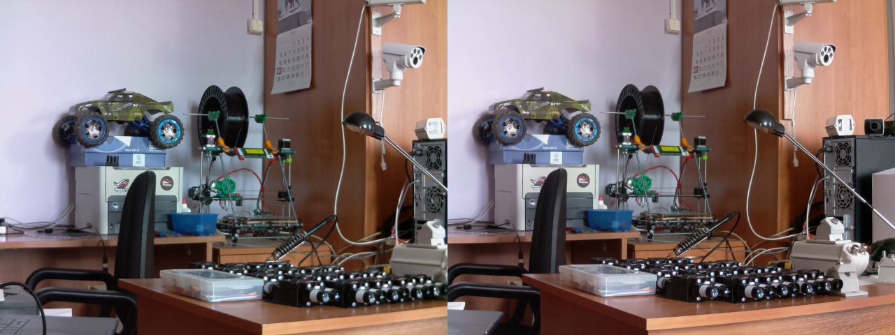
1. Capture image:

raspistill -3d sbs -w 1280 -h 480 -o 1.jpg

and you get this:

photo_1280_480.jpg?width=600
You can download original file here.

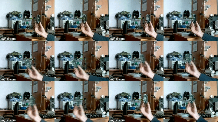
2. Capture video:


raspivid -3d sbs -w 1280 -h 480 -o 1.h264


and you get this:

2buo65.gif?width=600


You can download original captured video fragment (converted to mp4) here.

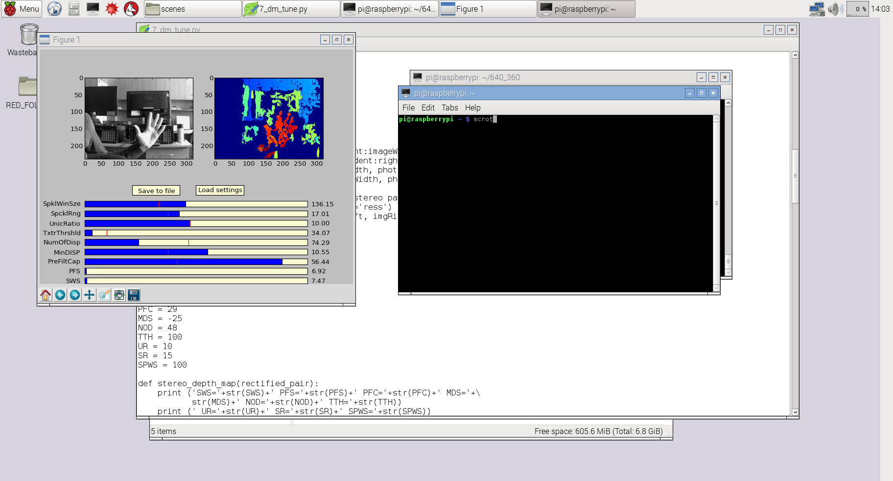
3. Using Python and OpenCV you can experiment with depth map:

2018-06-01-140326_1824x984_scrot.png?width=600

For this example I used slightly modified code from my previous project 3Dberry (https://github.com/realizator/3dberry-turorial)

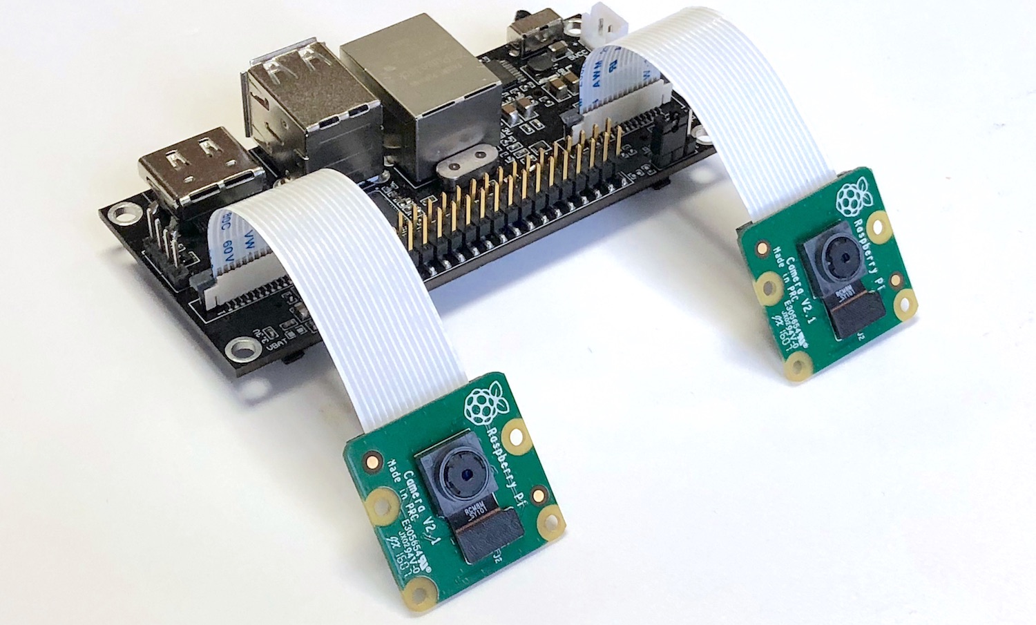
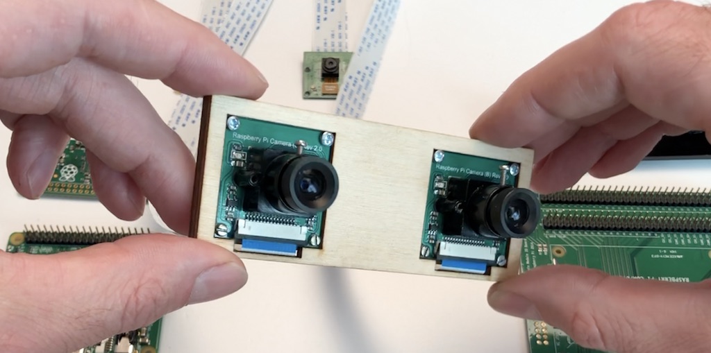
I used this pair of cameras for taking the pictures in examples above:
waveshare_pair.jpg?width=600

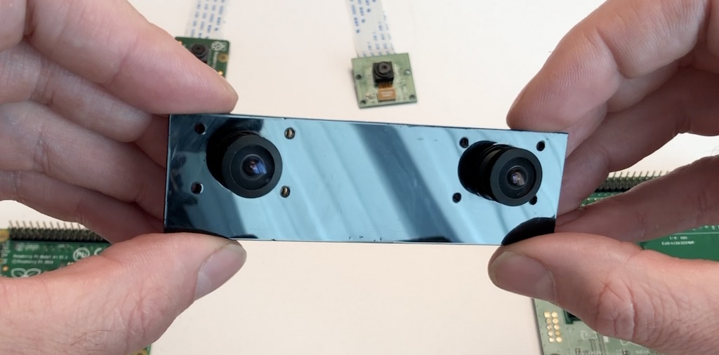
For video livestream from drone I use wide angle (160 degrees) cameras like this:
waveshare_wide_pair.jpg?width=600

Now – to hardware part.

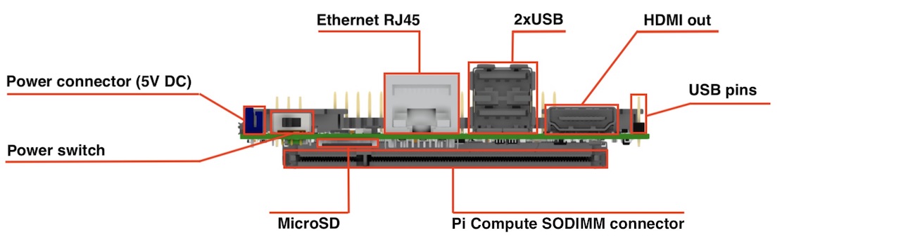
Front view:
stereopi_front_noted_1280.jpg?width=600

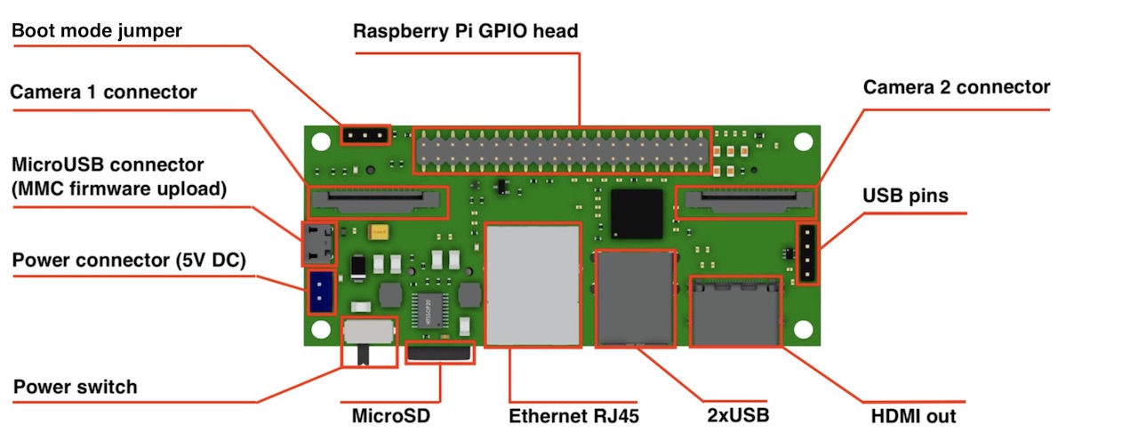
Top view:
stereopi_top_noted_2_1280.jpg?width=600

Dimensions: 90x40 mm
Camera: 2 x CSI 15 lanes cable
GPIO: 40 classic Raspberry PI GPIO
USB: 2 x USB type A, 1 USB on a pins
Ethernet: RJ45
Storage: Micro SD (for CM3 Lite)
Monitor: HDMI out
Power: 5V DC
Supported Raspberry Pi: Raspberry Pi Compute Module 3, Raspberry Pi CM 3 Lite, Raspberry Pi CM 1
Supported cameras: Raspberry Pi camera OV5647, Raspberry Pi camera Sony IMX 237, HDMI In (single mode)
Firmware update: MicroUSB connector
Power switch: Yes! No more connect-disconnect MicroUSB cable for power reboot!
Status: we have fully tested ready-to-production samples

That’s all that I wanted to cover today. If you have any questions I will be glad to answer.

Project website is http://stereopi.com

Read more…

UVify Draco

UVify is a proud member of Dronecode. Draco is the flagship of the UVify lineup.

Draco is the product of sophisticated engineering crossed with a passion for FPV racing drones.

FPV racing is bred from the grassroots straight out of hobby town. Every aspect has been broken down to the bare basics and distilled into a standardized ritual of design and building. From which tape works best in a specific spot, to understanding the minute PID changes required for crisp flight control, the FPV racing community continues to tinker and establish new and creative methods of improvement.

This intricate involvement with the core physics and mechanics of FPV drone racing is what the design team behind Draco use to drive their vision. By utilizing the best available materials with intelligent, rugged design philosophy, and future-proof sensor and electronic systems, Draco reduces countless classic setbacks you would normally find in the field, and provides a platform to move forward with new features and technology. All of this in a package that remains competitive in the FPV racing scene.

While being designed from the ground up and going through dozens of prototype iterations, Draco still includes many key elements which you would find in a standard hobby grade craft. A hobbyist will notice familiar components and layouts that can trigger the creative bug for some interesting design modifications. Also, the removable arms have a six-pin connection opening up a world of vehicular possibilities. The option to add and remove an HD action camera mount ensures that no matter how extreme or what kind of FPV ride you take, you can capture the footage in a format worth sharing.

Key Features:

High Quality Carbon Fiber and Composite Chassis - Durability to protect the sensitive electronics, not cheap plastic.

Interchangeable Arms - Swap out the arms for fast repairs or entirely alter the propulsion system.

Future-Proof Technology - 6s LiPo ready, open ports for additional tech on board.

Professional Vehicular Design - A complete unit with a body at the convergence of practicality and aesthetics.

Smart Batteries - Ruggedly protected Smart Batteries ensure information is available for proper use and safe charging.

Read more…

Drone Training and Consulting Program

Hello Folks, 

I have recently launched a drone training and consulting program; Commercial UAS Developer, and am looking for new clients who need to develop their own custom drones for specific missions, and assistant consultants with significant drone experience and/or B.S. in relevant engineering fields.

This is a 6-week one-on-one training program covering unmanned aircraft design, fabrication, and laboratory & flight-testing. I am a PhD in aerospace engineering and UAS researcher in unmanned aircraft design and testing. For more information and further questions, please check out the Drone Developer site: www.dronedeveloper.org or email me at: victor@dronedeveloper.org. Spread the word around to those who may be interested!

Thank you,

Victor Maldonado

Read more…

Python library for Ardupilot Plane

If you want to connect your companion PC to the latest ArduPlane release, get telemetry data or commanding your custom path planning algorithm, I hope this little library of mine comes in handy.

The class Plane() is basically a wrap around dronekit: it simplifies some variable names and functions and make it easy on SITL to "arm and takeoff". Main functions are:

  • connect() for connecting with the autopilot
  • set_ap_mode() / get_ap_mode() for setting, getting the autopilot flight mode
  • arm_and_takeoff() for arming and takeoff like copter
  • mission_add_takeoff() for quickly adding a takeoff item to your mission
  • set_ground_course() for setting the ground course in Guided mode
  • get_rc_channel() / set_rc_channel()

Find my code on Github

Read more…

Is it Illegal to Drink and Drone?

3689732131?profile=original

Using a drone, whether as a hobby or business project, seems harmless to most people. The reality is that the risks of midair collisions are high. Drone operators cannot see oncoming aircraft and do not have special tools to detect them. Also, the risks increase when the person is intoxicated. It's illegal to drink and drive, but is it illegal to drink and drone? Drone operators should learn more about the official regulations before they step outdoors.

Review Federal Regulations

The Federal Aviation Administration (FAA) sets nationwide rules as to how aircraft are operated in the U.S. airspace. This is necessary to prevent collisions in areas where airplanes fly overhead regularly. These rules include the design, operation and maintenance of aircraft, which includes rockets, kites and balloons. Drones, also known as unmanned aircraft systems (UAS), are the most recent additions to FAA regulations.

There are many rules that affect how drones are flown. Operators cannot fly their machines higher than 500 feet. Those who want to fly drones for business purposes must obtain a certificate. Flying a UAS for fun requires that you register with the agency and adhere to general safety guidelines.

The Alcohol Restriction

The general rule is that drinking while droning is not recommended. People are expected to use common sense when operating a potentially dangerous machine. Alcohol is known to slow a person's reflexes and impair the ability to make sound judgments. If the flyer is intoxicated, the drone becomes a danger to any aircraft who enters the U.S. airspace.

Under Title 14, sections 91.17 and 91.19 of the FAA regulations, commercial drone operators are not allowed to operate under the influence of drugs or alcohol. They cannot fly within eight hours of consuming alcohol or exceed a blood alcohol level of 0.04 or greater. A police officer is allowed to administer a test and send the results to the FAA. If a violation is found, the FAA can terminate or block a person's ability to receive a UAS certificate. There is also the possibility of fines or imprisonment. If you are caught drinking and flying a drone, according to Summit Defense, pilots can be charged with “flying under the influence” or “FUI” and face up to six months in county jail and a $1,000 maximum fine.

The restriction of alcohol while flying a drone means that it is illegal to drink and drone. Federal Aviation Regulations (FARs) are regulated and enforced by the law, so police officers and judges could get involved in an investigation. For all UAS operators, the main goal is to avoid controversy, which means that they should not drink and drone.

Read more…

Precision landing is a critical requirement for a large number of commercial drone applications, be
it autonomous routine patrols for security & surveillance, package delivery at multiple locations,
remote inspections using docking stations or a GPS-denied environment like a warehouse. It is
one of the key components for automating and deploying drone operations at scale.

GPS alone is not accurate, IR beacons get affected by surrounding conditions and require power
on the landing site, RTK-GPS is complex to setup, requires additional infrastructure and it still
does not give the desired results.


FlytBase, the company bringing intelligence and connectivity to the
drones, today announced the release of an automated precision-landing solution, FlytDock- the
world’s smartest visual target landing solution, compatible with the widest range of drones.

3689732139?profile=original

FlytDock enables the drone to precisely align and land itself on the site with a centimeter-level
accuracy. It works across conditions; whether it is landing in day or night, outdoor or indoor
(GPS-denied) environment, on a ground-level or elevated platform, or even on a moving or floating
(in water) platform. Powered by FlytOS, this intelligent plugin utilizes computer vision techniques
and dedicated landing algorithms to precisely align, approach and land the multirotor on a visual
marker on the ground. There is no infrastructure/electronics required on the landing site,
making it easy to deploy at scale. Further, the system can be remotely managed and controlled
over cloud (4G/LTE).

FlytDock is readily compatible with DJI Enterprise, Ardupilot, and PX4 based drones.

To learn more visit https://flytbase.com/flytdock

Read the full blog.

Read more…

Use speech recognition to control a flight

In this video I present the voice recognition feature in my GCS/Companion-app-combo FlightZoomer. The feature allows to control the flight of an RC aircraft (or multicopter) using simple voice commands. In order to get an additional safety level against wrongly recognized commands, the engine does read back whatever sentence it understood. By affirming the readback, the command is then activated. Just check out the video to see how this works.

VoiceFlight.jpg?width=700

On this image you can see the flown route. At point 1 I activated the autopilot (which b.t.w. is a copy of the Boeing 787 autopilot), then I commanded some left turns: first to a western course of 270° (point 2), then south 180° (point 3), then 50° (point 4), 270° again (point 5) followed by a right turn to 50° into the downwind (point 6). At point 7 a descend to 470 meters is initiated. Finally there is a turn to 150° into the base (point 8) and at point 9 the ILS approach is activated. The turn into the final approach (point 10) and the subsequent landing (point 11) was then performed fully automatic.

As you can see on the video, the voice engine really performs nicely and understands my commands well. You can also see how it misunderstands me in once case (and how the misunderstanding is resolved) when I pronounce a number wrongly (I am not a native English speaker).


FlightZoomer is a software solution, that runs on off-the-shelf devices and offers all you need for instrument flight and much more (e.g. a cellular network databus between gcs and companion computer, the companion computer is a smartphone, optional usage of 3rd party radio telemetry, embedding of the FPV camera feed in the cockpit app, synthetic FPV view based on telemetry alone).


The solution runs on top of the Ardupilot stack and will be released shortly. More information on https://flightzoomer.com/

Read more…
Moderator

Preview of Archon Sentinel the autonomous system for inspection of industrial plants developed by Archon.ai.

The system is equipped with a dronestation capable of supporting different types of terrestrial and flying robots.

It's based on edge computing technologies that guarantee continuity of service even in the absence of broadband Internet connection. A remote operator is able to control robots in real time, schedule and schedule inspection missions. The drone station is equipped with GPU power to support third-party apps and I.A. Technologies based on neural networks. We are looking for industrial partners to develop the project if you are interested contact Info@archon.ai 

The drone tecnology is developed around a custom vr brain hardware : arducopter and ardurover firmware. On board we use a companion computer for AI managment functionality based on Neural Network tecnology ...

The control of the drone (rover , copter , quadplane ) could be in blos mode , remotly by a web app .

We are start in europe some test with Enac blos flight. 

This is an example of neural network tecnology used for indoor localization ... a drone station use this tecnology for robot auto docking .

Wer are seraching technology and industrial partner for implement this kind of  tecnology in different market around the world. 

If you need more info contact me at rn@archon.ai

Hope that you like our last development done by virtualrobotix and archon team.

Thanks to Ardupilot team for great work done in last years around our great software :) 

Roberto Navoni

Read more…

Bearingless Rotor - Update

3689732034?profile=original

Test Video

I was finally able to perform a test of the new drive test stand.  The previous test stand used a 4-stroke engine and a less rigid test frame.  This test stand consists of a 6.5 HP, 2-stroke DuraForce engine coupled to a V-Belt centrifugal clutch with a custom made drive shaft.  Couplings between the engine/drive-shaft and drive-shaft/clutch are stainless steel flex-couplings similar to the type used on the Robinson tail rotor shaft drive.  I added a large flywheel to the engine to attenuate the torque pulses from the engine.  The flywheel also makes starting the engine much easier.

The variable pitch mechanism has the following characteristics:

I chose to NOT include a dedicated follower link which forces the upper half of the "swashplate" to follow the speed of the rotor.  Instead, the attachment of the pitch links to the control horn on the rotors has only one degree of freedom, and thus uses the pitch links to transmit torque to the upper (rotating) portion of the swash plate to make it follow the rotor.  I plan to improve this design on my next rotor build, but for proof of concept, this seemed to work reasonably well.  The final product will have 4 blades on each rotor, so I will just need to make sure of proper clearance between the control horn of one rotor, and the flex-element of the neighboring blade.

The lower half of the swashplate is connected to a giant scale servo at only one point.  I was aware that this actuation force, being applied offset from the centerline of the rotor shaft, could induce some binding or sticktion in the variable pitch collective control.  I wanted to test this approach because it so greatly simplifies the connection between the servo and the swashplate.  To combat this tendency to bind, I designed the upper portion of the swashplate as a quite long "sleeve" which slides up and down on the OD of the rotor shaft. 

The "stickiness" issues I experienced during this test I believe are due to the following effects and design choices:

  • The upper swashplate "sleeve" material is 6061 aluminum which has a quite high coefficient of friction with steel.
  • The rotor blades, in their relaxed state, have only a slight pitch angle (3 degrees) but the design pitch is around 15 degrees, so the pitch servo and linkage must overcome the torsion of the 3/8" fiberglass flex-element in order to achieve the design pitch of the rotor blades.
  • Additionally, when operating at design RPM of 1410, this blade induces approx 1600 Lbs of centrifugal force, or tension, on the fiberglass rod flex-element.  This force tends to make the blades want to straighten out, back to their relaxed position, and thereby increases the amount of force/torque required to achieve the design blade pitch.

To mitigate these issues, on the next hub design, I will attempt to:

  • Lengthen the upper sliding section of the swashplate.
  • Use lower friction brass or teflon sleeves as linear bearings.
  • Build the rotors with the blades at flight operating pitch in their relaxed state.
  • Keep the pitch servo attachment to the swashplate as close to the centerline of the rotor shaft as possible.

Another problem encountered during the test was the detection of false triggers from the engine RPM photo-interrupter.

The blue line is the engine RPM and the orange line is the clutch RPM.  You can see all of the high spikes which go off the chart for the engine RPM.  This means I was picking up false triggers on the photo-interrupter input.  My circuit does include Schmitt Triggers on the tachometer signals, which seems to be working well on the other two photo-interrupters, but was getting some noise on the engine tach.  I will have to hook up an oscilloscope to see what the issue is.

FYI, the Grey trace is the rotor RPM (approx 2.8 : 1 reduction from the clutch),

The cyan trace is the pitch servo signal in microseconds (inverted)

The yellow trace is the throttle servo signal in microseconds.

3689732117?profile=original

So while I discovered some issues (engine power, and pitch mechanism stickiness) I had basic success of proving that I could operate a home-made set of rotors, with an internal combustion engine, without excessive vibration.

I would still like to over-speed my rotors to ensure the safety factor ( I used a 4:1 safety factor over the static tensile strength of the flex-element fiberglass rod).  I would like to take the rotor up to 2000 RPM, which would put the tensile force at 3200 Lbs, - double the normal operating force, but still approx 1/2 of the ultimate tensile strength of the material.

Next steps:

  • New carburetor for engine to get the power/RPM I need.
  • Tuned exhaust for engine (again, for power)
  • Run rotor at 2000 RPM to verify strength / safety factor.
  • Add lower friction sleeves to swashplate to reduce binding
  • Tilt rotor at speed to observe gyroscoping effects on vibration.
  • Attempt to control/balance test stand attitude using closed loop control from a gyro. 

 For those who think this is an ill-advised project, please refrain from negative comments.  I readily acknowledge the difficulties that await me down the development road.  I am working this project for my own satisfaction, not for a commercially viable transportation vehicle of the future.  I am enjoying the process and the knowledge and experience I'm gaining at each step of the way.  If you have questions or encouragement, I welcome those comments.

Thanks!


Read more…

Seahawk depth sensing drone

3689732067?profile=original

One of our projects is almost near completion. The Seahawk can autonomously fly and capture depth and temperature reading from bodies of water. It was initially developed to measure the depth of cow manure ponds, but it can obviously be used for more than just that. Soon you will be able to find it on our website. Here are some of its features:

- Transducer Sensor
- Depth Range- 1.6-328ft, 0.5-100m
- Temperature Range- 14-104 degrees Fahrenheit
- Outputs excel files with the date & time, coordinates, depth, and water temperature

*Appearance may differ from final product.

Read more…

Eagle Eye-30IE-50 is a 3-axis high stabilized EO/IR dual sensor gimbal for drone inspection,surveillance,search and rescue applications.
The daylight sensor is from SONY FCB-EV7520,the 30X zoom camera provides 1080P 60FPS full HD video streaming and up to 360X zoom capability,which enable you to see every detail you need in the air even you are far away from the object.While the thermal camera is with 640*480 resolution,25HZ,allows you to detect targets in the night or low visibile conditions,and provides you with priceless information.Furthere more,the thermal camera comes with a 50mm lens,which will enable you to get very clear thermal image even you are 500 meters away from the target.So this EO/IR gimbal is very suitable for long range surveillance and security missions.
High-performance 3-axis gimbal is developed based on FOC(field-oriented control) technology,which will give you crystal clear video footage.

Eagle Eye-30IE-50 is using the most advanced thermal tracking technology,with which you will never lose the object,the tracking function works on daylight sensor too.How it works:zoom in and put the object you want to track in the screen,move the cursor to the object and lock it via controller,and then the camera will track it automatically.

Another big feature for Eagle Eye-30IE-50 is that the gimbal will geotag the video streaming and photos,also gimbal Yaw/Pitch angle,height,time information will be displayed on camera OSD,this is really important when you are conducting missions like rescue and search.

Eagle Eye-30IE-50 comes with an amazing advantage that the gimbal can not only be controlled via PWM signal,but also serial command.Also gimbal status(like Yaw/Pitch/Roll angle,zoom position etc) can be obtained by sending serial command to the gimbal via its serial port,which is really useful for precise gimbal control and system integration.

Eagle Eye-30IE-50 provides an outstanding wiring hub design for RC receiver and video output port,which makes wiring pretty easily.Also the gimbal offers 2 smart speed modes:FAST speed and LOW speed.Fast speed mode is used for small zooming range,which makes the gimbal control sensitive and quick.LOW speed mode is used for large zoom range,will enable you to target the object more accurately

Feature

1) Weight:1200grams(cameras included)
2) 1/2.8 inch 2.13MP CMOS sensor
3) 30X optical zoom,1080P/60 HDMI output for video downlink
4) 1080P/30 H.264 video recorded for on-board TF card
5) Thermal camera:640*480,25HZ,50mm lens,1X/3X digital zoom
6) Auto object tracking function
7) Geotagging,gimbal Yaw/Pitch angle info,height,time will be displayed
8) PWM control and serial command control
9) Convenient wiring hub for RC receiver and video output
10) 3-aixs high stabilized gimbal system
11) Adjustable control speed: SLOW speed for large zoom range,accurate.FAST speed
for small zoom range,sensitive and quick.
12) One key back to home position

Product link

http://www.yangdaonline.com/eagle-eye-30ie-50-30x-eo-ir-gimbal-with-50mm-lens-with-object-tracking-and-geotagging/

Product photos

3689731857?profile=original3689731981?profile=original3689731935?profile=original3689731994?profile=original3689731870?profile=original3689731891?profile=original

Read more…
Moderator
 
We derive thrust, roll, and pitch authority from a single propeller and single motor through an underactuated mechanism embedded in the rotor itself.
 
This allows new types of conventionally-capable micro air vehicles which only require two motors for practical control. This contrasts with the many servos and linkages of conventional helicopters or the many drive motors found in quadrotors.
 
Conventional UAV formats applied to smaller and smaller micro air vehicles lead to significant design challenges. A swashplate-controlled coaxial helicopter must find room in its mass, size, and cost budget for four actuators (two big rotor motors, two swashplate servo motors) and a complex linkage assembly. A quadrotor must similarly support four motors and face the practical problems of rapidly shrinking rotors. Our new rotor system provides significant system simplifications while retaining all the advantages of cyclic control.
 
3689731603?profile=original
 
The main motor directly drives the propeller hub, which is itself connected to the propeller blades by two inclined hinges. The hinge geometry couples blade lead-and-lag oscillations to a change in blade pitch. Instead of only driving the motor with a steady torque, we add a sinusoidal component in phase with the rotation of the rotor to induce a cyclic pitch variation. The amplitude and phase of this control signal determines the magnitude and direction of the vehicle response.
 
This paper presents a new concept a MAV propulsion system capable of using a minimum number of actuators in dual rolls. This simplifies and lowers the cost of MAVs. Removing complex swash plates and reducing the number of actuators reduces the number of parts, thus increases reliability (fewer parts to fail), reduces maintenance costs, reduces vehicle mass, and reduces manufacturing costs. Experimental results for the actuator response are presented along with a demonstration of a full flight vehicle using this system for both active stability and maneuvering.
 
 3689731652?profile=original
Conclusion
We have shown that a hinged, underactuated rotor can mimic the behavior of traditional cyclic control systems in small MAVs without requiring either additional servomotor actuators or complex linkage systems. Both the magnitude and response time of the resulting control moments are sufficient for stabilizing and maneuvering a small, 358 g coaxial MAV.
 
In future work, we wish to develop a technique for determining optimal geometric design parameters for power-efficient operation given application constraints on required moments, thrust, and rotor size. This will allow us to evaluate the system-level power efficiency of this technology verses other control strategies while taking into account the associated actuator and structure material weights. The ultimate aim of this technology is to achieve reductions in system complexity and actuator count that may enable future small, simple, and low cost micro air vehicles.


J. Paulos and M. Yim, “An underactuated propeller for attitude control in micro air vehicles,” in Intelligent robots and systems (iros), 2013 ieee/rsj international conference on, Tokyo, Japan, 2013.
Read more…

Job Opportunity - Los Angeles area

Hi Everyone - 

My name is Arnold i'm a technical recruiter here in Southern California. I'm currently working with a client in the San Fernando Valley who is looking to hire someone who has Pixhawk/PX4 experience. This would start off as a contract but could go permanent. Please take a look below. 

Location: San Fernando Valley 

Length: 6 months possibly goes full-time


Product – Our client develops unmanned aerial systems (UAV).

Duties -Our client is looking for a software engineer who does programing and development using pixhawk/px4 software that will be used in a UAV.

Necessary Skills:

-PIXHAWK/PX4 A MUST HAVE
- Embedded Firmware/Drivers
- linux (using NuttX or Raspbian)
- c/c++
- ARM (they are using STM 32 cortex M4)

Desired Skills:
- UAV
- motor control

Please send resumes to: 

Arnold Melgar

arnold_melgar@oxfordcorp.com

818-878-3152

Read more…

many drone applications such as photogrammetry, orthophoto generation, 3D terrain modeling etc require to geotag images. There is some geotagging software but we found them complicated to use.

we developed DroneeGeotagger.

DroneeGeotagger in-browser image geotagging software. it is super simple to use and it works in-browser that means no cloud involved. Your data doesn't go to the internet. it is secure )

DroneeGeotagger geotags 1 image in around 0.5 seconds. 

How does it work?

For DroneePlane users

1. Open the browser and go to DroneeGeotagger

2. connect to DoroneePlane's wifi "Dronee",  it will automatically get GPS coordinates from the drone and will list in the browser.

3. Take images from camera and "drag and drop" inside the DroneeGeotagger. It will list images with at least order

4. Press "Geotag all" button. Geotag will start and geotagged images will be saved on the desktop.

For other drones users

1. Open the browser and go to DroneeGeotagger

2. Drag and drop CSV file inside the DroneeGeotagger.It will list GPS coordinates with at least order.

3. Take images from camera and "drag and drop" inside the DroneeGeotagger. It will list images with at least order

4. Press "Geotag all" button. Geotag will start and geotagged images will be saved on the desktop.

For more information visit our blog

Note: Dronee Geotagger is completely free to use.

To get notified by Dronee's latest news, follow :

Dronee Youtube channel

Dronee facebook page

Cheers,

Tomi

www.dron.ee

Read more…
3D Robotics

Via Hackster.io. From the YouTube description:

The goal of this project was to drop a glider from the edge of space using a high altitude weather balloon. The glider is entirely homemade and uses the opensource Pixhawk flight controller + a Raspberry Pi Zero to disconnect at the desired altitude and fly to a predetermined landing location. There is no direct radio contact with the aircraft, but we included a GPS tracker made for cars in case the glider didn’t make it to the landing site. We tested the glider by first dropping it from a homemade quadcopter. This took 6 test-flights.

Satisfied that everything was working properly, we prepared to launch the glider from the balloon. Although our target was 30km, we only had a few free days to launch, and on every day predictions showed that strong stratospheric winds would blow the glider hundreds of miles into the ocean if we launched from that height. We settled for a 10km launch altitude, and set the Pixhawk to land at a location within 20km of where the predictions estimated it would end up if it simply free-fell from the balloon.

We inflated the balloon, tied the glider to a long string to minimize swinging, and let it go. It was a two hour drive from the launch site to the landing location, and when we got there the glider was sitting on the ground roughly 10m from the target! Max Altitude: 10.048km, 6.243mi Max Speed: 95.5m/s, 212.5mph Time Aloft: 2hrs 8min 18s Dist Traveled: 195.95km, 121.76mi

THE GLIDER: The glider is built from foamcore with coroplast for winglets and control surfaces, and laminated with colored tape for water-proofing. It carries two mobius cameras, two servos, a pixhawk flight controller with GPS, and a separate GPS/GSM tracker. Critically, all the electronics are inside the fuselage, which we packed with handwarmers and sealed shut before the flight to keep anything from freezing. Two 5200mAh 3s batteries provided more than enough power for a two hour flight (we were hoping to fly longer and higher). The takeoff weight was ~1300g.

THE FLIGHT CONTROL: We used a Pixhawk for flight control. A Raspberry pi zero is connected to the pixhawk via USB and communicates with the Pixhawk using the Mavlink protocol. A simple python script on the Pi sets the flight mode on the Pixhawk to MANUAL on startup to prevent the servos from moving and wasting the battery during ascent. The script continuously checks the altitude, and when it reaches the target, triggers a solid state relay to burn a short piece of nickel-chromium wire, disconnecting the glider from the balloon. The script then sets the flight mode to AUTO, so the Pixhawk will direct the glider to a single target waypoint. Source code: https://github.com/IzzyBrand/spaceplane

THE BALLOON: The ballon is an old military surplus balloon I bought off ebay for $60. Not sure what the actual size was, there was little documentation. It came with a skirt which we cut off to save weight. We inflated it with half a K-tank of helium, though we probably could have gotten by with an S-tank. At launch, the balloon was generating a lift force of ~3000g. We used the http://habhub.org/ predictor to estimate the flight path and select a disconnect altitude of 10000m.

Read more…