All Posts (14049)

Sort by

Sparkfun AV Challenge 2012

7383342640_2c11ac4675_b.jpg


The Sparkfun AV Challenge did not disappoint... Dizzying highs, crushing lows - it had it all!

Congratulations to team 'Overhead', Patrick and Trevor for taking out 1st place in the Aerial division (along with all who competed and provided us with hours of entertainment.)


7383343752_aa6e126dd2_b.jpg

For those who were unable to attend, click on this link to check out photos of the day. I have over 50 clips of video to wade through so expect some fun footage soon!

Read more…

Installing APM2 in a SkyFly Max

3689462376?profile=original


I know that this is simply another APM2 installation, but I thought I would post it anyway in case anyone might be looking for suitable airframes for their DIY drone.  Also, this is kind of exciting for me since I am finally doing my DIY drone project and like to share my activity.  While my dedicated UAV build is underway, I'm testing APM2 and its accessories in a SkyFly Max.  I already had this airframe, but it would be one to consider buying new.  It's inexpensive, easy to hand launch, and seems to have been sized for APM2.  I put APM2 in the upper equipment bay and located the RC receiver in the lower bay (I love using those technical terms on a park flyer!).

I made a small box for the 3DR transmitter.  I was a little concerned about heat, but it's not airtight and it sits in the airstream.  I'll be mounting the ESC outside like the 3DR radio as well.  It normally sits where the APM2 is now, but I also want to isolate it from the other electronics in case the ESC itself overheats.

My brother is my partner in this project.  We're doing this in stages.  First, we breadboarded the entire system outside of the airframe.  I had the task of walking that tray of electronics around his backyard pretending to be plane and hitting waypoints.  I can't imagine what the neighbors were thinking!  Our next task is to get APM2 working in simulation.  Only then will we move on to flight testing.

Thanks,
Paul


3689462549?profile=original3689462473?profile=original3689462390?profile=original

Read more…
Moderator

3689462362?profile=originalThink you have challenges getting that sonar, airspeed sensor, or magnetometer to produce clean data in the harsh environment on your Skywalker, with ESCs, RF fields, 65mph winds, and multi-G impacts? Well, the guys over at NanoSatisfi are looking for a new level of pain, and have a kickstarter to put the ArduSat into a polar orbit.


Rather than simply launch their payload into space with a load of sensors and some experiments, they are embracing the larger spirit of an open project, and are sandwiching in several arduino-based boards, with the intent to run your experiments. Various options to beam your message down to Earth, take photos or otherwise run your program have been outlined. They have a host of different sensors for your program to I/O block, filter, calculate the median value, and compare to a fluctuating reference voltage.


3689462512?profile=originalNormally, I like to provide some details for a blog entry, but for this one, I'm going to let their project speak on its own.


Dvice has a nice story and overview, and the kickstarter page covers the details, and provides ways you can support the project. Here is a sample:

"ArduSat is a miniature cubic satellite, measuring 10 cm along each edge and weighing about 1 kg. Onboard it will have a suite of 25+ sensors, including three cameras, a Geiger counter, spectrometer, magnetometer and more (check out the FAQ below for a full list). The sensors are connected to a bank of user-programmable Arduino processors, which run your application or experiment, gathering data from the space environment."


Here is the video pitch, for your viewing pleasure. 


Personally, if I were these guys, I'd want someone to talk me into joining the DIYDrone's very own Team Prometheus and BLUAS groups.  They can use these teams' methods to trial and test the gear in high altitude balloon launches before I fired this gear into orbit, and avoid some of the potential for public embarrassment and project failure when learning that the GPS was an MT 3329 rather than MT 3339, that the resistors became superconductors at near zero kelvin, the RF field from the telemetry link was generating spurious signals on all the analog sensors, the alternating heat/cold caused the inter-board connectors to swell and contract like an accordion, and the moisture inside the Pan/tilt servos locked up the gears... 

It's space. Where even AVRdude will not help you debug. Err ... scream. I'm thinking there is a good chance that the guys behind this project are already members here. If so, maybe we can give them some constructive questions and ideas. And our support. But if you have to get your Arduino-rant out, go ahead (you know who you are, you lovable rogues.) Just be brief, we've all heard it before, and this project could generate discussions that are actually interesting, possibly even helpful in solving our own sensor, electrical, and environmental challenges. 

Read more…

Diy drone launcher


Today I christened my new plane launcher with success. I have built this as I have found the properties where I want to fly from have little or no adequate takeoff areas since the fields are full of waist high grass or lots of rough ground. Landing is OK by slowing down and dropping into the long grass but takeoff has been hazardous, to say the least.

The launcher is using an 900mm air ram to drive a 6:1 ratio pulley system that accelerates the launch trolley up the ramp. The ramp is made from 2 x 50mm x 25mm C sections welded together and bolted together in 2 x 3m sections that can be broken down for transport. 

The trolley has a front wheel hold down that is released at the end of the ramp and hopefully this coincides with flying speed.

The speed is adjusted by altering the air pressure from the compressor. So far it is launching at approx 100 psi without ripping any wings off. As the compressor is rated to 150 psi it has some spare capacity for larger or heavy flying weights.

So far it costs about $300, the ram was an ebay special for $50. I sourced the pulleys from ebay by buying someone's unused gym weight machine, which has 125mm glass fibre pulleys complete with bearings (which to buy separately would have been $15-20 each.) I was also able to use some of the gym machine's steel for legs and some of the frame.


richie 

Read more…

Blob vision

 
It does work on the test stand, for the most part. There's a lot of lag. There's a dead area directly on the axis of rotation. The range of working ambient light is very narrow. The mane limitation is not knowing where the axis of rotation is in the frame.

 
vision17.png
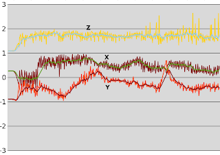
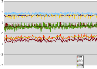
  The altitude was manely unaffected by bank.  X & Y were pretty bad.  There is an oscillation from the rotation.  If 1 frame per rotation is counted instead of the 3 in which the blob is visible, the oscillation would go away, but fewer data points would be averaged.
  X & Y seemed roughly aligned with magnetic N.  Further alignment would require stabilizing the test attitude.
 

marcy2_49.jpg


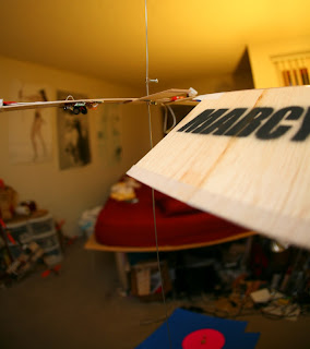
The mane event was devising every possible test for position sensing.  Position sensing from a rotating camera & all the trigonometry required was too crazy to believe it would work.  There were a lot of electronic dongles hanging in mid air.  Crashing would get expensive.

When Marcy 2 was originally conceived, there was full confidence that everything currently on the air frame was physically enough to do the job.  Confidence wanes when it's built up & sitting on the test stand.

The leading technique was the old ceiling hung wire, but it didn't constrain bank angle.  As expected, the bank angle drastically impaired position sensing.  When level, the azimuth correlation & blob detection seemed to work.

There were a lot of obvious glitches which the deglitching couldn't handle.  The camera detected noise as the target when pointing away from the target.

Thus, the error prone test of a minimum blob size was required.  Manely, the largest blob in the last revolution was taken.  Then, all blobs below half its size were excluded.  A blob greater than 1/2 the maximum could sneak in when the camera was pointed away, for which deglitching would be required.  A real paranoid filter could take only the largest blob from the last revolution.

She already has trouble differentiating from the Heroine Clock.  This is the reality of machine vision.

marcy2_50.jpg

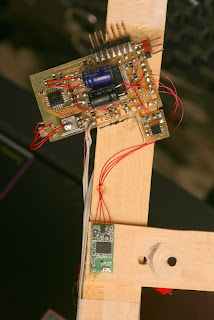
The quest for a more robust electronics arrangement continues.  The mane board can be repaired, but the wifi card has a $5 tag & works better near the axis of rotation.

Fly & crash she did.
vision18.jpg
 Revealing no useful position information during the flight.  The takeoff attitude hold was so accurate, it kept the target halfway off the screen during the complete flight. All the energy getting the camera to view the axis of rotation didn't get enough of it in view to give a target.
  The attitude hold stays active until the takeoff altitude is reached, just like ground based vision.  Only then does it switch to position hold.  It's probably acceptable if the takeoff altitude is low.
The current blob won't do.
vision19.jpg

vision000100.jpg

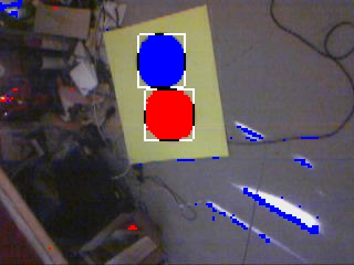
Then there were 2 markers.  Sunlight caused some blue in the chromatic aberration. 

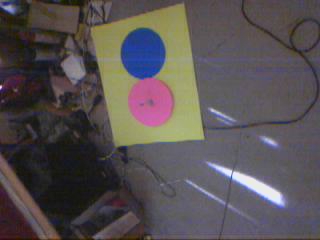
Having 2 markers creates a lot of possibilities.  The overlap of the 2 markers can be used to throw out false blobs, but also eliminates some real blobs.  The distance between the 2 markers & size of the 2nd marker can give a better distance measurement, but the distance is affected by rolling shutter.  The blue marker can be visible sooner in the takeoff.


You can see how more targets could be added & detected based on proximity.  Then, the position could be even more refined.

Of course, blue immediately showed the same horror glitches it did before.  Light blue might work better, but it's not mass produced.  Maybe if all blobs were thrown out that weren't a red & blue next to each other.

That was disappointing, but there's hope some simple shape detection is possible or some redundant marker can work in the 1st moments of takeoff.  Such a diabolically complicated system like that brings to mind the idea of detecting position from a partially obscured blob.

The radius & center can be derived from the dimensions of the rectangle.  But that also depends on rolling shutter.

A 2nd pink circle would be hard to separate from the 1st.  Enough testing could define a minimum distance to resolve the 2.  Then they could be mounted on a blue background, guaranteed to not generate a false positive.  How would it know where the maximum distance between the 2 blobs ended & ambient noise began?

It could measure the size of the small blob & compare it to the distance from the big blob. 

vision20.jpg

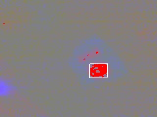
The small blob isn't big enough to get any size & if only the small blob is visible, it'll trigger a false positive.  The scanline compression takes away a lot of photons.  Some rough, procedural shape detection may be the only way.


vision21.jpg


A line was also worthless.   At flight speed, it takes a lot of photons to trigger the mask.

vision22.jpg


Blob matching based on overlapping boundary boxes of the red & blue got rid of some pretty significant blue noise.  Boundary boxes aren't as robust as scanning every red pixel for a neighboring blue, but faster.

vision24.jpg


The final attempt in this red/blue combination was scanning every red blob pixel for adjacent blue pixels & taking the largest blue blob.  This was bulletproof at separating the red/blue marker from the noise.

It was a leap in intelligence, actually detecting details in a noisy image from a spinning camera, with complicated rules for switching to the blue blob when the red blob was obscured & throwing out all red blobs without an adjacent blue blob, except during takeoff. 

vision25.png


Surprisingly, the blue & red blobs seemed to give very consistent results, right down to Y offset between blobs.


In the worst case, 1 original plan if the camera couldn't look straight down was to have the red off center for all position sensing & the blue for the takeoff leveling with a new requirement to not hover directly over the red.

vision26.jpg


Another test flight & another crash as the denoising algorithm throws out good data.  If the aircraft rises too fast & the blobs get small too fast, they get thrown out for being too small.

There were only 20 good frames it could have used during the takeoff, if it worked.   


Anyways, started thinking more about tethered power.  The 10 minute flight time & cost of crashing batteries over the years is such a turnoff, it makes you think surely the infinite flight time of a tethered system can outweigh the drawbacks.

It's been sold before as a finished product, with limited results.  Maybe it was sold to the wrong customers.  Someone interested in a flying camera for photographing on a closed set would be better off with a tethered system.  Hobbyists are manely interested in hovering a camera in a stationary location.

The mane limitation of all FPV videos is they have a very limited horizontal range, beyond which they always have to turn around.  It's hardly enough justification for batteries.

The ideal tethering system has an insulated wire for V+ & uninsulated wire for ground.  The wires are as thin as possible.  The voltage on the ground is much higher than the motor voltage, to compensate for resistance.  The motors are wound for very high voltage & low current.

The monocopters can't be tethered.

Read more…

Aircraft Design for Fail

1879556705_a5c17a7118_o.jpg

Modern fault-tolerance design for aircraft does little to help when big parts start falling off. This study proposes a design approach / philosophy for keeping things aloft during broader system failure.

From PsysOrg: /
"For example, the group studied the plane’s operation during a maneuver called the “Dutch roll,” in which the plane rocks from side to side, its wingtips rolling in a figure-eight motion. The potentially dangerous motion is much more pronounced when a plane’s rudder is faulty, or one of its engines isn’t responding. Using their design approach, the group found that in such partially failed conditions, if the plane’s tail was larger, it could damp the motion, and steady the aircraft.

Of course, a plane’s shape can’t morph in midflight to accommodate an engine sputter or a rudder malfunction. To arrive at a plane’s final shape — a geometry that can withstand potential failures — de Weck and his researchers weighed the likelihood of each partial failure, using that data to inform their decisions on how to change the plane’s shape in a way that would address the likeliest failures.

De Weck says that while the group’s focus on failure represents a completely new approach to design, there is also a psychological element with which engineers may have to grapple.“Many engineers are perfectionists, so deliberately designing something that’s not going to be fully functional is hard,” de Weck says. “But we’re showing that by acknowledging imperfection, you can actually make the system better.”

Read more…

IMG_2721.JPG

Story
I was wondering about PPM decoder for a while. I liked to have receiver on edge of the wing, but routing of all servo cables there is nonsense.  My idea to build one came from accident when I damaged my one of APM1’s main MCU  I2C pins. I replaced it with new one and then I get idea to reuse damaged MCU for PPM decoder (I2c wont be needed) They are not cheap (ATMEGA2560 are 18$ in mouser) and it's a pity to throw it away. I realized that APM uses sum PPM signal and can drive 8 servos by hardware timers and has libraries for it so software can’t be too hard. I fired up Eagle and started to draw....

Hardware design
I peeked in schematic of APM1 and duplicated servo and PPM pinout. Basically, you can use APM1 without oilpan to do the same! Then I realized it would be a good idea to do galvanic isolation of receiver to suppress any interference coming through the wires. This is really simple, just isolated 1W DC/DC 5V/5V converter to power receiver side and ADUM1301 isolator IC. Simple optocoupler would do the job well, but I was too lazy as ADUM’s are really simple to work with. It is quick and dirty design at all, board is autorouted with some hand corrections. Parts are chosen to be obtainable in local store here in Czech.

Prototype
I soldered all stuff on board, powered it up and arduino bootloader was not answering :) Long story short, failed crystal. With new one, everything goes well. I still haven't ADUM1301 IC, so there is a piece of wire instead. But receiver has its own power via DC/DC.

Software
This was easies part. I just compiled \ArduPlane-2.32\libraries\APM_RC\examples\APM1_radio\APM1_radio.pde it was all I needed to do! This example is doing exactly what I needed. Decode PPM signal and send it to servos. Well I commented out serial debug messages and added blinking of LED.

Real life tests
I was really brave (or stupid) to put this to my greatest, most expensive and most labour intensive plane ever, UltraMaxiSwift (will show it in another blog post) and even together with my own OpenLRS clone. Everything is working well, it has about one hour in the air.

Future development
When I fix my APM completely, it will replace this decoder. Maybe I will use it in other plane.
But one thing worth to be experimented. If I add second PPM receiver, Decoder can do a sort of diversity. It would choose valid PPM signal from second receiver if first goes to failsafe or vanishes completely.
Is ATMEGA2560 (or 1280) able to decode second PPM stream? I offer piece of hardware to someone who will write software for it :)

Pros and Cons
+ Place receiver freely in airframe
+ Galvanic isolation to help avoid interference
+ Possibility to alter RC signal (mixer, complex failsafe...)

-When this thing fails your plane is doomed
-Not need when APM onboard as it has PPM input
-ATMEGA2560 (or 1280) is expensive overkill for such simple task

Conclusion
If you like this, send my board design to your favourite fab house and DIY. Probably not needed by most of you. I wanted to thank all APM community for such great project.


IMG_2724.JPG3689462411?profile=originalrcisol.zip

Read more…
Moderator

3689462216?profile=original

Our friends at MaxBotix have updated their offering of ultrasound sonar sensors by adding the new High Resolution LV line. The defining characteristic of this new line of sonars is the 1mm resolution. Yes. 1mm. Well, more correctly, "the HRLV-MaxSonar-EZ Sensors offer calibrated 1 mm accuracy of 0.1% at 1 meter," so at greater distances, the ranging might be off by a millimeter or more. Up to 5 millimeters at 5 meters, if the accuracy were linear. I can live with that. *grin*


The new sensors offer a similar near end range, a minimum of 30cm, and the data sheet describes a 5 meter maximum range. This is slightly shorter than the 6.4 meter maximum range of the LV line or the 7-10 meter range of the XL, but my thinking is beyond 15 feet off the deck, you might not notice if your multicopter switches to using the barometer for alt_hold. Like the other product lines, the specifics of range are most likely subject to the beam pattern. As with the LV line, it is available in a variety of beam patterns off the shelf, and they offer custom solutions for customers who require it. 


This new sensor line offers the same interface as existing sonar products, including analog, serial/TTL, and pulse width, comes in the same form-factor we to which are accustom, but the manufacturer provides details on additional distinguishing characteristics of this new line over the LV line, including:


  • Higher resolution output
  • Automatic calibration of, noise, humidity, and voltage for consistent, long term, operation.
  • Automatical compensate for speed of sound changes due to the effects temperature changes
  • Advanced firmware to handle a variety of noise sources
  • Simultaneous multiple sensor operation
  • Noise filtering is even better than previous MaxSonar products
  • Automatic target size compensation

With this level of resolution, I expect there are new technical challenges related to air temperature changes in near-real time, and this suspicion is somewhat supported by two features of this sensor. First, there is it's onboard support for compensation of "self heating" through an onboard temperature sensor. Second, there is support for an external temperature sensor, also available from MaxBotix, which when combined with the onboard temperature sensor, can eliminate a potential "drift of ... up to 3%."

The product page also reports that the HRLV are designed to support simultaneous sensor operation, but it is not clear from the initial information if this is handled through time triggered operation, as with the other sonar lines, or if this sensor discriminates between its pulse and those of other nearby sonar units in some new fashion.

Here are the beam patterns available off the shelf. 

3689462302?profile=original

There are a range of other features worth discussing, but let me not distract you from the important questions. Or rather, the important question. With this type of high resolution, I would expect this sonar to come at matching high price. Like the LV and XL lines, different sensors are priced differently, but t The lineup is advertised at MSRP $28.95 - $34.95 for a single sensor, with volume discounts available.

I should mention right now that I have no ties to MaxBotix, except as a fellow customer. I don't get any discounts by bringing this news to you, and at these prices, I don't really need any (but I'd gladly go in on volume purchases if anyone wants to organize some, hint-hint 3DR team.) I was notified by email about the new line in a product announcement email. And that is important to this audience because it also informed me of another useful bit of information. These sonars are begin offered at a 25% discount until 7/15/2012 if you use the discount code en4v en4V [the code is case sensitive.]

A quote included with the product announcement (not attributed):

“1-mm resolution is so stable, that when measuring typical objects at a distance of one meter, the readings do not change by more than 1-mm.”

See the linked data sheet or the product Web page for more information.


Read more…
3D Robotics

DIY Drones at 26,000 members!

3689462330?profile=original

As is customary and traditional, we celebrate every new 1,000 members here and share the traffic stats. This time it's 26,000!

There were 1.3 million page views this month. As usual, it took us four weeks to get this latest 1,000 members--we're averaging about one new member every 43 minutes.

Thanks as always to all the community members who make this growth possible, and especially the moderators who approve membership applications and blog posts and otherwise answer questions and keep things ticking here. We've got about 50 moderators now, but if anyone would like to join this group, please PM me. If you've been here for a while and have been participating, you'll fit in great.

Read more…

Hunter%20Vtail.JPG

The Hunter-Vtail 500mm frame, available from QcRc.ca, is constructed in black G10 and uses aluminum standoffs. It uses an unusual arrangement of motors, with which "the yaw autority is not only managed by the torque of the motors, back motor are producing a vector of thrust that push the tail of the copter one side or another, so it move really fast. Another great thing is, the center frame go way in the front allowing you to place a camera to fly FPV or film a HD image ( such Gopro camera ) that will not see propeller !" [sic]


It should be noted that the vendor recommends the use of the Rushduino Flight Control board, and this frame and configuration has not been tested with APM yet.

Selling at $95 Canadian, maybe some members would consider buying some of these for a developer or two who might consider spending some time working out APM support for this frame? Any volunteers for either role (donating frames, coding/testing APM support?)


Read more…

An APM2 for the South Carolina Arducopter

3689462234?profile=original

On second thought, maybe ordering the APM2 assembled would have been a good idea.

Nah, why let someone else have all the fun? The board is wonderfully small and has convinced me that SMD components require learning new tricks if I plan to roll my own in the future. Over 35 years of through-hole work only qualifies me to solder in the header pins.. barely. You see a very vintage grounded Ungar iron and the ESD packing on my bench acting as my base ground ("Where's my anti-static mat?")

 I could not locate an order of assembly for the 'kit' version of the on-board GPS (the APM1 has one) so...

Here is what I did:

  • Drop the single pins into the main board first (short pins through the mainboard)
  • Then use the GPS module to hold them somewhat down and in place (plastic 'block' between main and GPS).
  • Solder the pins on the bare (back) side of the mainboard first.
  • Then solder the 4 pins in the purple section of the GPS board from the top. These are the Vcc and Gnd connections to the GPS module. I left the two pins at the GPS 'chip' end unsoldered. They look that way in the 3DR pictures.

The GPS header connector was not marked with Vcc or Gnd. This implies the power and return (earth, ground) are delivered through the single pins. If I missed the markings, at least the board is mechanically intact if/when an uncontrolled impact should occur. Besides, the pictures of the pre-assembled APM2 seem to show those pins soldered from the top.

Why did I go with the kit? I wanted the 90 degree connectors for the inputs/outputs rather then the stock units. I think cable management will be neater this way. When I get APM2 in the Quad stack up, this will be confirmed or recanted.

My plan is to do bench testing of the APM2, Mission Planner, etc before even thinking about trying to get off the ground.

Last week I purchased a Hitec X1 AC Plus Multicharger and an Eflite 3S 3200mAh LiPo from my local hobby shop (previously mentioned in the first blog post). More to do is matching up connectors from the battery to the PBD on the quad. Also to make up are the stack up plates for the APM2 and RC Rcv section. Writing the Gcode for these can be time consuming but it will allow me to create spares if they are broken while learning to fly. I think I will buy interconnect cables from 3DR. We've got to keep folks employed afterall.

Read more…
Moderator

Specter 360 CS UAV gimbal system

Hi All

I am glad to tell you that we have started with first air test of our small gimbal. This is under 600g, affordable, 2 axis control and stabilization system with 10x zoom great quality camera.

After analyzing global gimbal market we have decided to make a step forward and do a low cost, high-tech, reliable gimbal system all of us could use.

If this hits a good response we will put the system in production at the end of the summer.

We still have a lot of work to do. Stabilization is still not dead locked, integration with ardupilot, testing of different mechanical components, optical tests, endurance tests....

here is the link  https://www.youtube.com/watch?v=uX-ZIX6Ot8I

Read more…
Developer

John Deere's TANGO E5 autonomous lawnmower

johndeeree5.png


It's like a Roomba with blades?

Pah! 


I just fly my quad upside down over the lawn and get the same result!

Autonomous? Well.. kinda: "This space has to be defined by a user/specialist dealer installed boundary wire that helps to keep the mower from heading across the road and visiting your neighbor’s petunia bed."


http://www.gizmag.com/john-deere-tango-e5-robot-lawnmower/22940/


Read more…
3D Robotics

3689461991?profile=original

Drivers in Washington DC freaked out by sight of an X-47b being towed on a flatbed truck; think it's a UFO. Washington Post story here, including the amusing Twitter response I quoted in the headline, which came once citizens were informed that it was just a military drone. 

Read more…
3D Robotics

3689462173?profile=original

IEEE Spectrum writes:

In October of 2009, we wrote about the very first version of EPFL's AirBurr micro air vehicle, called HoverMouse. It was an innovative design: a roll cage protected the MAV's engine and flight surfaces, enabling it to crash into walls and floors without damage and then take off again, provided it had enough room to get airborne. Seven iterations later, the AirBurr V8 Samurai includes an active self-righting mechanism that allows it to crash and take off again even in rugged and cluttered environments.

AirBurr's latest trick involves first crashing into something and falling to the ground, which I imagine was a pretty easy thing to get it to do. Second, the MAV rolls over onto its side thanks to a clever arrangement of carbon fiber caging plus a carefully designed center of gravity. Third, AirBurr activates an "Active Recovery System" consisting of carbon fiber legs that deploy out from the body, pushing the body of the MAV into a vertical position from which it can lift off straight up. Watch:

Read the whole IEEE Spectrum piece for lots of pictures of previous versions and background on the research.

Read more…

3689462092?profile=original

Hi DIYDrones community! Amazing work you guys are doing!!


We're a group of researchers from Goldsmiths University London, supporting migrants rights organizations in Europe and North Africa to document and bring accountability for the death of migrants at the EU's maritime borders.

We're setting up a platform - watchthemed.crowdmap.com - using all kinds of technology to try and document and map violations in the Mediterranean. We're doing this in collaboration with Boats4People, an important international campaign that will take place this summer between Italy and Tunisia, coalescing around a solidarity boat that will travel between the two shores. http://www.boats4people.org

We thought of trying out drones to monitor the med, fly banners, launching them from from the coast or the solidarity boat. But for our project this summer - 1-20 July - it will be too tight for us to experiment with this technology on our own...

We just wondered if someone in your community might be based in Italy or Tunisia and just might want to experiment in support of our project...

For more info and contacts please view the document attached.

Thanks for your attention on short notice, if not for this time, we'll surely be in touch in the future!

Best, Charles

FO_B4P_08.06.2012_short.pdf

Read more…

Custom made UAV Airframe

Hello all,

3689462126?profile=original

We're releasing a brand new UAV airframe featuring super light weight glass fibre laminate construction with carbon fibre and kevlar reinforcement in critical stuctural area. All removable 3 piece wing, tail booms, v-tail and 2 large hatches allowing excellent access to fuselage internal area. All wing and tail surfaces are hollow composite mouding which you may install extra hardware in the central wing section.

The airframe comes with carbon fibre main landing gear and machined aluminium steerable front wheel assembly. All nuts, bolts and nut plates are mil-spec.

This airframe is made to endure the daily usage and handling using lesson learned from hundreds of hours operating other UAVs in theaters. You may choose to buy an empty airframe or with any of the optional items listed below

Alternatively you can also request a full carbon version which will be even lighter but be aware if use 2.4ghz RC gear in a full carbon airframe may not yeild happy ending!


Specifications:


Wingspan: 2500mm / 98"

Length: 1767mm / 69.5"

Gross weight: 11kg max

Control: Ailerons, Flaps, Ruddervators, Throttle, Steering

Recommended engines: 26cc to 50cc 2stroke or 4 stroke gasoline or equivalent eletric motor

Options:

- All control linkages and mil-spec wiring harness setup and installed

- High power Hitec servos or UAV grade servos

- Installation of engine of your choice with all fuel tanks and fuel system installed and tested

- Onboard electrical generator - please specify how may watts you want and voltage 12V or 24V typical

- Integration of autopilot - we use CloudCap Tech, UAV Navigation or Micropilot

- Navigation and Strobe lights (aviation grade)

- Transponder

- Fuel injected 2 stroke or 4 stroke engine

- Balistic recovery parachute

We're in Melbourne, Australia and we'll have our website up shortly with other products. Feel free to contact me at this time for pricings and options.

Ryan

Read more…

Hello

wr703n.jpg?width=750

I found that lot of people discovered this new feature of the wr703n flashed under openwrt : It is able to stream an USB webcam (soon a Gopro using an easycap) and also to make a bridge between a serial interface (USB according to CDC driver or 3.3V TTL).

see : http://www.diydrones.com/profiles/blogs/hacking-a-rc-helicopter-for-wifi-router-control

Here is the tutorial (3 parts + 1 part unbricking ;) ) on Openpilot Forum : http://forums.openpilot.org/blog/52-fertitos-blog/

So I started a TUTORIAL to help those that would like to add this feature on theyre drone and start developping new sensors :

I'ld like to work on a laser line avoidance system using the webcam :

scan.JPG

If you have question... ;)

Read more…