All Posts (11086)

Sort by

Post 2. MAAXX-Europe. The Groundhog Hardware

3689711612?profile=original

The Groundhog was at least twice as big and probably three time as heavy as many other competitors.  Why?  Because it is built for endurance (flight time 35mins+) and also because it's what I have as my development platform.  It normally flies outdoors of course...

Ah, so that means no gps and flying less than 30cm from the ground also rules out an optical flow camera (they can't focus that close).  So how to control this thing?

The answer (as you will see) is using the GUIDED_NOGPS mode now available in Arducopter, but I suspect, little used.  This is because almost the only control available is to set the pose (pitch, roll, yaw) using quaternions.  Not velocity, not even altitude.  It's going to be a little like controlling a 3Kg ball bearing sat on top of a football.  Fun.  But we are getting ahead of ourselves.  Back to hardware...

Specs:

  • Mass - 3.0 Kg
  • Diameter - 0.98 m (with guards and reduced props to fit competition regs).
  • Airframe - HobbyKing Tarot 680 Pro
  • Motors - Multistar Elite 3508-268KV High Voltage Endurance
  • Props - 10 x 4.5 plastic (normally runs 12 x 5 carbon fibre)
  • ESC - Afro HV 20A MultiRotor ESC High Voltage 3~8s
  • Batteries - 2 x Multistar High Capacity 4S 8000mAh Multi-Rotor Lipo Pack (in series)
  • Flight Controller - Pixhawk running ArduCopter v3.4
  • Companion computer - Raspberry Pi 3
  • Camera - PiCam 2 with 9g servo gimbal for roll and pitch.
  • Receiver - FrSky 8BR
  • Ancilliary power - 2 x Turnigy HV SBEC 5A Switch Regulator (8-42V input)
  • Maxbotix sonar (I2C)
  • Sparkfun VL6180 TOF Range Finder (I2C)
  • Prop guards and superstructure - 3d printed and 4mm pultruded carbon fibre tubing.

Airframe

The hexacopter Tarot 680 Pro is my general purpose airframe for just about everything.  Here the props are turned downward facing to get them closer to the ground to increase ground effect.  Smaller 10 inch props were fitted to bring the overall size down to less that 1m, as required by the competition.  This meant the motors were running faster than usual, reducing efficiency.  Hey ho.

Power Train

The two 4s batteries are configured to run in series, so 8s is provided to the high efficiency motors which are designed for endurance.  The power module for the Pixhawk was taken from just one battery - making sure that they had a common earth!

Power for the RPi and servo gimbal is provided by 2 x SBECs, taking power from across both batteries.  The feed for the SBECs is taken from across the supply of one of the speed controllers.

Key lessons:

  • Don't involve the Pixhawk power rail in any way to power the RPi or servos.  It may brown out.
  • Use one SBEC for the servos.
  • Use a separate SBEC for the RPi.

Pixhawk

Flight control is provided by the Hobbyking version of a standard Pixhawk.  It is attached upside-down to the underside of the top plate (underneath the RPi).  Don't forget to reconfigure Arducopter in Mission Planner to tell it the Pixhawk is upside-down (mode 12).

Raspberry Pi 3

In earlier blogs I had overclocked the RPi 2 to beef up performance.  This is not required for the RPi 3, which is a big improvement and is used out of the box with the Pixel operating system.  However, configuring the serial port (for connection to the Pixhawk) correctly took ages, as it is also used by the Bluetooth interface.  Pay close attention in the forthcoming post to the change in the config file required and then the correct syntax to open the serial port and it will be easy.  I'll put this in the post on Control, but it took weeks and weeks to eventually sort out!

The RPi is connected to the Pixhawk using the serial cable in precisely the same way as detailed in one of my previous posts here.

Sensors

Vision

A standard PiCam 2 is controlled for pitch and roll using a gimbal controlled from the Pixhawk.  This gives a steady and level view of the track to reduce the image processing burden.  It worked beautifully, and incidentally is exactly the same strategy also used by the 2nd place team (so I know it's a good idea!).  Also, we want a forward looking camera so we can see further and go faster - not just looking down.

3689711559?profile=original

Altitude

For low level flight, a VL6180 time of flight range finder sensor more usually used for gesture recognition is deployed and strapped to one of the front arms.  This can give altitude to mm resolution between 10 and 20 cms.  This is connected to the I2C interface on the RPi as there is no provision for this in ArduCopter for the Pixhawk.

3689711549?profile=original

That's it for now(I'll discuss the Maxbotix later).

Coming next: Image recognition using Python and OpenCV.

Read more…

Eli Drone Nest

Our Drone nest is the newest project what have we worked past year.
We have come a long way with our small crew.

3689712242?profile=original

Eli Drone Nest can hold up to 5 Batteries, what will charge and what will be in storage is going to be the software decide.
We also have heater element inside the batteries to be constantly 20C-30C to get the maximum out.

3689712373?profile=original

Elix-XL Drone.

http://www.uav.ee/

Here is a short video about the landing and Battery changer !!

https://www.youtube.com/watch?v=k88oFmXDu2c

Read more…

In the last two months I was exploring an idea of using a haptic device to control a multirotor. Here is the video I made showing the system working in simulation:

The setup

For the simulation I used Px4 SITL running with jMAVSim. For interfacing with Px4 I'm using mavos + two custom ROS nodes. If you are interested in trying it yourself then you can find all source code in the following repo: https://github.com/msadowski/px4_falcon .

The diagram below roughly shows the architecture of my system:

3689712027?profile=original

Results

In short: I wouldn't use Novint Falcon as casual 'controller' for UAV. I found the device to be slightly unreliable (sometimes motors stop for about 1 second). Nevertheless I still consider this concept to be quite interesting. Obviously it can only work in stabilized modes where you control groundspeed. One personal advantage I have from this project is that I probably could use whatever device that produces sensible output to control a Px4 based system.

Unfortunately at this time I cannot test the system with a real drone. As soon as I get hands on Pixhawk I will try to set it up and post an update.

Future work

I'm not planning to put too much more effort into this project as there are many more things to explore. I'm happy however to accept pull requests on improvements and fix any potential bugs.

Some remaining work:

  • Implement yaw rotation using digital buttons (lame, I know)
  • Implement homing mode on starting program (for offsetting Novint Falcon encoders)
  • Programatically establish minimum and maximum values for positions received from Falcon for each axis
  • Clean up the code
  • Review offb_node.cpp timings (especially refresh rates)

More info

If you would like to know more about the project then here are some links:

  1. Github repository with the project: https://github.com/msadowski/px4_falcon
  2. 1st blog post: https://msadowski.github.io/1ppm/uav-haptic-control-pt1/
  3. 2nd blog post: https://msadowski.github.io/1ppm/uav-haptic-control-pt2/
Read more…

3689711931?profile=original

Great news for the open source  community and the greater world of autopilots: On February 27th Ardupilot.org was selected as a participating 2017 Google Summer of Code organization.

Sponsored by Google, GSOC is a unique program matching open source organizations and students interested in participating in open source development.

Students: Spend your summer break writing code and learning about open source development while earning money! Those accepted  in the program will work with a mentor,  working directly with world class programmers. Many past GSOC students also became lifetime open source developers!

Google Summer of Code is open to post-secondary students, age 18 and older in most countries.

Those interested can find out  more information about this unique opportunity here.

Read more…

3689711700?profile=original
UgCS has been developed for more than 4 years and it is used in 159 countries - a fact that motivates us to continue improvement of UgCS. Although our Customer team would be glad to travel to 159 countries, but understanding, that we can’t meet all UgCS users in person - we send sincere greetings from Latvia! :)

List of most UgCS users by country is quite ordinary, in the TOP 10 listing biggest countries of the world. There are also some surprising countries in this list like Vatican, arising the question, is it possible to fly a drone over Vatican, really? Greetings also to UgCS bravest drone pilot! :)

Chart: TOP 10 countries with most downloaded UgCS Licences


3689711704?profile=original

China seems as our epic fail. With more than 1 billion people population there should be more drone pilots among UgCS users.


Paid to free licence ratio

Country

Paid / free licence ratio

Spain

20,49%

Canada

20,40%

Australia

17,01%

United States

14,23%

Other countries

13,04%

Germany

11,99%

Brazil

11,70%

France

11,50%

Italy

10,46%

United Kingdom

9,19%

China

7,34%

We are grateful to DIY DRONES community for feedback and support. The ratio between paid and free licences of UgCS in TOP 10 countries shows, that UgCS OPEN is widely used by hobbyist and semi-professional drone pilots:

These numbers convince us to continue offering the free licence UgCS OPEN as a full-fledged ground station software.

Get UgCS here: https://www.ugcs.com

Safe flights,

UgCS Team

Read more…

Hello friends!

We are introducing the new Professional Protogrammetry Quadcopter Harfang RTK. This is a Ready to Fly Drone, aimed to Professional users with a Low Price point and High End features. Flies 30+ minutes and complies with "light weight" standards! 

3689711966?profile=originalBased on the familiar Pixhawk Autopilot, a mainframe made by France's Lab4Drone and broadly used Spain's North RTKite GNSS RTK receiver, the Harfang RTK is fully made in Europe and supplied worldwide.

The RTKite GNSS Receivers allows to eliminate or minimize the GCP on the field while incredibly stabilizing the navigation with its millimetric real time accuracy. It can connect directly to the available NTRIP CORS stations with its onboard mobile cellular modem, Receive corrections from an RTK Ground base by GPRS through the exclusive AutoCaster system or use the Pixhawk RF from the ground control to receive the RTK corrections from an SmaRTK Base receiver.

3689711986?profile=original

This carefully crafted collaboration between a high-end drone producer and a professional RTK supplier, makes sure that the integration is seamless and the most easy to use out of the box.

3689711911?profile=original

The exclusive Patented drone mainframe is designed from high-quality carbon fiber rods and a simplistic Snap-On design where the spare parts can be produced in house by the end user by simple rod cutting and 3D-Printing if needed, greatly reducing the repairment costs on site.

3689711800?profile=original

The Harfang RTK Drone with North RTKite GNSS RTK Receiver, comes with a selection of entry-level Sony Camera, Professional Sigma camera or Multi-Spectral Parrot Sequoya camera, to fit most purposes.

3689711920?profile=original

Regarding the GNSS it can operate on either Single, RTK (Real Time Kinematic) millimetric, PPK (Post Processed Kinematic) millimetric and a vast array of data logs and formats including all the NMEA standards, Novatel's Raw and Bestpos, RTCM, Trimble's CRM, RINEX and many more.

The Harfang RTK drone, as well as the RTKite receiver and the ground SmaRTK Base receivers can be easily ordered online and you can contact us at North Group for any special set configuration not available as ready-made sets.

Just drop us a message!

Read more…

Circuit Board for DIY Arduino Micro-quadcopter

3689711775?profile=original

In this project, I will go through the process of designing and making a flight controller board from scratch for a micro-quadcopter. This board will be based on the ATMega328 microcontroller and will be used to control four coreless DC motors. The whole PCB making process from designing of the schematic to gerber viewing is done using EasyEDA. The main idea while designing the flight controller board was to keep it small, lightweight while still making it easy enough to solder at home. Therefore I chose to use as many SMD components as was feasible to solder. The ATMega328 chip and MOSFETs are the SMD components used on this board. Though in hindsight I have also used 1206 SMD resistors and capacitors as they are easy to solder even for hobbyists. 


1. Designing the schematic and PCB

If you are interested in the circuit project, you could access circuit and PCB project for the micro-quadcopter . The schematic designing process was very smooth and intuitive on the EasyEDA environment.  Anyone with previous experience in other circuit design tools would easily adapt to it. I found it much more preferable than dealing with messy etchant used for making home-brew PCBs. The circuit schematic is as image showed and could be edited Here: https://easyeda.com/editor#id=d26e0216b68649e0b102da0a51664bef

3689711856?profile=original

Using the Convert To PCB option the blank PCB and component footprints were generated. All the component footprints used were available in the EasyEDA Component Library. In case you cannot find the component, EasyEDA also has a handy custom component creating tool. The PCB outline, dimensions, hole dimensions, silk screen color can all be customized using the useful right-hand side menu on the screen. Screenshots of the PCB design screen below and can be edited Here: https://easyeda.com/editor#id=b6e2e30d14264213aea6a2ebbdde2108

3689711731?profile=original

screenshot-564-e1488252674427.png?w=640

2. Custom PCB and prepare compents for the Quadcopter

Once the PCB was designed and finalized, you can finalize the number of copper layers you need, the PCB thickness, copper weight, and even the PCB color from the checkout menu. There is also a handy option of downloading your Gerber File on the PCB order page and seeing the Photo View of your PCB (i.e. how it will turn out). And you also could custom circuit board with JLCPCB.

3689711873?profile=original

Then prepare main components used in this board are:

  • ATMega328 TQFP32 Package with 16MHz Crystal x 1
  • Si2302 MOSFETs x 4
  • 78L33 LDO Voltage Regulator x 1
  • NRF24L01 Transceiver Module x 1
  • MPU6050 Acc/Gyro Module x 1
  • Coreless Motors x 4

3689711742?profile=original

3. Soldering and Final Build

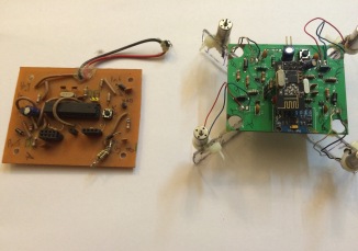
After all components on boards is soldered and the quadcopter is well built,  I can quickly go on to the coding and testing of the project. I have included some pictures of the final quadcopter build that I made using these boards. Also, I have included a picture comparing a home-made board to a professionally made PCB and you can see the improvement in quality. Hope you will enjoy this project. 

fullsizerender3.jpg?w=326&h=229&crop=13689711885?profile=original

Read more…

3689711640?profile=original

From Navio2 Project Shares:

This multi-rotor UAS will be used in search and rescue operations using object recognition to find a target and deliver a payload, e.g. to help an injured climber on traditionally inaccessible terrain needing to be dropped fluids, a torch, an insulating blanket and/or a flare to assist their survival and later rescue.

IMG_20170122_151419.jpg

A Mobius camera is connected to the Raspberry Pi with Navio2 attached, running an OpenCV application to detect objects. Their position in the frame is used to generate velocity data that is sent via DroneKit to ArduCopter, which then moves to center the drone above the object.

A full project description can be found at blog.mckeogh.tech23.

3689711595?profile=original

Read more…
3D Robotics

fathomnewFrom TechCrunch. It works on Raspberry Pi!

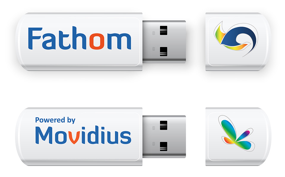
Following on the heels of their announcement a few weeks ago about their FLIR partnership, Movidius is making another pretty significant announcement regarding their Myriad 2 processor. They’ve incorporated it into a new USB device called the Fathom Neural Compute Stick.

You can plug the Fathom into any USB-capable device (computer, camera, GoPro, Raspberry Pi, Arduino, etc) and that device can become “smarter” in the sense that it can utilize the Myriad 2 processor inside of it to become an input for a neural network (I’ll come back to all this).

Essentially, it means a device with the Fathom plugged into it can react cognitively or intelligently, based on the things it sees with its camera (via computer vision) or data it processes from another source. A device using it can make its own decisions depending on its programming. The key point is it can do this all natively—right on the stick. No call to the cloud is necessary.

In addition to the stick, Movidius has also created a software system they are calling the Fathom Deep Learning Software Framework that lets you optimize and compile learning algorithms into a binary that will run on the Myriad 2 at extremely low power. In a computer vision scenario, Movidius claims it can process 16 images per second using a single watt of power at full-bore/peak performance. There are many other cognitive scenarios it can be used for though.

They have 1000 available for free to qualified customers, researchers and small companies that they’ll be making available in the coming weeks. A larger rollout is planned for Q4 that is targeting the sub $100 range for the device. So that’s the news.

The Complicated Part: What’s All This Business About Neural Networks And Algorithms?

Still, I wanted to understand how this device is used, in practical terms…to visualize where the Fathom and its software framework fit in with neural networks in an actual deployment. After struggling to grasp it for a bit (and after a few phone calls with Movidius) I finally came up with the following greatly simplified analogy.

Say you want to teach a computer system to recognize images or parts of images and react to them very quickly. For example, you want to program a drone camera to be able to recognize landing surfaces that are flat and solid versus those that are unstable.

To do this, you might build a computer system, with many, many GPUs and then use an open source software library like TensorFlow on that system to make the computer a learning system—an Artificial Neural Network. Once you have this system in place, you might begin feeding tens or even hundreds of thousands of images of acceptable landing surfaces into that learning system: flat surfaces, ship decks, driveways, mountaintops…anywhere a drone might need to land.

Over time, this large computer system begins learning and creating an algorithm to where it can begin to anticipate answers on it own, very quickly. But accessing this system from remote devices requires internet connectivity and there is some delay for a client/server transfer of information. In a situation like landing a drone, a couple of seconds could be critical.

Fathom

How the Fathom Neural Compute Stick figures into this is that the algorithmic computing power of the learning system can be optimized and output (using the Fathom software framework) into a binary that can run on the Fathom stick itself. In this way, any device that the Fathom is plugged into can have instant access to complete neural network because a version of that network is running locally on the Fathom and thus the device.

So in the previous drone example, instead of waiting for cloud calls to get landing site decisioning information, the drone could just make those decisions itself based on what it’s camera is seeing in real-time and with extremely low power consumption.

That’s sorta badass.

The Bigger Picture

If you stretch your mind a bit, you can begin to see other practical applications of miniature, low-power, cognitively capable hardware like this: intelligent flight, security cameras with situational awareness, smaller autonomous vehicles, new levels of speech recognition.

Those same size and power factors also make wearables and interactive eyewear excellent targets for use (albeit more likely in a directly integrated way rather than USB add-on). This is notable as Augmented and Mixed Reality capabilities continue to make headlines and get closer to the comfort zones of the general public.

And since Computer vision (CV) algorithms are one of the backbones that enable AR/MR to have practical uses, making CV function more powerfully and cognitively in a small footprint and at low power has possibly never been as important. I can see this kind of hardware fitting in to that possible future.

Strategically, this approach gives Movidius another way to reach customers. Obviously, they already have integrated hardware agreements with larger companies they are partnered with like Google and FLIR, but for smaller businesses that still may need onboard intelligence for their projects, releasing the Fathom as a modular, add-on opens a new market for small- or medium-sized businesses.

Read more…

3689711287?profile=original

The Challenge

I recently entered the first MAAXX-Europe competition to be held at the University of the West of England (UWE).  On the surface it's a simple challenge in which UAVs must follow an oval circuit of one red line, around 20m by 6m.  However, this proved to be anything but simple and with few rules about how many could be on the circuit at the same time...  you get the idea!

So before you read further, I didn't win (I came 4th of 6, which I am pleased with as a hobbyist up against university teams).  However, my hexacopter did complete a lap and I now know exactly what worked really well and what didn't!  And it's that knowledge I wish to share as part of the payback for all the open-source community help I have had in the last year.

So this might be of interest to you if you are interested in UAV image recognition, control systems and the systems integration of a companion computer (Raspberry Pi alongside a Pixhawk).

It's also a big thanks to Steve Wright of UWE and colleagues for laying on the event, which together with the UK UAV Challenge held annually at the UK Drone Show, promise to greatly accelerate our capabilities in this expanding market.

The Idea

To build an endurance UAV built for high efficiency, flying 20cm from the floor.  This would:

  • help win the endurance prize for the most completed laps.  Even going very slowly, a 30min+ flight time between battery changes would build up lots of laps.
  • Utilising ground effect would improve efficiency still further by 25%+.
  • Flying so low would avoid the carnage above given that several UAVs might be flying at once and avoid the need for collision avoidance strategies.

Because it was built to run at low altitude and is of fulsome size, when asked at the competition it was immediately named 'The Groundhog'.  Great concept, great potential - what could go wrong?

Blog Areas

What I'm covering:

  1. The hardware (airframe, avionics, etc.)
  2. Image recognition.
  3. Control.
  4. Lessons learned and what's next.

I'll deal with each area, post the code (warts and all) and evaluate the effectiveness of each.

3689711512?profile=original

The track and The Groundhog in action.  Line recognition was good - both accurate and reliable.  Except for the segmentation faults!

Read more…

This is the video our first flight of the Disco from Parrot using the Paparazzi UAV system. Most of the drivers where already available, except for the PWM output on Linux-based autopilot. Many thanks to the ArduPilot community and especially Andrew Tridgell for his help and tips to make this driver working for Paparazzi.

Original blog post: https://blog.paparazziuav.org/2017/02/24/flying-parrots-disco-aircraft-with-paparazzi/

Read more…

Maximized terrain awareness for drone pilots

This is my first post in a series called "FlightZoomer 3 Feature Previews".

One of the coolest features for the next release of my FlightZoomer apps is a terrain elevation map and a vertical situation display. The look&feel of these features strongly borrow from the VSD (vertical situation display) and the TERRAIN display of the real Boeing 787 (after which FlightZoomer is modelled). The ergonomics, that are developed for professional pilots should be good enough for drone pilots as well!

To see how the changing colors provide excellent situational awareness about the proximity to terrain while flying I strongly recommend to see the video above.

The following explanations provide some interesting background information about these features:


On this picture we see the VSD (Vertical Situation Display):

3689711273?profile=original

  1. There is a cut through the terrain along the current flight track (if there is forward speed) or heading (if there is no speed). If a flightplan is loaded the VSD shows a cut through the terrain along the planed route. All the waypoints are shown as well as the entire vertical flight profile of the planned route.
  2. On the left the white triangle is the airplane symbol at the current altitude
  3. The magenta line is the armed target altitude of the autopilot. It moves while adjusting the target altitude on the MCP which helps to set a safe target altitudes on the fly
  4. The white line shows the current flight path angle
  5. The terrain is shown in various colors
    1. Green are altitudes more than 50m below the aircraft altitude. Green terrain is considered as safe
    2. Yellow are altitudes less than 50m below the aircraft.
    3. Red are altitudes higher than the current aircraft altitude


On this picture we see the Navigation Display with the terrain layer switched on:

3689711410?profile=original

Again the colors have the same meaning as above.


How should yellow terrain be interpreted?

It is perfectly normal and acceptable (actually unavoidable), that the terrain will turn yellow on a final approach. On the other hand yellow terrain poses an increased risk of a CFIT because of obstacles or inaccuracies of the system.


Some more details about the implementation:

  • VSD and terrain map are updated with 1Hz
  • The elevation data of the terrain is downloaded from the internet on demand.
  • There is worldwide coverage at any required resolution (= zoom level).
  • There is a two stage caching of the elevation data in order to reduce internet bandwidth consumption and to achieve a high performance. 1st stage: persisting on the device, 2nd stage: in the heap for fastest possible access


And - for those who think "I have no idea what FlightZoomer is all about" - here are some high-level buzzwords about FlightZoomer:

FlightZoomer is distributed avionics suite on top of ArduPilot. It has a companion computer (a smartphone) that is connected via a cell-network-data-bus to a ground station that offers comprehensive instruments, a flight management system and an autopilot. These features allow basically to fly IFR.

Read more…

ArduSub + Ardupilot is Official!

3689711365?profile=original

From Rusty and Jacob of ArduSub:

Hello everyone, Rusty here at Blue Robotics. We're pleased to announce that the ArduSub project has merged with Ardupilot!This is a momentous occasion for the ArduSub project, with our two main developers, Jacob and Rusty, both becoming members of the ArduPilot development team. ArduSub is the first new vehicle type since the addition of ArduBoat in 2011, and is the first to take the ArduPilot project underwater! We've been looking forward to seeing this since the start of ArduSub!

Read more here ... 

Read more…

3689711311?profile=original

Event38 now offers Emlid Reach upgrade to its vast fleet of UAVs aimed on providing ready-to-go PPK mapping solution. Reach PPK enabled system is able to deliver centimeter-level accurate 3D models without use of ground control points.


Emlid and Event38 products are a natural fit as both offer professional performance at an affordable price. Emlid will provide Reach and Reach RS receivers, while Event38 will bring its leading expertise into upgrading the E384/6 aircrafts with PPK mapping bundles. Integration of the Reach system enables map collection at centimeter level precision. Check out the case study conducted by Event38 to learn more about the system’s real world accuracy tests.


Both E384 and E386 may be now upgraded with a mapping kit which includes Reach installation, precise timing integration and utility for post-processing and image tagging. Recently released Reach RS receiver is used as the PPK base station. Existing Event38 users can send their aircraft and camera for an upgrade, recalibration and test flight.


If you were thinking of starting drone mapping - it’s never been easier to get survey grade results so don’t miss the opportunity. PPK mapping bundles are now available on Event38 website with discounts.

Read more…

Tilt rotor/SLT hybrid

3689711257?profile=originalSeparate lift/thrust systems are growing fast in popularity, to the point that there are already a variety of commercially available systems.  They seem to be the future and continually get better.  Thanks to our developers, Ardupilot has some great features like holding position with forward thrust and is becoming very good at leveraging the benefits of an SLT system.  These systems have the potential to perform very well in windy conditions, since airplanes rely on wind to fly.  It is only a matter of time before the developers have it perfected.  The main argument against SLT systems, is the dead weight they carry around.  The large majority of propulsion weight, is dead weight 95% of the time.

This concept, the tilt rotor/SLT hybrid is an attempt to reduce this dead weight by using horizontal propulsion during both VTOL and cruise.  Compared to typical SLT systems, this would allow lift motor weight to be much lighter.  Unlike typical tilt rotors, nacelle propulsion could be highly optimized for forward flight while the usual structural requirements on the wing would be reduced with the wing being supported at multiple points along the span.

3689711225?profile=original

Nacelles could be controlled by differential thrust, containing an IMU and stabilized independently from the main body, eliminating the need for actuators or mechanics of any kind.  The nacelles would be able to tilt forward during VTOL to help with position holding as well as provide very powerful yaw control which is typically a problem for SLT systems.

Feel free to comment.  I would love to get some feedback, good or bad.

I have more info, images and videos about this concept here:

electronflight.com

Read more…

3689711187?profile=original

From Tridge at Ardupilot.org:

We just finished the ArduPilot Developer meetup in Canberra, Australia. Randy [Lead Arducopter developer] will be posting videos from the talks when he gets back to Japan, but meanwhile here is a nice video by Darrell Burkey of some of the activities over the weekend. ... Read more

Among other glimpses of goodness the video features the successful and  rather spectacular, IMO, example of  the Addiction X plane ( prior simulation work referred to here) hovering vertically on its  motor and  entirely controlled by  autopilot.  ( "Hands off" controller sticks, no pilot manual intervention). 

Read more…

3689710947?profile=original

Making a small, low cost laser scanner for sense-and-avoid applications has been a objective of mine for several years. What makes this project challenging is the cost and complexity associated with motors and their drivers to provide the motion, position encoders to provide accurate aiming information and slip rings to pass the signals through the moving parts.

In a typically anarchistic response to these limitations, we decided to throw out all of these parts and start again with a simple, low cost, digital servo bolted directly onto an LW20 LiDAR. I've used the DS-919MG servo from Corona for this example although most digital servos will work.

3689711118?profile=original

The servo doesn't go all the way around, so the field of view is limited. For a forward looking sensor this is a reasonable limitation, given that it is so inexpensive, small and the whole system only weighs 50g.

It is simple to connect up the LW20 to a servo because the hardware and software drivers are built in. There is one wire that connects to the PWM control line of the servo and we used a separate power supply for the servo because they tend to be noisy on the power rail.

3689711082?profile=original

Through the comms port (serial or I2C) of the LW20, the servo can be told to aim in any direction. There is also a command to switch on fully automatic scanning.

To make an energy efficient scanner it is nice to be able to scan in two directions (clockwise and anti-clockwise) in a continuously reciprocating movement. Unfortunately, low cost servos are notoriously tricky to use in this way because their internal control systems are designed to aim the servo in a static direction. If you try to change the aiming angle of a servo before the shaft stops moving then the shaft position always lags behind the requested aiming position.

For most applications, "servo lag" isn't a problem because the servo moves quite fast. However, the LW20 is updating 388 times a second and this is on the limit of how fast a conventional servo can accept changes in position. The result is that the position of the scanned image from a CW scan is slightly different from that of the ACW scan.

You can see the lag in the image below where the black line is the ACW data and the orange line is the CW data. The data points in this image have been thinned out to avoid clutter but the actual number of points in each scan is much higher.

3689711049?profile=original

Fortunately for us, the LW20 driver software includes compensation for the servo lag and with a few tries it can be eliminated almost entirely.

3689711101?profile=original

For the purists out there who want precise angular data, there is also a uni-directional scan available as an option in the software. This eliminates the lag problem altogether but the servo draws a lot more power when it is returning to the start position.

To help with setting up a servo driven LiDAR, our software genius, Rob, has provided a fully interactive GUI that lets you put in settings, add 2 dimensional alarm zones, eliminate fixed obstacles like landing legs and generally have a lot of fun. This GUI is part of the LightWare Terminal application that you can download for free.

3689711163?profile=original

A final word about the performance of this system. The LW20 is a very powerful LiDAR module so I had no problem getting good maps out well beyond 50m with some points reaching 100m. I was also able to use the first signal / last signal capability to capture both nearby obstacles and more remote surfaces at the same time while looking through trees and long grass at a shallow angle. In the image below, the blue data is first return and the orange data is last return.

3689711136?profile=original

For more information about the LW20 you can check out the LightWare website.

Read more…