
The key is a 2nd IMU for the yaw motor.

Basically, the roll & yaw motors trade places as IMU2 pitch goes from 0 to 90. The PID equations have a set of gains for the upright position & a set of gains for the swapped position. The PID equations for the motors are always solved for fully upright & fully swapped. The PID outputs are then blended based on the actual IMU2 state.
The gradient isn't linear. It's a sine wave. When IMU2 is pitched 20 deg over, it adds just 12% of the roll. When it's at 45 deg pitch, it adds 50% of the roll. When it's at 70 deg pitch, it adds 88% of the pitch.
The yaw motor output fades to 0 as IMU2 roll goes from 0 to 90. The world will undoubtedly move to a better algorithm involving a discrete cosine of some kind, but this solution seems to do the job, in the meantime.
The algorithm worked as described. The yaw motor could move anywhere without a loss of control, though this frame has very limited roll freedom. It was the 1st time the yaw coupling problem was solved outside China. At least for a short time, no-one else in America could do it. The mane problems are now a very wobbly frame, lots of cables binding, too much cogging in the DT700.
Both IMU's required heavy, shielded cable. There was once a page which said to only solder 1 end of a cable shield, to avoid ground loops. http://en.wikipedia.org/wiki/Shielded_cable
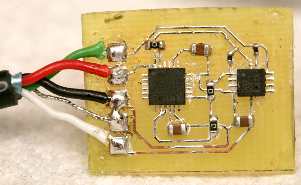
After fighting I2C glitches forever, remembering a Logitec webcam was connected to both ends of the shield, decided to solder both ends of the shield. That ended all the interference. So for an I2C device where the only return path is the signal cable, you need to ground both ends of the shield.
The forums & the experience of tuning the gimbal showed there is a limit to the amount of motion it can isolate. The amount of power, the speed of the feedback, the inertia in the camera, the amount of time spent perfecting PID gains, the speed of the MOSFETs, all conspire to limit its effectiveness. Brushless gimbals probably won't be stable enough for handheld astrophotography.
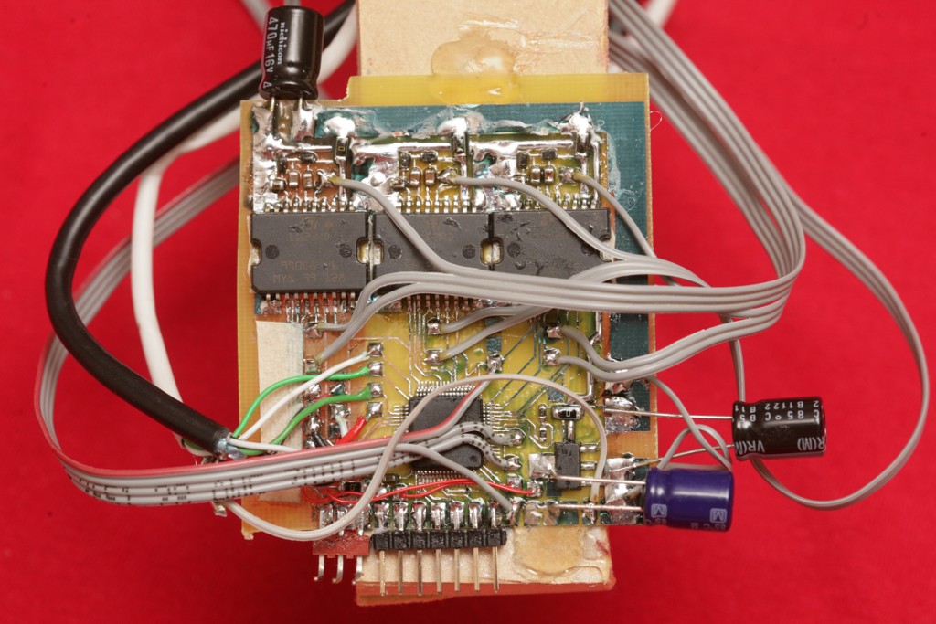
The gimbal has 1150hz feedback & a sin table with 1024 steps. The MPU9150 needed to be set to 2000 deg/sec to handle the oscillation of overdriven PID gains. The digital lowpass filter was disabled. Increasing sin table resolution had a noticeable impact on the motor smoothness.
The controller applies a constant current to the motor, regardless of the amount of motion. This should be the highest the power supply & motor can handle.


Unconventional trick to get by without a solder mask.


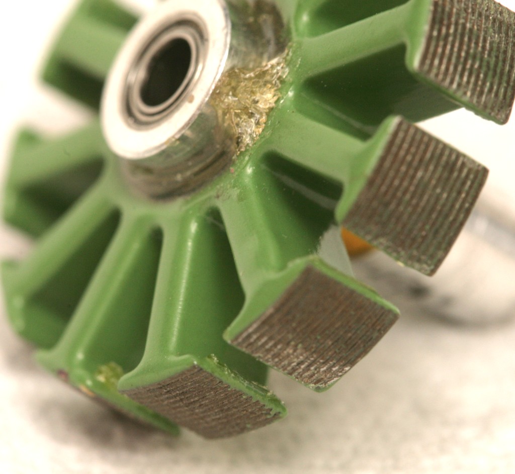


The yaw motor is 130 turns of 0.2mm on a DT700. It could handle 0.6A.


The pitch & roll motors were 50 turns of 0.2mm on a Turnigy 2205 1350kv. It could handle 0.3A. Ideally, it would be more turns of lower gauge wire. The forums recommend as many turns as possible.
Buying pre-wound motors is initially worth the extra money, but the selection is very limited. Once you've mastered winding, you're better off winding your own.
All these motors need to be heated to be unwound. Start the unwinding at the cable terminations, not by cutting into the windings. Make new windings with a narrow plastic tube. A long piece of wire insulation seemed to work best. The Turnigy 2205's were busters. They might be easier by grinding off as much of the enclosure as possible, without removing the screw holes.
There is a starting table of various motors:
https://docs.google.com/spreadsheet/...WWFl2Smc#gid=0
The problems with traditional 2 axis & 3 axis gimbals were documented. So basically, not knowing the orientation of the roll motor prevents any traditional gimbal from being an ideal isolator from all possible movements. The magnetic heading is probably not going to be available either, since it's influenced by the motors.
Yaw is coupled to roll/pitch when tilted outside a very narrow angle.
The 2 axis gimbal did a real lousy job stabilizing handheld footage. On an aircraft, a 2 axis gimbal is probably good enough. You can probably use the flight controller's IMU to aid the roll motor.
