Here is how I made a parallel battery adapter. Mostly because I didn't want to wait for an order from Hong Kong, but also because the commercially available parallel adapter uses #14 AWG wire, which is probably too small for my Hexacopter.
I tried to make one with wires, but I was never happy with my soldering.
I had the two male connectors on my bench when I realized that wires aren't needed:
I laid a piece of #12 solid wire across the three connectors as a bus, and soldered them together.
Then used a piece of heat-shrink that I had on hand to hide the burn marks from the soldering iron.
It definitely worked well. I got probably ten minutes out of today's combination of two cheap 2200's.
If you decide to make one yourself. I hesitate putting two high-power batteries in parallel without some kind of isolation.
Never store the batteries connected together. If one cell drops even a tenth of a volt, you have a dead short to the other battery. Use an inexpensive alarm on both batteries so that if either battery goes below 9V, an alarm starts beeping.
gh my phone.
All Posts (14049)
Sort by
While building and balancing my hexacopter (and rebuilding it after learning crashes) I frequently move the radios. Note the white tabs under the radios. These are 3M Command adhesive strips. By using these removable strips I can simply pull the tab to remove the strip and relocate the radios as needed.
(Note also the copious amount of Velcro on other parts.)
My spanking new APM 2.5 arrived earlier this week, along with the xBlo GPS and 3DR radio modems. We've flown the X8 previously on RC just to make sure servo travels and CG are all good to go, but yesterday we conducted a series of 10 minute flights with varying levels of automation.
Note that we have not installed the Pitot sensor as yet, all flights we conducted with GPS/Alt/Accel guidance only, we didn't change anything in terms of PID's or settings out of the box whatsoever.
The whole process was;
1) Take it out of the box and go oooo, ahhhh, shiny.
2) Make up some leads and sort out power for servo rail and APM - Note that on APM2.5 there is a jumper on the output rail for the servos / equipment that is supposed to (when bridged) provide power from the input side to the output side. I found that mine had no voltage whatsoever with the jumper installed or removed. Therefore I decided to power the output rail (servos etc.) from the BEC in my speed controller. Which, actually, makes more sense than sinking current from the power supply for the APM / Rx.
3) Update code on APM to latest and greatest via USB.
4) Follow quick setup guides on website to configure airframe etc.
5) Tear some hair out trying to get radio modems to work then realise that if you don't supply exactly 5V to the input side then the radio modems won't work - derrr.
6) Get radio modems up and working test telemetry and confirm orientation of APM.
7) Remove propellor from A/C. - IMPORTANT.
8) Calibrate radio control and confirm flight modes via mode switch.
9) Set stablise mode and confirm direction of control surfaces is correct by rolling and pitching airframe.
10) Set RTL mode (NOTE Propeller is removed) to confirm everything again including throttle control.
11) Charge batteries and head to the airfield.
The flights we conducted, were a series of 10 minute flights to explore each of the capabilities of the APM;
Flight 1 - Testing stabilise mode and rudimentary RTL.
- Flight in manual mode to confirm control
- Switched to Stablise mode from level flight to confirm everything is ok there
- Back to manual mode and placed airframe in usual attitude
- Switched to stabl mode and confirmed recovery. This process was repeated a few more times to confirm everything is working as it should. No Problems.
- Flew A/C away from launch point in manual mode and then switched to RTL mode to confirm GPS tracking and control back to launch point. No Problems.
Flight 2 - Testing waypoint guidance mode.
- Program basic waypoints on Mission Planner and write to APM via radio link.
- Takeoff in manual mode, then switched to Auto and the A/C flew the waypoints no problem at all.
- Did note that in Auto and RTL mode's the throttle was a little high. Need to correct this.
- Landed manually.
Flight 3 - Testing circling, and other "advanced" features along with inflight programming.
- Program basic waypoints on Mission planner including some circling features.
- Manual takeoff, switch to Auto and the A/C flew the waypoints including circling with no problem.
- Issued "fly to here" commands - No problems.
- Issued land waypoint command - A/C started to fly what seemed like a circuit decending away from the launch point. I got a little nervous and took over. This will be out next test for flight 4 I think.
In summary, it's been a great experience. I can't believe that something so simple and cost effective can deliver such trouble free "out of the box" operation. Congratulations to everyone who has contributed to this awesome little device, and it's software. It really was great fun to put together, and my mind is bursting with ideas and applications for it.
Our next steps are to incorporate some of the things we learnt from the first few flights, and also add camera gimbal guidance from the APM along with antenna tracking at the base station.
Here's a block diagram of the current configuration.
Lets have a look closer to the YS series multicopter system from Zero UAV.
W:63mm L:93,5mm H:19mm (Pretty large for a FC)
Back of the PCB
Front PCB
IMU / pressure sensor L: 50mm W: 42mm H:23,5mm
Plastic case is spraypainted with cobberpaint inside. IMU PCB is mounted on a massive iron plate on a soft foam. See video.
Wifi module L: 42mm H: 62mm W: 15mm for comunication with Groundstation
Inside Wifi module
GPS - Compas module Ø 50mm
Backside GPS module
Functions:
1 Auto (Takeoff/ Go Home/Landing)
2 Handfeel Control (Phone Attitude Control *NEW function*)
3 Target Lock & Fly encircle
4 Click/Touch & Fly To Point
5 Realtime Flight status (Google Earth Map)
6 Follow Me (Auto-tracking)
7 Auto-Navigation (Waypoints)
8 Flyfree (Joystick Control)
9 Fail/Safe (auto hover--go home--landing)
10 Realtime Power Display Information
11 Low Voltage Alert (By Phone Vibration)
12 RTH Switch from Transmitter directly
13 Built-in Gimbal Stabilization
14 Flight Control Mode(GPS Atittude Mode/ Atittude Mode/ Manual Mode)
15 Support Quad/Hexa/Octo (type I/type V/type Y & A customize motor mixer)
16 Support receiver {S-BUS/Normal Mode/Self-adaptive(PPM *COMING soon*)}
17 Built-in Damper in IMU
18 Accurate Position & Altitude Hold (Hover Precision is within±1.5m horizital and ±0.5m Vertical)
19 Support Steadycam structure, need to add the second customized IMU (*NEW function*, need to customize)
20 Support Bluetooth module(*NEW function*)
At the moment I havn't had the time to test it my self, but I think it will have a big future and it should be in the same catergori as DJI system.
The New Steadi470 From ZeroUAV looks pretty nice.
The YS series autopilot system is available here
This a follow up to the blog post http://diydrones.com/profiles/blogs/autopilot-mayday
I was able to replace the motor and prop (which were both balanced) and it completely resolved the APM issues I was having before.
Now if I could just find a way to fly better :)
I had some 'free' time yesterday afternoon after work and thought I'd try stick together a tiny octo with old parts lying around in the SteadiDrone workshop. I had the following:
Old DW 8 airframe
VERY old 30A cobtrollers, with covering removed and all wires missing
Apm2.5 (SteadiDrone stock I stole :) )
OLD mediatek gps unit
scrap cut off silicon wire pieces
8 x Tiger motors (new also stock, going to get in trouble)
some perspex sheeting
odds and ends
old 13" props
As most of our builds and RTF orders are pretty big octos, I wanted to make a small fun octo, so I took the DW airframe chopped the arms (much) shorter, resoldered the 30A controllers and tested them all (they all worked!) while I was solding and testing I stuck the APM2.5 on and loaded new fw 2.7.3. put the airframe together with motors, modified the very long 13" props to about 8 or 9" to fit the small frame, stuck all the ESC on the frame, did a quick PD loom, as we usually do (no PDB), after the apm was done loading stuch that ons some sponge, glues it all together, did a quick autocad design for top abd bottom ESC dome, stuck it in the cnc and cut the two domes, stuck that on the frame, ran the initial setup, all PID's default except the Rate P which I made 0.125 instead of 0.175 (8 motors not 4, so more power)
Then flew her!, ultra smooth and very fun! Here's some pics of the afternoon project, in total it took maybe 2 or 3 hours (no idea was having too much fun) But this shows what can be done with old parts, but MORE inportantly how quick and easy it is getting Arducopter/APM up and running, LOVE IT!
In my case Alt Hold worked always really nice, within 1 m in calm conditions, and still does.
But one incident scared me a bit. A few sec after switching to Alt Hold in about 5m, the heli dropped to the ground. My first thought was a glitch caused by emf from the ESC. After I calmed down, I went for two other trials and like clockwork the same glitch again. But after the dropdowns I resumed flight with Alt Hold and it worked fine as always.
After a bit of analyzing the logs I came to the conclusion the glitch is caused by a kind of ‘Alt error reset’ after the GPS status goes high.
If you are in Alt Hold without GPS log ( Alt Hold needs no GPS log ) then as soon you get GPS log, the GPS status goes high, and the Alt error drops the same amount as your altitude to hold. If you in 5m the Alt error drops to -5 if you in 2m it drops to -2.
1. scare
1.test
2.test
So everything works fine as long as you have GPS log before switching to Alt Hold.
I think there needs to be looked in to this issue, to reduce the further scares :-))
We took the new SteadiDrone X8 WING out for a very windy test session, with winds gusting up to about 40km/h, made for great climbing conditions and our first ever 'cloudsurfing' well over 1km above the ever beautiful Knysna, Garden Route here in South Africa.
SteadiDrone X8 WING
Ardupilot Mega APM2.5
Ion Air Pro Action Camera
5.8Ghz Video link + Fatshark Dominators
2.4Ghz Aurora 9 Radio (standard no uhf, waiting for DL to arrive)
2 x 5200mah 4S Lipos
For more info on SteadiDrone multi-rotors and X8 Wing, visit our website at www.steadidrone.com
BIG thanks again to all the devs and guys putting in all the hard work with this amazing piece of hard/software!
Sounds like somebody neglected to research FAA rules before getting excited about putting an eye in the sky.
From BoingBoing
Above, "The Bravo 300," a tactical drone manufactured in New Orleans by Crescent Unmanned Systems. Weeks after New Orleans local investigative paper The Lens began digging into city officials’ plans to use a U.S. Homeland Security Department aerial drone to monitor crowds at the upcoming Super Bowl, a spokesman for Mayor Mitch Landrieu announced that the city is no longer pursuing those plans.
Spokesman Ryan Berni offered no reason for dropping the eye-in-the-sky technology, telling a reporter to submit a public-records request. In a brief phone interview, he would say only that the decision to ditch the drone was made “over the past several days.” In a follow-up email, Berni said Homeland Security would be providing a manned helicopter, equipped with a camera, and that “the City learned by phone in the last few weeks” about the switch.
Read more: City cancels plans for Super Bowl drone despite enthusiasm and interest from NOPD, others (TheLensNola.org).
So after a few flights of the APM just acting weird in general (fighting me while on stabilize, random tip stalls/dives, flying inverted randomly, etc) I finally recorded the telemetry screen while it was in flight (I was flying LOS as it was about to crash at any moment) and I noticed that the head's up display is showing a seriously wrong horizon, even the opposite at times.
I have a second APM that I'm going to try in the air while I try to fix this one. Anyone seen this before/have a solution?
See you Saturday,
-Trent
TLOG: (I think this is it, I'm having trouble with my graphing function on the APM, so I couldn't verify)
"Can U.S. Citizen Shot Domestic Spy Drones?"
I've just read this post here on DailyTech.
First of all calling it as "Domestic Spy Drones" sounds tendentiously like a bad approach. [Edited] A friend of mine(Otávio Moraes) said that the word "domestic" is referring to native drones. Though it could also be translated as "homemade" which is why I said it sounds to be tendentious and/or ambiguous. Probably, that's due to the fact of the english language not being my native one.[/Edited]
Anyway, thinking about ballistics I'm wondering how dangerous would be shooting against "the sky" upon urban areas. Much probably a slug could eventually cause a biggest damage by "hard landing" on someone's head. Don't you think?
I could be wrong but it would be a classic situation when a problem is treated by another even bigger. You kill the cockroaches with poison and so you have a plague of scorpions. Not bad...
Here's a little video I've put together from the recent Burning Man, which is a week long ~50,000 person arts festival held in the Black Rock Desert in Nevada.
I shot it using my small homemade tricopter with a hard mounted gopro using FPV.
Hey everyone,
I'm sure most of you have heard about the techpod and the kickstarter campaign I just want to give one more shout out here for help. Its been a long journey getting to this day. I lot of you have been following and supporting the development of the techpod for years. The countless hours of designing, building and flying seem compressed into just a few moments. I know this will be a success heck I just got a $10,000 backer on Saturday. I think bigger things are on the way. I am going to have a very large amount of airplanes soon and I am going to need some help getting Techpods into peoples hands.I just want to take a moment and thank everyone who has supported the project .thanks to all the people who encouraged me through out the years. Thanks to everyone who help to get the word out. Thanks to all me friends and family who have surrounded me and made me strong. Thanks to Chris Anderson and the rest of the diydrones community for giving me a place to express myself and to learn and grow beyond what I thought was possible. Thanks to my wife for putting up with all my crazy ideas. And most of all Thanks to my mom the hardest working person I have ever met.
love you all!
wayne
Hi Guys,
As you know, we are working on OpenLRS project since few years and It is an Open Source RC control system with telemetry, I2C and others. Few days before i designed this new boards. It is based on OpenLRS system but there is no 3.3v regulator, PPM or Servo outputs. It is an open Source Telemetry Module with XBee footprint. And today prototype boards arrived and i populated it for test and passed. Now we are waiting for quality PCB production (15 days).
Features:
- No more buffering problem of Xbee modules. Real time telemetry or control is possible.(10ms latency)
- Longer Range, lower frequency
- No networking stack. Everything in the code. You can write a mesh or point to point, everything is possible.
- Arduino ProMini based boot and Open Source design
- No Programmers or FTDI cable require. Just put it to USB to XBee adapter and load the firmware over Arduino.
- XBee footprint. (Serial pins only)
- 100mW 400-470mhz RF Module with FHSS and other functions (RFM22B)
- up to 3 miles range. (The record is 12KM with Nagoya antenna in England)
- 3.3v design.
My Job List:
- Open google code page for OpenBee in a few days (http://code.google.com/p/openbee/)
- Isolate the OpenLRS code's telemetry part.
- Test it at the field.
- Add an option for MAVLink packages (need help!!!)
- Find project members.
- Add the code for simulating OpenLRS Transmitter modules. Computer based RC control is possible with OpenLRS Receivers. Joysticks or something like that.
What are you thinking about OpenBee project? Is it good or bad idea?
Thanks for your comments
Melih
Hello there,
Yesterday, i added a new senor onto my quad, MaxSonar MB1260 XL for better altitude hold. Before attaching and re-uploading the ArduCopter 2.7.3 onto the APM 2. I erased and reset the board. And then attached sonar as described in the wiki manual. And uploaded the code and followed all initial steps (Of course i enabled the sonar). Everything went smooth.
Next step, time for test fly. It flew great in Stable mode. However, as soon as i toggled the ALT_Hold switch ON. Quad started acting strange. It kept climbing higher n higher and suddenly dropped out of nowhere. Luckily i managed to control by toggling the switch back to stable mode.
I have checked everything couple of times now. All connection looks good. Mission Planner looks ok. I don't know what the problem. Your help would be so much helpful. I have attached couple of videos below. Please take a look at them. If you need any other information let me know. Thank you.
Quad Setup:
- DJI F450 Frame
- HackerStyle 20-22L Motors
- Turnigy TY-P1 25Amps ESC (Flashed with SimonK firmware)
- ArduCopter 2.7.3
- MB1260 XL - Sonar
- 4000mah 20C 3Cell Battery
- DX7 with AR7000
- Using one of four ESCs to provide power to the APM 2.
Cheers,
-Keyur
I lost this post so I have attempted to reconstruct what I can of everybody’s replies. I think I did ok in the end. I continued my discussion of the topic here:
http://diydrones.com/profiles/blogs/stability-patch-for-motor-max-and-min-and-yaw-curve
Hi all,
I wanted to do a post on this for a while now but it is hard to separate the Yaw issues I want to talk about from a number of other issues regarding the interaction between Roll, Pitch, Yaw, and Throttle.
I will attempt to focus on a couple of issues I would like to point out:
- Default Yaw PID’s parameters and/or Yaw PID loop design could be improved.
- ESC linearization can only be partially implemented and doesn’t necessarily fix the altitude variation problem. This is because we always have the non-linearity below 0% and above 100%. And Yaw is very capable of pushing the outputs into these areas.
- Maximum motor limits in the MotorMatrix library are only effective for the HEX configuration. Quad’s and Octo’s experience a Yaw when the maximum outputs are limited because “opposite” motors are spinning in the same direction.
- Maybe we can improve the way we handle Maximum and Minimum motor outputs. This is a complex problem and I am only starting to get it clear in my head.
In this Blog Post I will focus on point 1 because I have run out of time.
A quick summary of what everybody knows
Roll and Pitch are controlled by using the lifting force generated by each propeller to create a toque on the airframe and rotate the airframe in a given direction. Yaw on the other hand uses the drag of each propeller to rotate the airframe about its vertical axis. To rotate clockwise, the counter clockwise propellers are speed up, increasing the drag, while the clockwise propellers are slowed, decreasing the drag. The difference between the clockwise and counter clockwise drag, and therefore toques, on the propellers causes the rotation of the airframe. So basically, Roll and Pitch are controlled using the force that propellers are designed to do well while Yaw is controlled by the toque that the propellers are designed to minimise. This is why multi-rotors have poor yaw authority.
Sudden Full Yaw Input
If a sudden yaw input is applied to the PID’s using the default PID parameters results in 4500 x 7 x 0.25 = 7875. This is 1.75 times the maximum Yaw Rate Output. This is particularly significant because an output of 4500 is enough change the ESC output by 100%. (Correct me if I am wrong there). So basically Yaw input has much stronger control over the propeller RPM than any other control with the exception of manual Throttle… Maybe (There is a Max Throttle variable).
My impression is that the default YAW PID parameters and PID loops have been chosen to compensate for the lack of yaw authority at the expense of Roll, Pitch, and Throttle/Altitude control. I believe that this is a problem since Yaw is the least important control. In fact we have modes setup to control the copter while it is spinning in the Yaw axes.
My Suggestions
This is difficult because there is a real compromise between Yaw control and control in Pitch, Roll, and Altitude/Throttle. How we juggle these issues depends on our priorities. If our priority is an easy to fly and tune system then I would suggest a number of things we could do to potentially improve things:
- Reduce default STB_YAW_P parameter.
- Multiply the Stick input by ACRO_P instead of STB_YAW_P to calculate the desired rate. Keep STB_YAW_P for its named purpose, stabilising the yaw heading.
- Reduce the Rate output limit to something like 2250.
- If the user wishes to increase Yaw authority they could be encouraged to increase the angle of the propellers up to 10 degrees. It is suggested that up to 3 degrees should be included in large Octo’s.
Here the link to the starship enterprise copter with the angled props.
http://www.rcgroups.com/forums/showthread.php?t=1692582
https://www.youtube.com/watch?v=pVZpGO3Ft-E&feature=player_embedded
Thanks for taking the time to read this.
Replies:
Nick Mann:
Thanks for that. Interesting thoughts.
=========================================================================================
Randy:
Leonard,
Great post and very timely as I'm looking at a couple of these area. Suggestions #1 and #2 look fairly straight forward to implement so no problems there.
I'm very interested in your thoughts on a better "stability patch". Jason and I were discussing this a few weeks ago about how to improve it. As you say, simply reducing the opposite motor is probably not the optimal soluiton. I was thinking that in the AP_MotorsMatrix library when we're doing the mixing we should remember the roll, pitch yaw and throttle contribution for each motor..then when it comes to doing the stability patch we review those motors that have gone over 100% (or under 0%) and then look at the make-up of what caused them to go over. So say it's got a big +ve yaw component to the number..well, we can remove that surplus and then go around to the other motors and take away an equivalent -ve yaw. That might all come from one motor or it might be from a few different motors.
Generally I think we all agree that we should prioritise control so that #1 maintain altitude, #2 roll+pitch, #3 yaw. So yaw is the first to be sacrificed if necessary. That's perhaps not quite true though if you're talking about maintaining a roll/pitch of 45deg at the expense of yaw..in those cases you'd probably prefer to give up some roll/pitch. So maybe there's some minimum stability which must be maintained and then beyond that it's a luxury and is open to be sacrificed.
=========================================================================================
leonardthall:
Hi Randy,
I agree, 1 and 2 are the easiest and most sensible way to address most of this problem.I should have put them in the opposite order though. I think we should multiply the stick input by ACRO_P because that is what ACRO_P was intended to be used for (Ok, I am guessing here). This would then leave STB_YAW_P to be tuned for best PID performance (We don't even have to change that then).
In the current setup, full stick movement, from a stationary level copter, requests 315 degrees per second from the Yaw rate PID. Using ACRO_P will reduce that to 202.5 degrees per second. To put this in perspective, the maximum rate that the stabilised Rate PID's request from a level position is is 202.5 degrees per second, (default acro mode is 180 or 202.5 degrees per second depending if AXIS_ENABLE is set or not).
Now to translate these figures to the peek commanded to the motors in a + configuration. Max Yaw will command plus or minus 100% (limited from 175% out of the Rate PID) from the motors. Considering that many copters will hover between 30% and 50% throttle, this is massive.
In comparison the roll or pitch will request a maximum of 78% is Stabilise and 70% in Acro mode with AXIS_ENABLE set. These numbers drop to 55% and 50% for a copter in the x configuration because of the 1/root(2) factor. On top of this, because roll and pitch are so directly effected by the lifting force of the propellers, the rate will increase very quickly reducing these numbers substantially.
So while it will be very difficult to make roll and pitch reach the output rate limit (and if it does it will be very brief), Yaw can increase to almost double the output limit quiet easily (and because the input into this limiter can easily reach double, it can last for a relatively long time).
=========================================================================================
Randy:
Ok, a lot to digest here and I haven't done that completely but a few bits from me in any case..
Propeller lifting force is approximately proportional to the RPM squared. So if a copter will hover at 50% throttle then it will have approximately 4 times it's lifting capacity in reserve, so lets say that in the real world we have 2 times in reserve.
I didn't know this so thanks for the info. Although we don't get to control the RPM of the motors but rather just provide a PWM...I've plotted the pwm vs thrust curves for a number of motor + esc combinations and although the curve does get steeper as the throttle goes up I'm not seeing quite as much variation as I'd expect from the above...maybe there's some scaling going on inside the ESC, or maybe the rpm between min throttle and max throttle is actually not that different and so I'm only seeing a small part of the curve so the thrust = rpm^2 bit is not obvious. I'll get a tachometer.
Ok, fair enough on prioritising the axis as: #1/#2 roll+pitch, #3 throttle, #4 yaw.
What Leonard wrote below is similar to the solution I like best but I don't think that roll/pitch should always overwhelm yaw control in all situations. For example, I think it's much better to abandon a request from an autopilot for a 45 degree pitch forward in favour of maintaining yaw.
Other solutions do away with opposite motors all together and instead reduce multiple motors that combine to create an opposite. The idea is to minimise the amount that any motor has to be reduced and therefore keep a motors in a similar part of their throttle curve. (minimise the impact of throttle curve on PID gain being different from motor to motor). However this approach will still reduce all motors equally on a quad since this is the only solution to the problem without inducing a yaw, pitch or roll.
Anyway, sounds like we're at the point where we need to try out some of these ideas...
=========================================================================================
R_Lefebvre:
Leonard, good analysis. As Randy said, we were talking about this recently.
An overpowered quad is the worst case scenario. This is because they hover at 20-30% throttle which means they have less control room before one of the motors hits 0%. The more overpowered you are, the worse it is. This was demonstrated by the disagreement between Jason and I about my yaw control changes that were in 2.7.1-ish. My quad flew well with them, but he found it was causing pitch/roll problems. This is because if he input a yaw command, even a gentle one, it was shutting down one of the motors causing loss of attitude control.
However on my quad which is moderately powered, hovers around 50-60%, I had no problem, because I had much more room to move before hitting a limit.
Quads without tilted motors makes the situation that much worse, and of course the 3DR Quad kit has no tilt because it's a flat boom design.
You say that Octos have a problem as well, but I think less so. Reason is, an octo should be able to shut down all the CW or CCW rotating motors and still have attitude control because the remaining CCW or CW rotating motors are still layed out in an X configuration.
But your point about the hexas being the best case is probably true. It's also a better arrangement for motor redundancy because the opposite motor turns in the reverse direction, simply shutting down two opposite motors causes no loss of control. (This is why I've also thought about building a decacopter).
Now, did you notice in the motors library, some part of code called "Tridge's Stability Patch"? This does look at which motors are "clipping" on the high side, and reducing negative control on the opposite motor to match. The problem is it does not work on the low side clipping.
Anyway, I'm going to cut and paste in here something I wrote on the devlist about this issue.
So what we discussed is the possibility of
Sorry I don't have any more.
=========================================================================================
R_Lefebvre:
Coming out of the discussion about the yaw contribution patch, and how it affected the performance of "overpowered" quads, I'd like to put some collaborative effort into rethinking how this is done. Currently, this is done in the function AP_MotorsMatrix::output_armed() in AP_MotorsMatrix.cpe. It's a large function, and is pretty much the last step in calculating the actual motor output. I'll step through it piece by piece:
This part here constrains the throttle controller output obviously, keeping it between 0 and whatever the _max_throttle parameter is. This is to avoid having the throttle controller overpower the yaw, pitch and roll controllers, allowing them some headroom to work. This is based on the fact that _max_throttle is typically 80 or 90%, leaving 10-20% headroom where the attitude controllers can do their job.
// Throttle is 0 to 1000 only
_rc_throttle->servo_out = constrain(_rc_throttle->servo_out, 0, _max_throttle);
This part set the minimum throttle output to _min_throttle whenever the throttle is above the bottom.
if(_rc_throttle->servo_out > 0)
out_min = _rc_throttle->radio_min + _min_throttle;
I haven't back-checked this part, but I assume it is causing all of the controller objects to calculate PWM ranges between 1000-2000. I think the comment should read: "capture desired roll, pitch, yaw and throttle from attitude controllers" since these values obviously don't come from the Rx directly, but from the attitude controller.
// capture desired roll, pitch, yaw and throttle from receiver
_rc_roll->calc_pwm();
_rc_pitch->calc_pwm();
_rc_throttle->calc_pwm();
_rc_yaw->calc_pwm();
This part here has the remnants of the yaw_contribution patch. The idea was that in order to stop copter rising during yaw, we should slow down some motors more than we speed up the others. The problem in case you missed the other email about this, is that the effect of this can cause the output of this bit to hit min_throttle, which "clips" the output of the controller. Basically the yaw_contribution can clobber the ability of the pitch and roll controllers to do anything. This isn't much of a problem on "underpowered" quads (50-60% throttle to hover) since they operate well above throttle_min. But overpowered quads which only require 20-30% throttle to hover, it doesn't take much yaw_contribution before you start hitting throttle_min. Once one or more of the motors are on throttle_min, you start to lose stability.
// mix roll, pitch, yaw, throttle into output for each motor
for( i=0; i<AP_MOTORS_MAX_NUM_MOTORS; i++ ) {
if( motor_enabled[i] ) {
/*yaw_contribution = _rc_yaw->pwm_out*_yaw_factor[i];
if (yaw_contribution > 0 ){
yaw_contribution *= 0.7;
}else{
yaw_contribution *= 1.42;
}*/
motor_out[i] = _rc_throttle->radio_out +
_rc_roll->pwm_out * _roll_factor[i] +
_rc_pitch->pwm_out * _pitch_factor[i] +
_rc_yaw->pwm_out*_yaw_factor[i];
}
}
The stability patch is doing something similar to what I want to do, but it operates on the high side rather than the low throttle settings. If any given motor has an output greater than out_max, it sets that output to out_max, and then subtracts the amount that it is "clipping" from the opposite motor.
// stability patch
for( i=0; i<AP_MOTORS_MAX_NUM_MOTORS; i++ ) {
if( motor_enabled[i] && motor_out[i] > out_max ) {
if( opposite_motor[i] != AP_MOTORS_MATRIX_MOTOR_UNDEFINED ) {
motor_out[opposite_motor[i]] -= motor_out[i] - out_max;
}
motor_out[i] = out_max;
}
}
Then we have this part, which simply makes sure all the motors are above min. This is where the trouble occurs with the yaw_contribution, or really any yaw control. If any given motor is below out_min (aka: min_throttle) then set it to out_min. So the problem is, if you have a strong yaw control, it can reduce one motor of a quad below out_min, which is then clipped and set to out_min. But the opposite motor does not suffer this. The result is the quad will have a pitch/roll movement about the axis perpendicular to the affected axis. ie: if the yawcontroller output causes motor 1 to go below out_min, then the quad will wobble about the 2-4 axis.
// ensure motors are not below the minimum
for( i=0; i<AP_MOTORS_MAX_NUM_MOTORS; i++ ) {
if( motor_enabled[i] ) {
motor_out[i] = max(motor_out[i], out_min);
}
}
This is the part that needs to be fixed.
=========================================================================================
R_Lefebvre:
So now to discuss what to do about this.
The first thing that must be decided is: Do we want to completely throw out Yaw stabilization if that yaw stabilization causes an instability in pitch/roll? I think the answer is yes. But I'm afraid if we do that, we'll have more complaints about lack of yaw authority. The problem is, I think, simply a case that people with powerful motors are operating too close to the out_min. One solution to that is to lower out_min, and give more room for the stability controllers to work. I think throttle_min might be something like 10-20% by default? Is there a reason we don't recommend going lower, like 5%, or maybe even less? I would think we could go almost as low as possible without having the ESC's actually shut-down?
I bet all of this also has a lot to do with the instability in the quads during descent.
Anyway, so what I'm thinking is something like this. Basically, I'm moving all the yaw controller stuff below the pitch/roll stuff. And I'm constraining the yaw controller PWM to a range which is constrained by how far above the min_throttle we are. If the throttle is low, we cut the yaw controller output to preserve the pitch/roll stability.
// output_armed - sends commands to the motors
void AP_MotorsMatrix::output_armed()
{
int8_t i;
int16_t out_min = _rc_throttle->radio_min;
int16_t out_max = _rc_throttle->radio_max;
int16_t yaw_contribution = 0;
int16_t lowest_output = 2000;
// Throttle is 0 to 1000 only
_rc_throttle->servo_out = constrain(_rc_throttle->servo_out, 0, _max_throttle);
if(_rc_throttle->servo_out > 0)
out_min = _rc_throttle->radio_min + _min_throttle;
// capture desired roll, pitch, yaw and throttle from receiver
_rc_roll->calc_pwm();
_rc_pitch->calc_pwm();
_rc_throttle->calc_pwm();
_rc_yaw->calc_pwm();
// mix roll, pitch, yaw, throttle into output for each motor
for( i=0; i<AP_MOTORS_MAX_NUM_MOTORS; i++ ) {
if( motor_enabled[i] ) {
motor_out[i] = _rc_throttle->radio_out +
_rc_roll->pwm_out * _roll_factor[i] +
_rc_pitch->pwm_out * _pitch_factor[i];
}
}
// stability patch
for( i=0; i<AP_MOTORS_MAX_NUM_MOTORS; i++ ) {
if( motor_enabled[i] && motor_out[i] > out_max ) {
if( opposite_motor[i] != AP_MOTORS_MATRIX_MOTOR_UNDEFINED ) {
motor_out[opposite_motor[i]] -= motor_out[i] - out_max;
}
motor_out[i] = out_max;
}
}
// ensure motors are not below the minimum
for( i=0; i<AP_MOTORS_MAX_NUM_MOTORS; i++ ) {
if( motor_enabled[i] ) {
motor_out[i] = max(motor_out[i], out_min);
}
if( motor_out[i] < lowest_motor ){
lowest_motor = motor_out[i];
}
}
// constrain yaw controller output to priorities roll/pitch control
_rc_yaw->pwm_out = constrain(_rc_yaw->pwm_out, 1500 - lowest_motor, 1500 + lowest_motor);
// add yaw controller contribution
for( i=0; i<AP_MOTORS_MAX_NUM_MOTORS; i++ ) {
if( motor_enabled[i] ) {
yaw_contribution = _rc_yaw->pwm_out*_yaw_factor[i];
if (yaw_contribution > 0 ){
yaw_contribution *= 0.7;
}else{
yaw_contribution *= 1.42;
}
motor_out[i] += _rc_yaw->pwm_out * _yaw_factor[i];
}
}
#if CUT_MOTORS == ENABLED
// if we are not sending a throttle output, we cut the motors
if(_rc_throttle->servo_out == 0){
for( i=0; i<AP_MOTORS_MAX_NUM_MOTORS; i++ ) {
if( motor_enabled[i] ) {
motor_out[i] = _rc_throttle->radio_min;
}
}
}
#endif
// send output to each motor
for( i=0; i<AP_MOTORS_MAX_NUM_MOTORS; i++ ) {
if( motor_enabled[i] ) {
_rc->OutputCh(_motor_to_channel_map[i], motor_out[i]);
}
}
// InstantPWM
if( _speed_hz == AP_MOTORS_SPEED_INSTANT_PWM ) {
if( instant_pwm_force01 )
_rc->Force_Out0_Out1();
if( instant_pwm_force23 )
_rc->Force_Out2_Out3();
if( instant_pwm_force67 )
_rc->Force_Out6_Out7();
}
}
R_Lefebvre:
Sorry the formatting didn't come through, hopefully you can understand what I'm saying.
Also note this isn't finished working code, just kind of a back-of-the-envelope sketch.
=========================================================================================
R_Lefebvre:
I haven't read through everything thoroughly, but I think you're right Randy. I would be better to sacrifice a high attitude request (45° pitch) if you have to to keep the copter yawed properly. But if the request is to hold the quad level, then that should get priority over yaw.
=========================================================================================
Marooned:
Huge amount of knowledge here. Still analyzing in my head what I've just read.
This all match to my observations with my quad of having "random" yaws when playing with pitch/roll or trying to avoid the ground with max throttle stick for a while. And because of having GoPro attached to my quad and that unpredictable yaw heading it's almost impossible to know where camera is looking at the moment and record what I want. Also, when flying away when I'm unable to recognize white vs red arms to determine front of the quad, only "simple" mode is usable.
I was watching great movies of copters flights and always was curious "what did I wrong" to not be able to fly various paths and head properly.
I'm still learning about all those PIDs in ArduCopter and not ready to add my 3 cents on that subject.
Fingers crossed for some great conclusions.
=========================================================================================
leonardthall:
Hi all, Thanks for taking the time to read all this.
When I look at throttle curves what I see is a general RPM^2 characteristic with a fall off or saturation at the high end. I think that this is probably a combination of efficiency going down and the ESC running out of legs at the top end. It may also have something to do with the drag characteristics of the antenna as well.
But basically my understanding is that ESC's basically control the average voltage being applied to the motor (for the purposes of RPM calculation), using pulse width modulation of the driving fets. RPM is approximately proportional to voltage input. Then we should get an approximate propeller force = (ESC input pwm)^2. At least below the peak efficiency of the motor (assuming the ESC is up to the task).
But then all the real life effects start messing with us........
But lets just assume that the pwm to force is X^2 relationship around hover at least.
We get a curve like this:
This graph is computer by comparing the upper and lower Yaw commands we need to give to maintain hover. The Blue line is the ratio that you are suggesting, 0.7/1.42, while the purple is the ratio required to maintain hover or constant vertical force. So based on this idealised model, the ratio you have currently is about right when we are reducing half the motors to near zero.
Sorry, I have to go to a doctors appointment but I will be back to give the equations for the above curves and add the excel sheet.
=========================================================================================
leonardthall:
Ok, the maths.
x = throttle RPM at hover with no control input
y = the reduction in RPM in the slowing motors
z = the increase in RPM of the increasing motors.
Total Lift = 4*x^2 (for a quad without the lift multiplier)
When yawing Total lift is = 2*(x-y)^2 + 2*(x+z)^2
if we want to maintain the same total lift force during yaw
4*x^2 = 2*(x-y)^2 + 2*(x+z)^2
4*x^2 =2*x^2 + 2*y^2 - 4*x*y + 2*x^2 + 2*z^2 + 4*x*z
2*x^2 =x^2 + y^2 - 2*x*y + x^2 + z^2 + 2*x*z
2*x^2 =2*x^2 + y^2 - 2*x*y + z^2 + 2*x*z
0 = y^2 - 2*x*y + z^2 + 2*x*z
Ok, so we have this equation
z^2 + 2*x*z + y^2 - 2*x*y = 0
and we want to calculate what z needs to be.
z = (-2x + sqrt(4*x^2 - 4*(y^2 + 2*x*y)))/2 (we only need the positive root)
z = -x + sqrt(x^2 - y^2 +2*x*y)
So the long and the short of this is that when making small yaw inputs we need a 1 to 1 ratio of increasing and decreasing throttle. When we are applying the maximum possible yaw toque y = x (half the motors are stopped)
z = -x + sqrt(x^2 - x^2 +2*x*x)
z = -x + sqrt(2*x^2)
z = -x + x*sqrt(2)
z = x*(sqrt(2)-1)
z ~ x*0.414
=========================================================================================
leonardthall:
Ok,
Is it better (or even possible) to to sacrifice a high attitude request (45° pitch) if you have to to keep the copter yawed properly?
First up, I agree with the sentiment, I just aren't sure if this is what we want to try to do......
If we are ascending or descending (motors near a limit) with no requested attitude change then the PID loops are simply attempting to maintain the current attitude. Therefore Roll, Pitch, and Yaw inputs will be relatively small.
A number of things could disturb this state:
1. Roll, Pitch, or Yaw input. PID's translate this to the equivalent Rate request.
2. Turbulence or some other force cause a rotation in a number of axis. Attitude error feedback is translated again to the equivalent Rate request.
I think both are important but 1 will happen more often and with larger deviations.
My opinions follow, not facts:
1. If a yaw input is applied then I believe it shouldn't be allowed to impact the roll and pitch loops in any way. This is not too bad because the strong control of the copter in the roll and pitch axis means that the motor RPM deviations from average should be small. Ok, that is easy to say but what about the other way round.
2. If a roll or pitch input is applied I want to see that Yaw still has enough authority to maintain a heading but only just. This is because Yaw will very quickly increase the average lifting force of the motors if we want the same authority of a helicopter or tricopter. So this means we need to allow a certain throttle increase if Yaw needs it, but we want to keep it small because we want to come down.
3. What if we are manoeuvring in all axis. Ok, any strong input in Roll, Pitch or Yaw will reduce our rate of decent because of the RPM^2 tendency. However if we are using the above approach then we will get quick solid response from roll and pitch and a mushy yaw response. The important point is to make sure that we allow Yaw access enough pwm output to keep a heading and weakly adjust heading.
4. As soon as the throttle setting is increased to give a bit of room between the throttle setting and the minimum output then Yaw authority will return (at lease return as much as it can in a quad).
Ok so what happens if we are descending with near minimum throttle in Stabilise mode and we want to go from horizontal to a 45 degree pitch forward. Using the rational described above the pitch will change very quickly (less than a second in my quad), we will momentarily increase the total lifting force being applied to the copter de-accelerating the decent during the manurer. During this... lets say second, the output that yaw is allowed to exert is at it's minimum limit. This means that the copter will have very limited ability to accelerate in Yaw during this second but enough to maintain it's current state. Ok, I am happy with the performance the way I describe it so far. What happens after this maneuver though? The copter now has angle boost plus minimum throttle, increasing the headroom that Yaw can use (a 45 degree angle increased the throttle (g.throttle_cruise + 80) / 0.75).
Code Here:
http://code.google.com/p/ardupilot-mega/source/browse/ArduCopter/Attitude.pde#501
So while a maneuver in roll or pitch away from flat hover, will reduce Yaw control to the minimum needed to maintain a heading for the short period of time, after the maneuver the Yaw authority will be increased (and I don't think people will even notice). However, if the roll or pitch maneuver is back to level there will be less Yaw authority afterwards but who cares, if I let go of the sticks in Stabilise mode I want my copter to go back to level, I don't care if I can't Yaw for a second.
Ok as for point 2.
We are descending and clip a branch. The copter tumbles, we crap ourselves, we don't increase throttle because we don't want to see it accelerate into the ground. Please PID's save me!!!!!
This is a simple one. Get me level then worry about Yaw. We probably have some angle boost helping us for most of the time as the copter attempts to right it's self so that will help but Yaw just isn't on the priority list in this situation at all.
Ok so to answer the question, No I don't think we should reduce roll or pitch authority to get better yaw when near throttle minimum (although I would allow more headroom for Yaw near Throttle maximum). In Stabilise the increased roll and pitch angle will actually increase Yaw authority due to angle boost.
=========================================================================================
leonardthall:
Just a quick note. I hope these replies don't come across as condescending or "know it all" in any way. I am simply trying to put as much detail into my replies as I can to ensure that my thoughts are coming across clearly.
I am also making a real effort to make the most out of the feedback of the DEV team because I realise that you all have been playing with this stuff for a long time now and have a wealth of practical experience with the APM2 on a variety of airframes that I don't have.
As for the post above, I didn't address the (or even possible) part of the question. I was wondering how we would do this quickly (processor clock cycles) without strongly disrupting the roll and pitch PID's. I don't really have an answer to that part of the question......
I will see if I can find some references for where I got the RPM^2 thing.
The Class Diagram features of Microsoft Visual Studio provide the facility to show graphically any area of an Apm program. This is an ideal way for new users to understand how ArduPilot and ArduCopter code is designed.
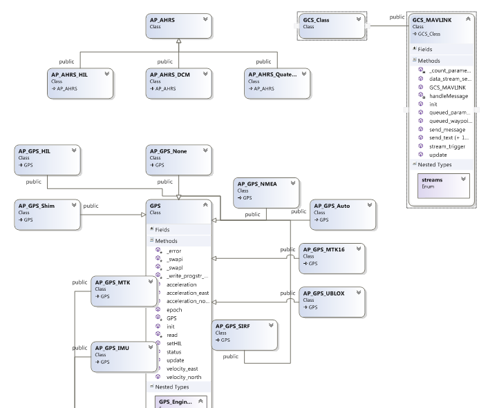
Reference
Microsoft Visual Studio provides a 100% compatible development environment for Arduino and Apm. It is also used to create the diydrones GCS. The Arduino plugin for Visual Studio is free and available from here, Visual Studio can be downloaded for free via here
If you're buying a premade quadcopter kit like ArduCopter, it will come with a PCB-based Power Distribution Board. But what if you're making your own? You either have to wire together your own harness or, like xnaron did here, make your own PCB. He did a great job of it, but this may be a bit beyond most people's reach: he has both a CNC laser engraver and PCB acid etching materials. But worth reading for tips, even if you don't have the gear.
(via Hackaday)
3DR ArduCopter kits are back in stock at the 3D Robotics store. The kits have gone through a slight redesign both in mechanical design and documentation. Our new facility in Tijuana, Mexico as well as better suppliers for parts have allowed us to greatly improve the quality of these kits as well as offering them for lower prices. The new frames also look stunning!
The main change to both of the kits is the new arms, the arms are now 40mm shorter which translates to about 10 grams lighter per arm. This allows for the motor cables to be shorter and reduce the weight of the vehicle overall. The motors are no longer mounted through the entire cross section of the arm which caused the old 3DR arms to sink, the motors are not mounted to the top face of the arm providing a better mounting surface. The two frames are significantly smaller and will allow for easier transportation. The arms now come in two colors, blue and black. Each kit will contain 2 blue arms and a spare black arm (3 black arms for the Quad kit and 5 black arms for the hexa kit), this will allow you to build your vehicle in either + or x configuration with the front indicated by a blue arm(s).The center plates on the Hexa-B have been redesigned to accommodate for the shorter arms and large props.
The manuals for both of the kits have been re-written, we took all your feedback and produced a better set of assembly and set-up instructions. 3DR will also be providing a parameter file for these specific frames and keep it current as the code evolves to provide the best possible performance with these frames. The first iteration of this param file should be available shortly.
The full flight electronics quad and hexa kit have been upgraded to APM2.5 .
3DR ArduCopter Quad-C
3DR ArduCopter Quad-C Frame Kit $99.99
3DR ArduCopter Quad-C Frame + Motors Kit $249.99
3DR ArduCopter Quad-C Frame + Motors + Full Flight Electronics Kit $449.99
3DR ArduCopter Hexa-B
3DR ArduCopter Hexa-B Frame Kit $129.99
3DR ArduCopter Hexa-B Frame + Motors Kit $349.99
3DR ArduCopter Hexa-B Frame + Motors + Full Flight Electronics Kit $549.99
3DR ArduCopter kits will begin shipping today!
Hi all, it appears that my blog post “Yaw Control, ESC Linearization, and Hover” has been lost. I hope that it will be saveable but I am not holding my breath. If it can’t be saved I will attempt to reconstruct it but while I have most people’s replies on my emails but I don’t have my own. If anybody has a copy of my replies I would be very grateful if you could send them to me.
The discussion that followed that blog post focused on the "stability patch" in AP_MotorsMatrix.cpp.
Both myself and R_Lefebvre attempted to explain this in detail in the blog post above so I won’t do it again now in a hope that we will get that work back (fingers crossed). But I will attempt to summarise the issues that we would like to address.
- Near maximum and minimum throttle the control is compromised because we can’t decrease propeller lift much further at minimum throttle or increase it much further maximum throttle.
- When multiple Roll, Pitch, and Yaw manoeuvres are happening, how do we combine these with the requested Throttle setting to maintain stability.
- Yaw control is very limited in most of the multi rotor geometries and therefore results in large RPM variation in motors compared to Roll and Pitch to create an equivalent Yaw response. The lift force generated tends to be non-linear creating an increase in lifting force when Yaw is applied. How can we correct this behaviour?
While addressing these points we need to ensure that:
- We maintain stability and preferably good control over Roll, Pitch, and Yaw.
- Throttle response and altitude control is not compromised any more than absolutely necessary.
- That we don’t do anything that can prevent an overpowered multi rotor from coming down!
Yaw Curve
Ok, easy bit first.
Yaw is achieved by increasing the RPM of half the motors and decreasing it in the other half of the motors. However, because the lift of a given propeller tends to increase by the square of the change in RPM, this results in an increased total lifting force.
Reference is page 16 here: http://dc-rc.org/pdf/Model%20Propellers%20Article.pdf
So what we want to do is increase the RPM of half the motors less than we decrease the RPM of the other half and keep it the same as when all motors are at the same RPM.
Ok, some maths.
x = RPM of all motors at stationary hover.
y = RPM reduction of half the motors during Yaw.
z = RPM increase of half the motors during Yaw.
Total lifting force at hover for a quad is:
Total Force = 4*x^2
When inducing a Yaw it is:
Total Force = 2*(x - y)^2 + 2*(x + z)^2
We want these two equations to be equal if we don’t want the quad to start accelerating vertically therefore:
4*x^2 = 2*(x - y)^2 + 2*(x + z)^2
2*x^2 = (x - y)^2 + (x + z)^2
2*x^2 = x^2 + y^2 -2*x*y + x^2 + z^2 + 2*x*z
2*x^2 = 2*x^2 + y^2 -2*x*y + z^2 + 2*x*z
0 = y^2 -2*x*y + z^2 + 2*x*z
0 = z^2 + 2*x*z + y^2 -2*x*y
if we solve this for z we get:
z = -x + sqrt(x^2 – y^2 + 2*x*y)
If we plot this we get:
The excel file I used is here if you would like to play with it.
The current ratio line is the ratio we are currently considering using, ie 0.7 up and 1.42 down. As you can see, the ratio starts off 1:1 then reduces to sqrt(2)-1 or 0.414. We could get pretty close to the ideal line using a straight line approximation:
z = 1 - (2-SQRT(2)) * x/y
This will give us a small increase in lift half way along but it is pretty close. Looking at the added complexity with this approach I think it is probably better to go with the constant ratio approach that is currently commented out in the code. This makes all calculations much quicker and easier.
Stability Patch
Ok, now the difficult bit.
The approach I suggested in the lost blog was
- calculate all motor settings for Roll, Pitch and Throttle.
- calculate the remaining headroom between these throttle settings and the max_throttle and min_throttle.
- if the headroom is not enough to contain the requested Yaw input the we reduce the requested Yaw to fit the available headroom or the minimum reserved yaw headroom.
- We then go through and add the Yaw request to each motor output with the throttle offset to ensure the outputs remain between the max_throttle setting and the min_throttle setting.
We do need to be very careful that Pitch or Yaw oscillations can’t make a high powered quad fly away though. I have some ideas on this but it may not be needed.
In the lost post the question was raised by Randy. “For example, I think it's much better to abandon a request from an autopilot for a 45 degree pitch forward in favour of maintaining yaw.” We could do this by:
- reducing the stick input travel at low or high throttle,
- reducing the limit on roll and pitch rate outputs at low or high throttle,
- or scaling the rate outputs in the MotorMatix function.
I don’t like any of these options because they either directly interfere with the users inputs or change the ability of the Rate_I (or Stab_I) term to do it job and correct for CG and motor output offsets.
The good news is that I don’t think this is a problem if we leave the Roll and Pitch components un touched. At near minimum throttle we are descending and we can get a large Roll or Pitch output from the Rate PID’s from two things:
- a large stick input from the user,
- a large exterior force.
Point 1. If the user enters a command to change attitude from horizontal to 45 degree pitch for example. With full Pitch control this will happen in less than a second (for my quad anyway). For this short time we may lose almost all our Yaw authority leaving just a little more than is required to maintain a heading. However, as the Pitch angle increases the throttle boost kicks in. This will dramatically increase the throttle setting restoring Yaw authority.
On the other hand, If the airframe is at 45 degrees and I let go of the sticks in stabilise mode. I want to see my copter go level as fast as possible. I don’t care if I lose all Yaw authority for a second provided my copter is level afterwards. Then with the small amount of Yaw authority that we keep in reserve the copter can change the heading as requested.
Point 2. If the copter experiences a large outside force… say clips a branch while descending to land, all I care about is that it gets up the right way again. As before, Throttle boost will help us here for a portion of the rotation, but Yaw is my absolute lowest priority.
Remember I am not advocating removing all Yaw authority, I am suggesting reserving only enough to maintain a heading and apply small Yaw accelerations.
Code Example
To quote R_Lefebvre from the lost blog post, “this isn't finished working code, just kind of a back-of-the-envelope sketch”
// capture desired roll, pitch, yaw and throttle from receiver
_rc_roll->calc_pwm();
_rc_pitch->calc_pwm();
_rc_throttle->calc_pwm();
_rc_yaw->calc_pwm();
// mix roll, pitch, throttle into output for each motor
for( i=0; i<AP_MOTORS_MAX_NUM_MOTORS; i++ ) {
if( motor_enabled[i] ) {
motor_out[i] = _rc_throttle->radio_out +
_rc_roll->pwm_out * _roll_factor[i] +
_rc_pitch->pwm_out * _pitch_factor[i];
}
}
// calulate the minium headroom left for Yaw.
high_yaw_pos = 1000;
high_yaw_neg = 1000;
low_yaw_pos = 1000;
low_yaw_neg = 1000;
high_throttle = 0;
low_throttle = 2000;
// the signs I have used might be wrong
for( i=0; i<AP_MOTORS_MAX_NUM_MOTORS; i++ ) {
if( motor_enabled[i]) {
if( _yaw_factor[i] > 0 ) {
if( high_yaw_pos > (out_max - motor_out[i])/ ) {
high_yaw_pos = out_max - motor_out[i];
}
if( low_yaw_neg > motor_out[i] - out_min ) {
low_yaw_neg = motor_out[i] - out_min;
}
} else if( _yaw_factor[i] < 0 ) {
if( high_yaw_neg > out_max - motor_out[i] ) {
high_yaw_neg = out_max - motor_out[i];
}
if( low_yaw_pos > motor_out[i] - out_min ) {
low_yaw_pos = motor_out[i] - out_min;
}
}
if( high_throttle < motor_out[i] ) {
high_throttle = motor_out[i];
}
if( low_throttle > motor_out[i] ) {
low_throttle = motor_out[i];
}
}
}
yaw_ratio = 0.7/1.42;
high_yaw_pos = max(high_yaw_pos, min_yaw_headroom);
high_yaw_neg = max(high_yaw_neg, min_yaw_headroom);
low_yaw_pos = max(low_yaw_pos, min_yaw_headroom);
low_yaw_neg = max(low_yaw_neg, min_yaw_headroom);
yaw_pos = min(high_yaw_pos/yaw_ratio, low_yaw_pos);
yaw_neg = min(high_yaw_neg/yaw_ratio, low_yaw_neg);
rc_yaw_pwm_out = constrain(_rc_yaw->pwm_out, -yaw_neg, yaw_pos);
min_required_yaw_headroom = min(reserved_yaw_headroom, rc_yaw->pwm_out);
if( (out_max-high_throttle)/yaw_ratio < (low_throttle - out_min) ) {
throttle_change = min((out_max-high_throttle) - min_yaw_headroom*yaw_ratio,0);
}else{
throttle_change = max((out_min-low_throttle) + min_yaw_headroom,0);
}
for( i=0; i<AP_MOTORS_MAX_NUM_MOTORS; i++ ) {
if( motor_enabled[i] ) {
yaw_contribution = rc_yaw_pwm_out*_yaw_factor[i];
if (yaw_contribution > 0 ){
yaw_contribution *= yaw_ratio;
}
motor_out[i] = motor_out[i] +
throttle_change +
yaw_contribution;
}
}
// ensure motors are not outside alowable region
for( i=0; i<AP_MOTORS_MAX_NUM_MOTORS; i++ ) {
if( motor_enabled[i] ) {
motor_out[i] = constrain(motor_out[i], out_min, out_max);
}
}