All Posts (14048)

Sort by

Wifi cam complete

Various modes of Marcy 2's fully functioning wifi camera are shown. A 168Mhz 128k RAM chip compresses JPEG & streams on 802.11g. As the frame size increases & color is enabled, the framerate goes down. Body movement around the antenna makes it drop packets. It still compresses a lot faster on 168Mhz & 128k RAM than a 166Mhz Cyrix with 64MB SDRAM did, 15 years ago. The Cyrix only did 5fps 320x240 color, if you were lucky.


With a new, unmelted camera finally arriving, the true frame rates & bit rates could be known.

640x480 color: 3fps    800 kbit
640x480 grey: 4fps    1 megabit
320x240 color: 20fps    2.5 megabit
320x240 grey: 30fps     3 megabit


Quite an improvement over the UART cams from Sparkfun.  The bitrate got a lot higher when the lens wasn't melted.  All the 640x480 modes had to go to single buffers to fit in the RAM.  They could double buffer if the quality was reduced way down.  Noise is now the real problem.  Capacitance directly on the wireless dongle is the key.  Networking bitrate is way up.  Bluetooth wouldn't be an option.


320x240.jpg

320x240c.jpg


640x480.jpg

640x480c.jpg


desolder01.jpg


Desoldering position for the melted cam.

cam81.jpg


Another $20 in Nate's retirement fund.

cam83.jpg


Another perfect soldering job.
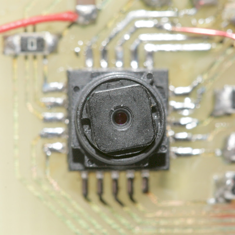
cam84.jpg


Marcy 2's eye.

marcy2_19.jpg

 The TCM8230MD does run on as low a clockspeed as you want, giving a much brighter picture & a data rate suitable for 8 bit micros.  The rolling shutter got bad at 1Mhz.  It's certainly no good for aerial photos at 1Mhz.  Rolling shutter is much less at 28Mhz.


It would be revealing to know how bad the AR drone cameras are, but the guys who use those don't know what a rolling shutter is.

For video compression, some research led back to rtjpeg, an ancient piece of code from the early days of video.  A guy spent a lot of time making the simplest, fastest DCT image compressor possible.  It's totally impractical for video editing on today's computers, but perfect for embedded microcontrollers.

A port of RTJPEG & a step up in optimization flags got the frame rate way up.  The trick was compressing the DMA buffers directly & doing the whole process from camera to network without any mem copies.  For greyscale, it compresses 8 lines at a time, as the frame is read from the camera.  For color, it compresses 16 lines at a time.  Thus only 128k RAM can compress 640x480 color.


The camera generates much less noise when underclocked below 4Mhz, but the rolling shutter is really bad.  The network is very prone to going down or dropping out during a high bitrate stream, since the chip doesn't have enough bandwidth to service ASSOC requests while streaming at full speed.  Pounding on the 'iwconfig essid Marcy2' command keeps it alive, but a phone can't be depended on to do that.

It's not every day such an original hack job suddenly spits out 30fps video, but the nominal bitrate in flight is only going to be 256kbit & that could have been done by bluetooth.  It would be a lot easier for users to get working & it has a lot more supported parts.

Getting the frames to align on the top row ended up requiring starting
the DMA 1st, the camera configuration 2nd, & the DCMI last.  There was no obvious way to synchronize the DMA with the VSYNC.  Perhaps the DCMI does some magic when DMA is already running.
Finally got around to stepping the wifi up to 54 megabits.  It uses a lot less power than 1 megabit.  The bitrate is actually set in the hardware dependent header for each packet.  MGMT frames get 1 megabit.  DATA frames get 54 megabits.
That makes the connection drop more frequently, but gets the bandwidth up to 4 megabits, in our beacon response protocol.  That's way above Roving Networks.

Consider the material cost: $14 for the ARM, $10 for the camera, $5 for the wifi card, $10 for the board & discrete parts.  The receiver is built into every laptop & it's a modern digital signal instead of the 15 year old analog everyone else is using, so it could be a viable alternative to an analog flight downlink.

propeller06.jpg

Discovered these 1mm shaft propellers can simply be pressed on the 1.5mm motor shaft. This is what everyone's doing, hence the lack of any prop adapter like what we've been using. Even the adapter was friction based.


 Marcy 2 now needs a huge cash infusion to continue.  Hobbyking has stopped restocking most everything that made it not Tower Hobbies, leaving only full priced versions.

The very 1st images received from Marcy 2's wifi camera.

Read more…

Introducing the SpyHawk FPV RTF

Pretty cool set-up and comes with everything you need including FPV TX with video screen and sun sheild.  More details available HERE


RTF Package Includes:

  • SpyHawk 4 Channel Mini Glider
  • Built in 5.8 Ghz FPV System w/Recording Module & 4GB SD Card
  • State of the Art 3 Axis Flight Stabilization System
  • 2.4Ghz Radio with Built in 5.8Ghz Video Receiver and High Resolution 3.5" Color LCD
  • 7.4v 450mAh Lipoly Battery & Balance Charger
  • Spare Propeller, User Manual & Glue
Read more…
3D Robotics

3689455644?profile=originalFrom IEEE Spectrum:

Quadrotors are famous for being able to pull all sorts of crazy stunts, but inevitably, somewhere in the background of the amazing video footage of said crazy stunts you'll notice the baleful red glow of a Vicon motion tracking system. Now, we don't want to call this cheating or anything, but we're certainly looking forward to the day when quadrotors can do this outside of a lab, and the sFly project is helping to make this happen.

What makes the sFly project, led by ETH Zurich's Autonomous Systems Lab, different is that the sFly quadrotors don't rely on motion capture systems. They also don't rely on GPS, remote control, radio beacons, laser rangefinders, frantically waving undergrads, or anything else. The only thing that sFly has to go on is an IMU and an onboard camera (and an integrated computer), but using just those systems (and a "very efficient onboard inertial-aided visual simultaneous localization and mapping algorithm"), sFly is capable of navigating all by itself. And if you have a fleet of sFly quadrotors, you can use them to make cooperative 3D maps of the environment:

Each quadrotor is completely autonomous, but they're also equipped with two extra cameras that stream stereo imagery back to a central computer over GSM or Wi-Fi that takes the data from several quadrotors and combines it into an overall 3D model of the environment as a whole. Then, the computer can guide each robot to an optimal surveillance site. The idea here is that you'd be able to rapidly deploy an sFly system with a swarm autonomous quadrotors in a disaster area or somewhere else without any infrastructure (or even a GPS signal) and still be able to take advantage of some clever autonomous aerial mapping.

Read more…
3D Robotics

Flapping bot can perch on a hand

From IEEE Spectrum:

There are lots of innovative ways of landing robotic aircraft, from cables to parachutes to controlled crashes. Arguably, none of these ways are ideal, with ideal referring to an aircraft that makes a gentle landing just exactly where you want it. Say, right on the back of your hand. 

Part of what makes this robot (under development at the Department of Aerospace Engineering at the University of Illinois at Urbana-Champaign) so cool is the fact that it uses flapping wings for extra maneuverability and, one has to assume, at least a little bit of thrust. This bio-inspired model (based on birds and bats) can reorient its wings while gliding, providing glide-phase control without a bunch of extra complicated and heavy actuators. It's highly effective control, too, and allows a thrown micro air vehicle (MAV) to make a pinpoint landing on the back of an outstretched hand:

Read more…

No kites near airports

3689455610?profile=original

Credit: Los Angeles County Sheriff’s Department

Under little-known federal regulations passed in 1963, moored balloons and kites cannot be flown within five miles of an airport or more than 500 feet off the ground.

FAR 101 is the regulation you need to know to maintain balloon compliance. SkyVector is a great online source for understanding sectionals (flight paths) for your airport code near you.

Read more…

3689455390?profile=original

I’m pleased to announce the release of the first major product from Event 38, model E382, a Ready to Fly Photomapping UAS. Based on the APM 2.0, the E382 is designed to make aerial maps quickly and easily for those not interested in cutting, gluing and programming a plane from the basic components.

Let me start with a little background about myself. I’ve been involved with DIY Drones since 2009 when I worked on a turn-rate-limiter style project for Arduplane. I then spent a year working at SpaceX before moving to San Diego to join 3D Robotics last March. Now I’ve started Event 38 to bring the usefulness of APM-based UAS to a wider audience.

The basic kit consists of a ready to fly Skywalker V5 (168cm wingspan, 190cm wingspan upgrade available) with APM 2.0, motor, ESC and servos installed. APM is preloaded with the latest Arduplane release and a known good configuration file. This set of components together lets you skip all the uncertainties that invariably pop up when starting such a complicated project and gets you to the first flight right away!

Equipped with a small point and shoot camera, the E382 can make extremely detailed high-level maps from individual pictures stitched together. Even 3d terrain models can be made really easily using free services like hypr3d and soon, DroneMapper.com. The image below was made with Hypr3d in about 25 minutes.

3689455181?profile=original


The fully built plane is available, to start, only in the US and Canada. Planes are in stock now and ready to ship immediately.

Check out the product page and please leave your comments on this thread, I’m eager to hear feedback from the DIY Drones community!

www.Event38.com

EDIT: See extra photos below:

3689455453?profile=original

3689455192?profile=original

3689455507?profile=original

3689455439?profile=original

3689455533?profile=original

Read more…

Full carbon frame with sexy color  , 6 ducted propellors, semi-waterproof, enough room for 4 5A 4s lipo's. maximum prop size is 12".
Props are fully protected, can bump into wall, tree, person, without breaking props or hurting people.

Empty weight is 3,7kg. Current set-up Axi 2804/22 and graupner 11x5" props. Still looking for a better combination though, for increased flight time. 

scaled.php?server=443&filename=img20120502113944xv.jpg&res=landing

scaled.php?server=844&filename=img20120502114002.jpg&res=landing

scaled.php?server=607&filename=img20120502114208.jpg&res=landing

Read more…

3689455372?profile=original

Scarlet Knight . . . The future of deep-water oceanography?

On December 9, officials from NOAA joined scientists from Rutgers University and other overseas institutions in a celebration highlighting the first-ever trans-Atlantic ocean crossing of an unmanned, underwater glider . . . 

The glider, launched off the coast of New Jersey last April, repeatedly dove to depths of 200 meters (656 feet) to collect data including temperature, salinity, and density. Scientists correlate these data with those from satellite imagery and altimetry, sea-floor and buoy-mounted sensors, and radar systems to get a more detailed view of a particular patch of ocean in near real time.

Source: NOAA's press release 

Further details about mission can be found at Rutgers University Scarlet Knight website.

Read more…
Moderator

3689455402?profile=original

First early Flight Video only for test that all work fine ... a windy day and need to setup PID because with more power the old one is not good:

Dear Friends,
i'm happy to inform you that our new product Multipilot32F4 and NAVY 2012 is ready
for beta testing for a special price of 199 euro.
We presented it at the beginning of year .We finish to port low
level library from STM32F1 to STM32F4: We rewrite old libmaple for STM32F1 by scratch porting
all lib to STM32F4. (thank's Alberto V for his work on library)
So the AP_LIB have same interface of standard AP_LIB for arduino and
the Arducopter32 is very similar to original revision for Arduino
platform , share 98% with original code.

Original Blog Post : http://www.virtualrobotix.com/profiles/blogs/vr-multipilot32f4-the-most-powerful-auto-pilot-in-the-world-compa

The firmware that i using in my fly test is Arducopter 2.5.4 so it's last available.

I'm doing my first fly test in these day with success . A video will be availabe in the next days

3689455363?profile=original

The characteristics of Multipilot32F4 are:

Hardware:

  • ARM Cortex-M4 processor STM32F407VET6. 168 Mhz
  • Flash 1024 Kbytes RAM 196 Kbytes
  • 16-bit Timer 4
  • SPI 2 (ADC Interface , MicroSD connection Option)
  • I ² C 2 (First I2C (sensor), Second I2C control until ESC 12)
  • USART 5 (GPS, DEBUG Console, XBee Pro Telemetry)
  • USB 1 (Upload Firmware, Debug Console, Power Board for Debug)
  • CAN 1 (Interconnection with Professional ESC 1 Mbit update rate)
  • 8 PWM Output Bit 16 (ESC / Servo Control)
  • 7 PWM Input 16 Bit (RC Input Channel, accept PPM SUM)
  • 8 Analog Input 12 Bit.
  • Professional 4 layers PCB.
  • DC: DC 30 V (6s Lipo): 5 volts and 3.3 volts
  • MPU6000 Imu Sensor 3 gyro and 3 acc on board

The NAVY 2012

  • HMC5883 3 axis magnetic sensor
  • EEPROM for data storage
  • MS6511 high precision barometer
  • MTEK GPS with custom firmware for arducopter.
  • Dataflash on board.
  • SDIO SD Card
  • SPI SD Card that support FAT file systems. (Optional)


More info about the boards are available here :

http://www.virtualrobotix.com/page/multipilot32f4-v3-0
The board is yet in production and available the next stock could be
available in the middle of may.

There are a lot of tool for development :

  • A very light toolchain for peolpe that like command line ... a lot in hard developer community.
  • A VRIDE Pro that is an eclipse with support for JTAG debugging .. we using ST-LINK.
  • An VRIDE Std that will be available in some week for end user .

Is possible to use the DFU on usb for upgrade firmware without problem.
This is the link for download last revision of enviroment :http://code.google.com/p/multipilot32/downloads/detail?name=VR%20MP32F4%20%20IDE%20LIB%20FIRMWARE%2001-5-2012%202.6%20%20beta.rar&can=2&q=#makechanges


This is the link of the thread on virtualrobotix forum:
http://www.virtualrobotix.com/forum/topics/multipilot32-v3-f1-f4-and-new-vr-ide-pro


In our test we found more of 12x respect to standard Arduino Mega hardware platform.

The spare time cicle in 5 second is 3610 for APM and 42321 for an Multipilo32F4.

In this test is not yet available the FPU acceleration only by different clock 16 mhz for arduino , 168 for Multipilot32F4

In this video you can see the different whe use FPU ON or FPU OFF math acceleragion going up 17x


This is the new benchmark
Arduino APM1 e APM2
PerfMon: cpu% mils #called Hz
loop 33.45% 96 3614 0hz
read_AHR 34.09% 98 29 0hz
FiftyHZ_Loop 2.88% 8 15 0hz
Update_GPS 0.56% 1 15 0hz
setupA 0.00% 0 0 0hz
unexplained 29.03% 83

STM32F1 MP32F1
PerfMon: cpu% mils #called Hz
loop 35.81% 112 18357 0hz
read_AHR 23.53% 73 130 0hz Fif y
FiftyHZ_Loop H 7.54 54 15 0hz
SuperFast_Loop 3.04% 9 392 0hz
Update_GPS 1.10% 3 15 0hz
ReadBarometer 0.07% 0 3 0hz
setupA 0.00% 0 0 0hz
unexplained 18.91% 59

STM32F4 MP32F4 ( NOW I2C IS OK )
PerfMon: cpu% mils #called Hz
loop 46.88% 131 42321 0hz
read_AHR 11.01% 30 138 0hz
SuperFast_Loop 8.45% 23 519 0hz
FiftyHZ_Loop 3.00% 8 15 0hz
Update_GPS 0.13% 0 15 0hz
ReadBarometer 0.04% 0 3 0hz
setupA 0.00% 0 0 0hz
unexplained 30.49% 85


So if someone would join the development is welcome :)

Best

Roberto Navoni

Read more…
Developer

[UPDATE: This project is now being ported to a proper Google Code repository and manual. For instructions, start there. You can also join the ArduRover User Group here.]

Hello to ALL, the new firmware for APMRover v2 has been tested successfully on my rover on may 1st, 2012 on full autonomous reco mission following a navigation plan. This new release of the APMRover v2 works on the APM v1.4 with the OilPan shield (magnetometer + MT3329 GPS) and also of course on the APM v2. The previous version of the APMRover v1.0 was a light size version specially designed for the APM1280 CPU (only) board and the MT3329 GPS.

3689454489?profile=original

For the frame, I have used a Traxxas Monster Jam Grinder with a brushed and high power motor Titan 12T and its XL-5 ESC.

The APMrover UGV is able to run itself following a list of recorded waypoints. The waypoints list (FPL) can be preloaded with the APM Mission Planner OR better in live, recorded by the pilot himself (with the SW7) during a manual run and then replayed in a full autonomous mission.

3689454514?profile=original

3689454602?profile=original

3689454577?profile=original

3689454598?profile=original

The firmware APMrover2 for APM v1 + OilPan or APM v2 successfully tested can be downloaded HERE

The APMrover v2 is also online on the official ArduPilot-Mega GIT repository HERE

Below the PID setup for the APMrover v1 and v2:

3689454536?profile=original

The light firmware APMrover1 for APM v1 (CPU 1280 or 2560) that I have tested can be downloaded HERE 

Here's how to connect your cables:

3689454662?profile=original

More infos at: http://diydrones.com/profile/JeanLouisNaudin

Have Fun and Enjoy with the APMrover...

Regards, Jean-Louis

Read more…

Just posted photos and video of my Skywalker.  After the third(last) flight, the fuselage is a write off.  Lots of work went into it.  On the brighter side, the only electronic (expensive) item damaged was the $30 video camera for the video downlink.  The ContourHD camera in the nose not only captured great HD video but also survived the crash (actually two crashes, two deployments to Afghanistan and the Warrior Dash on Saturday).

Read more…
Developer

Confessions of a gadget addict...

3689455337?profile=original

I am probably going to get hate mail for this, but a clear warning to any future addicts needs to be made. So here goes.

I was doing some spring cleaning and those darn DIY gadgets just kept on coming out of the woodwork. I knew I had a lot of stuff lying around, but this time I even surprised myself. And this is just DIY/FPV/Autopilot electronics currently not installed in a project. I will not show the pile of unfinished projects like copters, planes, rovers etc. It's just embarrassing. And the is also a big pile of general R/C stuff like ESC's motors, servos,  gyros, receivers and such..

Anyways, there should be some well knows gadgets in this picture, and some not so well known ones also. Geek points to the first one to correctly identify them all, excluding the self made stuff that only I would know of.

Morale of the story? Get bigger storage boxes I guess..

Read more…
T3

3689455144?profile=original

Team,

I have recently performed flight tests on a major change in the way acceleration is accounted for in performing roll-pitch drift compensation from accelerometer measurements. The theory behind the idea was recently published in a discussion on this website. Since then, I have made a couple of refinements to the idea, the latest version is documented here.

Implementation in MatrixPilot is shown here. There is one slight "tweak" in the implementation that is not covered in the theory paper: although in principle the new method can provide yaw drift information, in the implementation I have used it for roll and pitch only.

I put off posting a blog entry until I had flight test data, which I now have. The above picture is from one of several recent test flights with a UAVDevBoard running MatrixPilot on an EasyStar, that shows that the idea works. What is shown is a comparison of the GPS track and the "dead-reckoning" computation. The yellow arrows indicate the wind direction and the plane icons indicate the attitude of the plane. The fact that the two tracks match rather closely is an indication that the estimated attitude matches the actual attitude, otherwise there would be a large discrepancy.

A major advantage of the new method is that it does not require a model for computing aerodynamic forces, nor does it make any of the approximations that previous methods do. It is based on kinematics only, and does not make any approximations. Therefore, it will provide accurate acceleration compensation for any platform, including quads, cars, motorcycles, baseballs, anything you want to attach an IMU to. (For anything but fixed wing, it does require a magnetometer.)

Now, some more pictures.

The next picture is taken from a portion of the flight in which the EasyStar flew in a tight circle for several minutes. Both GPS and dead-reckoning tracks are plotted. Two out of many revolutions are shown. It is during circling flight that it is particularly critical that acceleration be correctly accounted for. As can be seen, GPS and dead-reckoning match, indicating that attitude estimate is correct.

3689455315?profile=original

The final picture is the track of the entire 20 minutes of one of the test flights, in which I did my best to "break" the algorithm.

3689455256?profile=original

Best regards,

Bill

Read more…

Pigeon Post Smart Case Update

Smart%20Case%20Gif%200.2.0.gif?__SQUARESPACE_CACHEVERSION=1335794321079&width=250

Following on from the Tacocopter post I thought I'd update you on the Pigeon Post Smart Case design.

So I received some feedback from the last version (V 0.1.4) and have added it to my own thoughts.  The improvements fall into 3 main areas:

1.  Make it omnidirectional.  Basically the gripper on the UAV needs to be able to grip the top plate from any direction on the horizontal plane.  The base also needs to have a gripper so the case can be lifted easily if the case is upside down. 

2.  Add guides.  There needs to be physical aspects of the Case to guide the case into the Coop and the Quadcopter gripper onto the top centre of the Case.  Although these may be limited seeing that any sloping part can only be 10mm deep, the more the better.

3. Remove all moving parts.  The swinging up T bar of Version 0.1.4 was a huge point of failure and needs to be replaced with a single solid part.

Incorporating these changes actually made the Smart Case much easier to standardise, easier to manufacture and lighter.  I've actually redesigned it from the base plate up so have changed the version number to 0.2.1.

Here's an overview of the design:

For ease of storage this version can be manufactured to fold flat and stack on top of each other.  The most compact way is to make a case which can compact down into the 1cm base and top plates and stacked on top of each other.  This means that 15 compacted cases can be stored in the space of standard case.

You can download the model here: Download Smart Case V 0.2.1

And a the model I used for the Gif above: Download Smart Case V 0.2.1 Display

I'll also put the design in the Google SketchUp library and post some photos of the 3D printed version as soon as I receive it.


Read more…
3D Robotics

Tacocopter flies! (sorta)

3689455224?profile=originalStar Simpson, the MIT grad who started the Tacocopter site/stunt, has been living in Hong Kong and she's decided to build on the media attention by actually working on a copter. As the Huffington Report puts it:

Well, the flight was more symbolic than anything, proof to the doubters that a small drone copter could indeed be rigged to handle the weight of a taco and the mission of taco delivery. As Simpson told HuffPost in March, Tacocopter is more of a concept than a concrete startup at this point, more a conversation starter about the future of delivery services than a realistic plan.

(Frankly, if we're getting pessimistic about Tacocopter's maiden flight, I'm more concerned with the taco itself: I like my tacos substantially -- substantially! -- larger than the one shown in the video. We want a tacocopter, not a taquitocopter).

So, no, Tacocopter isn't quite ready to scale up into a true company that mass delivers Mexican food via drone. It still has to learn to deal with an intimidating set of technical issues -- GPS mastery, mass production of drones, wind, heavy rain, birds, building ledges, telephone wires, thieves etc. -- before you can even think about actually receiving your taco via aerial flavor strike.

Here's the first flight:

Read more…
3D Robotics

3689454999?profile=originalI just got the Walkera QR Ladybird nanoquad and it's just frankly amazing. For $140, you get the quad, a 7 Channel 2.4 digital Devo 7 RC set with graphic backlit LCD display, a 240MaH LiPo and a LipPo charger. It can fly inside and out and has much better range than a Parrot AR.Drone (thanks to the proper RC gear). The RC gear alone is worth nearly that price (you can buy additional receivers for it here)!

Walkera says that it includes RC telemetry for battery and flight controller status:

1). Onboard telemetry system enables real-time monitoring of receiver, gyro, mix control and speed setting.
2). In-built telemetry function also enables and simplifies flight battery voltage monitoring.

We had a great time flying it around the living room. It's very stable, but as you would expect from a quad, very maneuverable. The transmitter starts up in regular mode (not dual rate or exponential, both of which are options), so it requires a very light touch on the sticks. A couple clicks of the trim and it will stay in one place. Because it moves fast and is so small, it's pretty easy to lose control in a small space, but the airframe seems quite robust. We crashed it lots of times, and just had to superglue on one of the motor holders after it cracked. Good as new!

3689454927?profile=original

Here are some shots of the incredible integration on the single flight controller board. It says it has a "six-axis gyro", but I think that must be a mis-translation from Chinese. It's probably a three-axis gyro and a three-axis accelerometer. Alternatively, it could just have a three-axis gyro, like the simple KK boards (in which case I don't know that the other three axes are supposed to be)

Top of the board, showing the flight computer and RC receiver

3689455030?profile=original

Bottom of the board, showing the motor controller microprocessors and four speed controller circuits.

3689454940?profile=original

Here's how the LiPo fits on the bottom:

3689455072?profile=original

A sense of the RC transmitter display

3689455111?profile=original

And a video in flight:

Read more…

APM 2.0 Attitude Accuracy

3689455203?profile=original

I am wondering if anybody has been able to do any sort of characterization of the attitude estimation accuracy of the APM 2.0. I asked on the Blog Post 'Great lecture on the Outback Challenge by APM developer Andrew Tridgell' what type of direct geo-referencing accuracy he was getting and he said "20m error at 100m altitude in our testing so far." If one were to assume all the error was from angular uncertainty in a single axis, this would suggest a number in the realm of 11 degrees of error. This is one case, and I know there are a lot of contributing factors for direct geo-referencing error but these are only numbers I could find so far. Does anybody else have insight on what one could expect? Are there any special calibration or alignment steps taken at the 3DR factory?

Read more…
3D Robotics

Andrew Hazelden has a cool project!

This is a concept design for a handheld air traffic control system for model airplanes. This project is designed to allow a small handheld device to track the flight path of multiple model airplanes at a flying field. The mikroATC firmware can display either a vector map or aerial mosaic image tiles of the flying site. You can navigate the map view using the controlpad buttons.

In the YouTube video the flight pattern shown was created by the built-in mikroATC simulator routine.

The display code supports tracking multiple model airplanes at the same time. Each model airplane that is tracked has its own unique ID, display name, and telemetry struct data. This demo is powered by a MikroElektronika MMB board with a Microchip dsPic33 P33FJ256GP710A MCU and the mikromedia gaming shield.

(via RCG)

Read more…