John Morgan's nanocopter, which he's doing for this university research project, is coming along nicely! MPU-6050 sensors, MultiWII code,
All Posts (14048)
Sort by
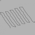
2012-04-23 at 19PM GMT+1, FLEXIPILOT (my own closed-source development) with special Terrain Follower firmware, controlling EasyUAV, has made its first long duration loiter at 1.5-3m AGL above sloped terrain. Loiter diameter was around 110m.
10m Flight took place in steady weather, while norhtern part of the field was 4-5m higher than southern part of the loop.
The autopilot exploited 3.5m of this range, maintaining reliably airplane altitude above uneven field borders. The barometric pressure, exhibiting usual long-term drift during 8min loiter, has confirmed aggressive altitude changes spanning 4m once autopilot flew into ground proximity zone.
Sensors used is a mixture of specific optical and ultrasound sensor, modified by me.
The effect of brutal pitch changes has destabilised flight speed, slightly 'smearing' the flight track.
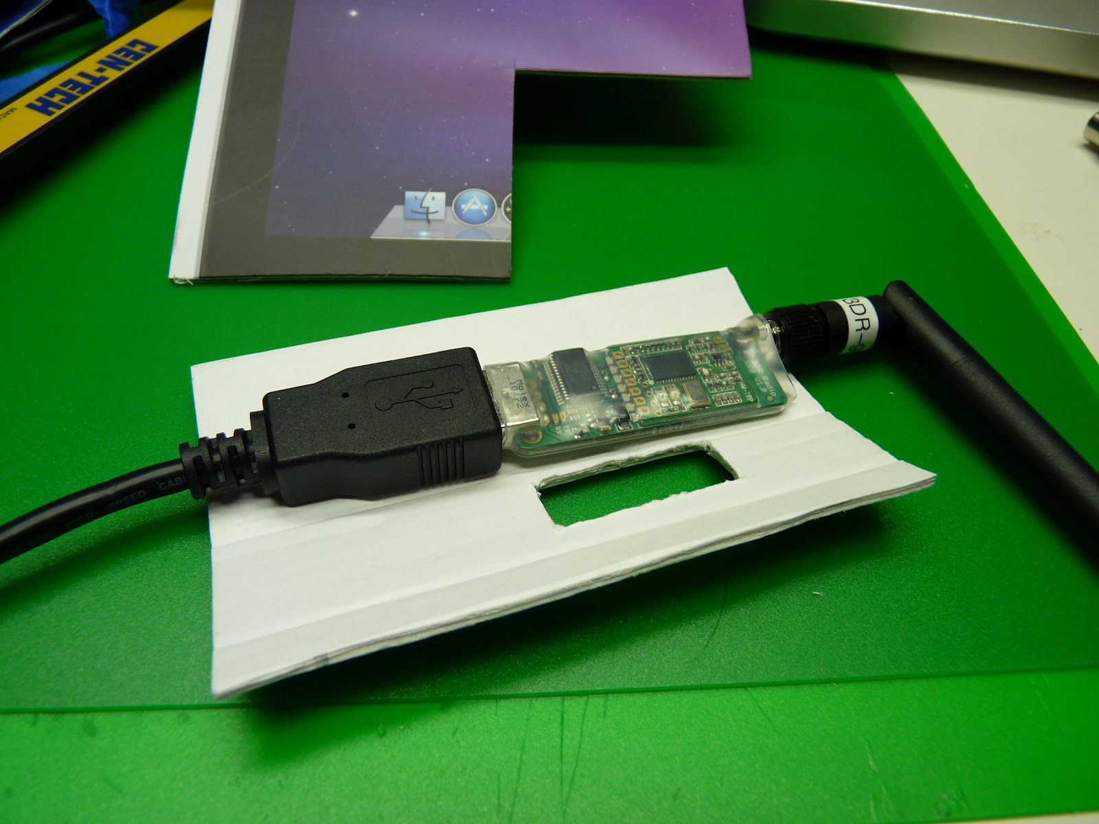
Prompted by Andreas M. Antonopoulos' comment regarding the possibility of breaking off the USB connector, I made a strain relieving case that also makes it easy to conveniently mount the module on the back of my laptop.
Details here:
http://eastbay-rc.blogspot.com/2012/04/strain-relief-carrier-for-3dr-ground.html

After a lot of fussing, finally got an 802.11 association.

That was a lot of work. Nothing changed. With 1 dongle, it only associates by doing iwlist manually, then iwconfig. With another dongle, it usually gets it with just the iwconfig command. The STM32 USB is still putting out a huge number of errors. The way iwconfig probes is always generating an error URB.
It turned out none of the current routers send beacons at all. What the kernel reports as beacons are really the responses to the last PROBE request.
STM32 bugs continued to torment. This time, the transmit operation ended up requiring multiple 64 byte packets. The demo showed multiple packets of 512 bytes. The receive operation allows any size buffer.
Also not in the demo, between transmit operations, you need a polling loop which waits for the urb status to not equal IDLE. Not equalling IDLE actually means it is idle. No receive or transmit operation can occur until the urb is not IDLE. Of course, the urb status is always IDLE before the 1st send request.
Those discoveries got Marcy 2 networking to stop locking up.
Networking got to the minimum level for a camera test. It does 0-800kbit/sec with lots of packet loss. This is using the ground station to send beacons & the aircraft to send 1024 bytes per beacon, all UDP, just like the final product. It would be much more complicated to have the aircraft send continuously. There isn't enough memory or latency tolerance to use TCP.
Networking got to the minimum level for a camera test. It does 0-800kbit/sec with lots of packet loss. This is using the ground station to send beacons & the aircraft to send 1024 bytes per beacon, all UDP, just like the final product. It would be much more complicated to have the aircraft send continuously. There isn't enough memory or latency tolerance to use TCP.
The 802.11 auth, assoc, & UDP packet generation are just good enough to work, even with the USB packet loss. The ARP table & DHCP is still manual. The hope is moving ahead will show more aspects of the latest USB problem.
Power consumption is a real problem. The DPAK LM317 starts smoking during 800kbit transmission, with no camera. A simple camera board obviously requires a lot of power hardware.

The board & camera were finally mated. Because Vdd appears in the same place on 3 of the corners, pin 1 ended up soldered wrong, which resulted in a hot air heating.

That melted it. Eventually heat it from behind & got it to fall off. The focus ring is now welded into place. The 1st pictures will be blurry, but hopefully good enough to characterize the rolling shutter.
This was the only part that only got 1 order, due to lack of money. This shows how the actual cost is much higher than the BOM.
Like any lens, it's not attached by much, & trying to turn a melted focus ring only rips off the lens.

Definitely some evidence of the focus ring melting all the way through.


The problem with these cameras is not the sensor as much as getting a sensor & lens combination in that size. Sensors are abundant. Could even use a CCD sensor & be done with warping, if the lens materialized.
Stupidly I left the props on while preparing a demo of one of my kk quads. The board malfunctioned while disarmed, props shattered and sliced most of the pad of my pinky finger right off. It took a trip to the hospital and 13 stitches to get it back on.
Finger 4 stitches in (Not for the faint of heart)
PSA: ALWAYS REMOVE PROPS WHILE TESTING AND NEVER USE BROKEN PROPS
We all saw the map generated with COA sites in the USA last week, thought it might be fun to have a map of our own.
There were only 60 or so sites that the FAA had, perhaps there are more private UAS flying around and about please feel free to add yourself! Not just in America but anywhere.
View Civil Unmanned Aircraft Research the sUAS News iFLY map.
ArduCopter now has experimental geo-fencing support, thanks to Andrew Tridgell's superb geo-fencing code for ArduPlane.
If you haven't heard of the geo-fencing features of ArduPlane, you are probably an ArduCopter user! Since December 2011, ArduPlane piltos have had the ability to build a virtual fence around an area and prohibit the aircraft from exit from the fence.
The details are in the GeoFencing wiki page.
So, now, this amazing feature is available for early-stage testing in ArduCopter.
Why do I want geo-fencing?
All four of my quad crashes follow the same scenario: pilot error causes the quad to go a bit far. Attempts to bring it back make the situation worse. The quad gets caught by wind or moves too fast and starts getting away from the pilot and out -of-sight. Eventually, you have to force a crash by killing the motors while you can still see the quad.
Runaway Copter - no more
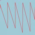
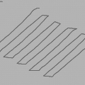
The images above show a software-in-the-loop simulation of Tridge's geo-fencing in action. The quad starts in the center of a large sports field, with a fence defined in a 50m radius around the center. A minimum altitude of 20m and a maximum altitude of 100m are set for the quad.
In the simulation, the quad's throttle is turned up to 75% and left at that level. Then pitch is set to a very aggressive 20-deg forward angle.
After liftoff, and once past the minimum altitude of the fence (20m), the fence is turned on by a switch on CH7 (preset in code).
The quad shoots straight up and right past the max altitude, because it has a lot of upward momentum. The fence triggers and switches the quad to guided mode to pull it back to the center (which is halfway altitude 100m-20m = 80m, and the point in the center of the fenced area). Because the throttle is still very high, the guided mode is able to stop it from climbing but can't quite pull it down. Easing off the throttle to about 45% makes the quad a bit more "tame".
The quad then spends the next five hours screaming at 25m/s speeds towards the walls, while hovering just under the ceiling (at an average of 98m) and bouncing back and forth. The shape that is created makes the fence visible.
Bottom line: Your quad cannot get away.
Get the code - Testing the geo-fence on ArduCopter (Experienced Coders)
As an experimental feature, you will need to be able to compile and upload code to the board without the Mission Planner (ie using Arduino IDE or command line). You will also need to (possibly) tweak some parameters to your liking.
Get the code using one of the following options:
- GIT - git checkout -b geofence_arducopter --track origin/geofence_arducopter
or
- Patch - see geofence-arducopter.diff, patch on "latest" ardupilot-mega source (circa Apr 25).
Compile and install!
Get the code - Testing the geo-fence on ArduCopter (for Adventurous Beginners)
A bit easier, you will still need to know how to upload code to the board
- Download and flash this ArduCopter.hex file
Use the geo-fencing in a flight
To test the geo-fencing for ArduCopter, it is easiest to use the default parameters. You can build a fence as with ArduPlane using Mission Planner to define the coordinates of the fence (any size closed polygon).
The other default parameters are defined in APM_Config.h with this code at the end of the file:
#define GEOFENCE_ENABLED ENABLED
#define FENCE_CHANNEL 7
#define RESET_SWITCH_CHAN 8
#define FENCE_ACTION FENCE_ACTION_GUIDED
#define FENCE_MINALT 20
#define FENCE_MAXALT 100 // meters
You can either tweak these in the code, or send them as MAVlink parameters I believe (not tested)
Automatic Fence
The new ArduCopter geo-fencing has one addition on the original ArduPlane code - the auto-fence! With automatic fencing, the code will create a 100m fence around your current location
If you have enabled geofencing (in the code) but have not defined the fence coordinates, the code will build a fence for you. You will need to have a GPS lock (reboot the board once you get a GPS lock) for this to work.
The FENCE_MAXALT is used to define the ceiling AND the diameter of the fence. So with FENCE_MAXALT at 100 meters, the default fence will be 100m wide, 100m tall. It is defined as an 18-sided polygon, with the center at the location you started (just like RTL, I believe) and the points defined at 20-degree intervals from 50m due north of your position, clockwise around your quad in a full circle (decaoctagon, more accurately). It looks like this:
You can tweak these parameters at startup, through Mission Planner or another MAVLink GCS. You can also use Mission Planner to define the geo-fencing points, just like in ArduPlane (have not tried this yet). See the ArduPlane geo-fencing instructions for more detail
Many many thanks to Andrew Tridgell for the superb geo-fencing idea and code.
Go forth, test and enjoy. Please give me feedback for the testing and development.
Andreas
http://www.MyGeekShow.com
On this week's episode of MyGeekShow we announce and begin building the Shrike, a Nova & Raptor hybrid. It's function will be to carry the AP and FPV equipment we'll install and test over the next few months. And yes, that includes the APM!
Next week we'll finish and fly the Shrike!
Question of the day: How do you seal XPS foam? We'd like some kind of "plastic paint" that was like painted packing tape, if that even exists.
See you Wednesday,
-Trent & Nick
Produced by Trent & Nick in Arkansas, USA
Main Camera: Panasonic HDC-TM900K
Video Editing: iMovie
I have posted this up on various posts but thought I would add it here for reference. I have found the same basic param file works on these two Micro Quads and should give you a decent starting point.
Both quads use-
APM 1-
1811 2900KV
5 X 3 Propellers
For APM 2 further PID reductions are necessary but not much.
From the Instructable:
Main Features:
- X mode flying
- MPU-6000 gyro & accelerometer sensor for flight stabilization
- USB battery recharging on the transmitter, the copter plugs into the transmitter to recharge
- When the copter plugs into the transmitter, the user can synchronize to a random radio frequency
- Controlled using a Wii Classic Controller, which plugs into the transmitter
- Running a modified MultiWii firmware, which is open source, written with Arduino and Processing
Dimension Specs:
- Square center body is 1.5" by 1.5"
- Propellers are about 45mm in diameter
- Diagonal motor to motor distance is 110mm
- Motors are supposedly "X-Twin" spare motors, they come with the propellers
Electrical Specs:
- Flight battery is a single Li-poly cell, 3.7V, 350mAH, 20C
- Controller battery is a single Li-ion cell, 3.7V, 1000mAH
- Uses ATmega128RFA1 microcontroller for both copter and transmitter
- This particular ATmega has a built-in 2.4GHz transceiver, 16 possible channels, 250kbit/s or 2mbit/s max depending on the standard being used.
Design Highlights:
- The "arms" and "body" are connected by locking slots, making them easy to build and repair
- Motors slide right into the arm
- Two layer 1.6mm thick FR4 PCB used (this is the default for a lot of PCB manufactures), the components are all on a single side (easy to assemble)
- All open source project, schematics + PCB + code all available. Heavy use of Arduino and Zigduino involved.
 The ArduEye prototype (left) and the finished sensor (right)
In a previous post, I demonstrated that the ArduEye platform could be used to prototype a 6DOF vision system for optical flow odometry. The goal is to make a vision system for the Harvard University Robobees Project.
After the success of the prototype, the next step was to design a board that was as small and light as possible. The result is shown below:
 Main components of vision system
The vision s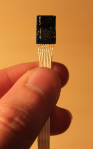 ystem consists of two back-to-back Stonyman vision chips, an Atmel ATMEGA 328P microcontroller, an oscillator (16Mhz), and a voltage regulator. The chips have flat printed optics (as described previously) with slits in order to take one-dimensional images of the environment. Even better, the Atmel has the Arduino bootloader, so the sensor is an Arduino clone and can be programmed through the Arduino IDE. The entire system weighs approximately 300-350 milligrams and has dimensions of 8x11 millimeters.
The following video shows that motion along all six axes can be distinguished. Some axes are stronger than others, and the Y translation, in particular, is weak. However, the results are promising and with a little optimization this could be a useful addition to a sensor suite.
I'd like to gauge the interest for an integrated Arduino clone vision sensor similar to this, but maybe not as compact and minimal. This would be most likely a one-sided vision chip with optics and an Arduino clone processor integrated on a small, single board. The size would be about that of a penny and weigh a half a gram. The user would have control over which pixels are read and how they are processed through the Arduino environment.

Some excerpts:
"Birds are famously good navigators. Some migrate thousands of miles, flying day and night, even when the stars are obscured. And for decades, scientists have known that one navigational skill they employ is an ability to detect variations in the earth’s magnetic field. How this magnetic sense works, however, has been frustratingly difficult to figure out."
"Navigating by magnetism includes several steps. Birds have to have a way to detect a magnetic field, and some part of the brain has to register that information; it seems likely that another part of the brain then compares the incoming information to a stored map."
“It’s a stunning piece of work,” David Keays of the Institute of Molecular Pathology in Vienna wrote in an e-mail. “Wu and Dickman have found cells in the pigeon brain that are tuned to specific directions of the magnetic field.”
As Dr. Lohmann said, the discovery “will no doubt inspire much additional work in the future.”
On this week's episode of MyGeekShow we flew the Raptor and Nova, at the same time! The Nova flew great and has totally restored our faith in the "traditional" airframe setup. The Raptor flew good as well, however the prop fell off and got lost in the tall grass somewhere. How do you prevent that from happening?
Tell us what you think of the new format!
-Trent & Nick
Produced by Trent & Nick in Arkansas, USA
Main Camera: Panasonic HDC-TM900K
Video Editing: iMovie
--Raptor--
Battery: 20C 2.2Ah Sky http://www.hobbypartz.com/77p-sl2200-3s1p-20c-3333.html
Servos: T-Pro 9G http://www.hobbypartz.com/topromisesg9.html
Motor: Optima 450 2220-1800KV
http://www.hobbypartz.com/75m55-optima450-2220-1800kv-2.html
ESC: Exceed RC Proton 30A http://www.hobbypartz.com/07e04-proton-30a.html
Prop: http://www3.towerhobbies.com/cgi-bin/wti0001p?&I=LXZL07
--Nova--
Battery: http://www.hobbypartz.com/77p-sl4400-3s1p-30c-3333.htmlidProduct=6306
Servos: http://www.hobbypartz.com/topromisesg9.html
Motor: http://www.hobbypartz.com/75m42-optima450-2220-950kv.html
ESC: http://www.hobbyking.com/hobbyking/store/uh_viewItem.asp?idProduct=13429
Prop: http://www.hobbyking.com/hobbyking/store/uh_viewItem.asp?idproduct=5437
Perth, Western Australia. COPTERCAM is cleared for take off after being issued with an UAV Operator Certificate from the Civil Aviation Safety Authority (CASA).
COPTERCAM becomes the first operator of the Droidworx multicopter airframe and Photohigher camera gimbal to be award an operator certificate (OC) from any civil aviation authority in the world. Obtaining government approval to operate a UAV in urban areas was quite a task, undertaken over a 9 month period and requiring thorough assessment by CASA.
COPTERCAM founder, Mr Hai Tran said: "After observing a number of illegal operators flying their drones with disregard to public safety and privacy, we share the concerns raised by civil liberties group. Commercial operators must be held to a higher standard of care because they owe it to their clients and the public, whose privacy and safety may be put at risk. Our OC application went pretty smoothly because all our UAV pilots also hold a Private Pilot Licence at a minimum. This allows us to share the airspace with real aircraft and ensures that our pilots have the right mindset about aviation safety".
Summer 2011,
I Have A Dream: See flying my Drone from it Antarctica.
Dream of the meeting of timeless nature and technology.
I designed for that a Drone, equipped with a APM1 (Thank you DIYDrones).
March 2012,
I was on the Antarctica Peninsula,
As in my dream, my Drone fly….
Feature:
Engine and ESC: HobbyKing
Electronic: APM1 + Original Motherboard (Alim and Elec distribution)
Frame: Original Design, All with carbon fiber.
RC : WBCommander = Original Design, Action Direct by Telemetry ( XBee-Pro 2.4GHz).
So, over the Easter weekend I had some time in the lab and threw together a crude repeating egg dropper for the quad. Of course, keeping me in line and the cops at bay, the other half talked me out of my nefarious plan to deliver raw, yolked goodies from above and instead had me whip up a tennis ball dropper to entertain the dog.
I've seen a lot of questions about manipulating servos with APM to either click the shutter on a camera or squeeze an airsoft trigger, so here's my approach using the USERHOOKS available in AC2.
Really simply, add the following code to UserCode.pde :
void userhook_init()
{
APM_RC.enable_out(CH_7); //Initialize CH_7 port for output
}void userhook_50Hz()
{
APM_RC.OutputCh(CH_7, APM_RC.InputCh(CH_6)); //Take input from CH_6 and output to CH_7
}
I think the comments make this pretty self explanatory. Monitor input CH_6 at 50Hz (50Hz is probably not necessary, but that function is already defined active in APM_Config.pde) and send that PWM straight out to output CH_7. After adjusting the endpoints on the radio to suit the required throws of the hardware, it was straight egg/tennis ball dropping fun!Be good.
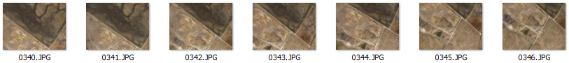
 How to get good results on your mapping mission with any backend processing service!
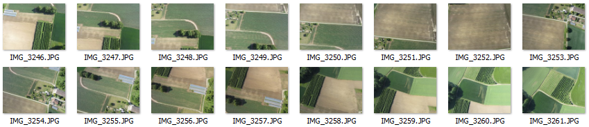
- Imagery should have at least 60% overlap and should have at least 20% orthogonal overlap.
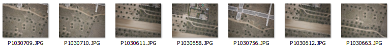
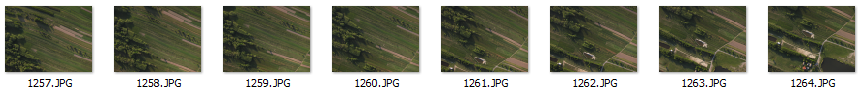
- Imagery must be shot in sequence. See examples below.
- Images must contain required EXIF information. [more]
- Images are shot with one camera and focal length.
- Images should not be pre-processed. (i.e. Lightroom, Picassa, etc)
- Images are NADIR or near vertical.
- Flight Path should be Parallel Line (aka Lawn Mower) or other large overlapping style.
- Flight Path should provide sufficient coverage of survey area. Meaning a large amount of overlapping images for target area.
- Flight should be from sufficient elevation. (i.e. >80 meters)
- Try a small subset of your imagery as a test. We process 15 images or less for free!
Flight Mode / Geolocation Guidelines:
- Use a supported Flight Controller with supported export format. [more]
- Sync your camera internal time with your flight controller GPS time. [more]
- Imagery EXIF timestamps must match flight controller log timestamps to obtain rough georeference.
- Flight Controller log exports should be in WGS84 for Latitude and Longitude. Elevation in (m) above the earths surface or actual elevation of image. Camera direction in (d).
- Each image must have a matching GPS/IMU log entry.
Imagery Sequences with Problems:
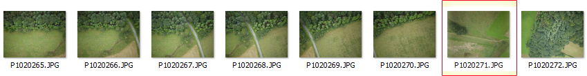
Imagery Sequences with Good Results:
Hope this information helps all you UAV mappers out there. Cheers,
JP Stoermer
http://dronemapper.com
Here is an example flight from a Pteryx UAV with 181 Images at 10 Mega Pixel. The flight elevation was around 275m average. The GSD (Ground Sample Distance) is around 13cm. We don't have support for GCP (Ground Control Points) yet, but that is on the way and will make results very accurate. We are still calculating the accuracy of our flights but they depend on a number of things because GCP are not used. This method can only be as accurate as the GPS unit. We estimate a 3-8m accuracy for georeferencing without GCP.
The above data is viewed in QGIS using Openlayers Plugin. It will read the .tfw, you should set the projection or your overall project projection to 33N WGS84 UTM.
Low Resolution 3D Point Cloud data is viewed in MeshLab.
You can download the results of this flight in high resolution for evaluation here.
I also setup an automated model generation from meshlabserver with a webgl viewer. It allows a nice preview of the 3D data. Tons of other updates and improvements thanks to feedback and testing from the beta crew! Thanks,
JP Stoermer
jDrones X1 basic frame, foldable
As one of our factories is manufacturing X525 type frames, we were able to make custom made frames for all our ArduCopter users. On this frame you can fit all earlier jDrones ArduCopter parts and extra accessories and we call it as jDrones X1.
Frame has thick aluminum arms that can take a lot of beating and same does those landing gears, they are all spring loaded to reduce forces from "bad landings".
Motormounts are made from stronger material than original X525 type frames usually are using. Frame also includes carrier boards and power distribution boards.
Frame details:
- weight is: 430gr
- fully foldable
- aluminum/fiberglass material
- power distribution
- battery strap
- style: quad
Best thing is it's price: 79.95
In it's folded form:
and more frames are coming soon.....
Hi guys!
In the last few months I have been working to develop an advanced tracking antenna for my new CGS. Unfortunately I haven't got no more time to finish this project, so I decided to release it Free to the community....
Basic Mechanics feature:
• 24dBi High gain dish antenna
• 9° Horizontal –vertical beam
• 360° Endless pan - 180° Tilt
• 0,006° Pan Resolution ( microstep mode)
• 0,05° Tilt Resolution (microstep mode)
• High torque speed stepper motors
• Precise bearings ad belts, for smoother operation.
• 2D construction (no need of 3 axis cnc)
• Cheap alloy-pvc-fiberglass
• Car roof mounting
• 7kg weight
Basic electronics feature:
• Integrated processor for standalone operation
• Single usb connection
• Integrated Serial usb converter for datalink
• Dual precise stepper drivers, low noise
• AHRS for stabilize the antenna
• 10Hz GPS
• Electronic tilt compensated Compass
• Internal lipo battery
The Electronics is almost done, just need to be checked again ( is the first PCB I develop).
In attachment a ZIP with all the files inside.
Unfortunately as you see on this post, my written English is very bad! I will try to give an help (as best I can) to answer to all the questions.
Regards,trackin antenna.rar