All Posts (14048)
Sort by
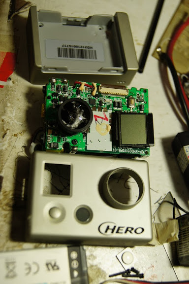
Go pro is very popular among the FPV pilot or UAVS builder, but not everyone like the fish eye extreme wide lense. Some people choose to buy an extra housing while other replace the standard lense with gopro flat lense. Based on our experince If you want a flat lense on Go Pro, no need to buy extra housing or a new lense... just crush your go Pro in to wall... !!!.
Few days a go our plane crash while testing auto pilot, the plane hit a stadium wall quite hard.. and unfortunately we put our GoPro on the front of the plane. The camera (without) housing hit the wall directly and the lens crack. This is what the lens look like after...
What suprise us.... the Gopro lense consist of few layer. It seems that each layer magnify the image and made it wider. In our case the lense is broken except the last layer... and after removing the broken layer we found that the last layer is a flat lense... and its working.
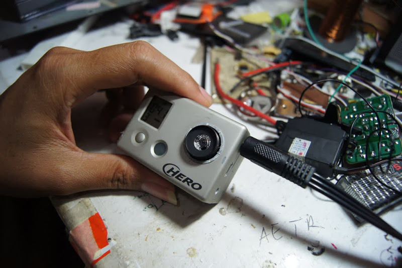
Here the image of the lens.... (the monitor is white and black), yes its flat... and more narrow angle..

Corius... we do some experiment, we replace the lens with used pocket camera lens.. and it works... !!

the image is good, but since the material is plastic its not sharp... i think if we use high quality glass lens the result will be great.... I'm curious if go pro also work with SLR lenses :D
Conclusion
* Dont throw away your old broken camera... the lens might be useful
* If you broke your gopro lens check again... does it broken to the bottom or just the first layer
* if you want flat and narrow image... no need to buy a new lens.. just hit your plane to the wall like we did :D
UPDATE
the modified lens work great underwater, just turn to get fix focus (the focus is diffrent betwen up and underwater) *thx to mas thoha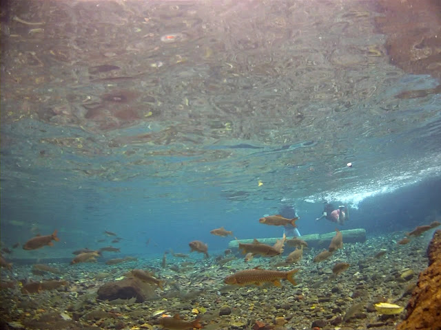
writer : oejang, amateur pilot
the tech guy : masthoha
the camera and lense are property of capung. www.capung.web.id
http://revision3.com/hak5/backtothestudio
what will be the best air-frame ( something from HobbyKing, what kind of wing ) to build this hybrid on ?
For the last week i have successfully flown my Twinstar with the APM. Everything was tuned and i had developed a good routine for setting things up in the field before flying. Yesterday the plan was to test a long endurance flight (25 min) that also used the relay to reset the XBee to keep the telemetry link for the entire flight.
But this is what happened...
The Twinstar comes with a small PCB that houses connectors for the motors and ESCs. The motor connectors are constructed in a way that they can't be connected the wrong way, but you can accidentally connect plus to minus and vice versa anyway which i found out... the connectors touched for just a split second, but that seemed to be enough to brick my APM. Mission Planner will not talk to it any more. The Arduino IDE doesn't like it either... I don't think the Mega 1280 is that sencitive, and i will investigate that further.
Fortunately i had a spare APM lying around... Some rewiring and a firmware upgrade and I was good to go. Almost...
I needed to recalibrate my radio for the new APM and ran in to all sorts of trouble. When i finally got everything in order i just wanted to do a last test of everything before flying.
It turns out that my ESCs needs a lower PWM than what my radio could give them (Without trimmint the throttle down... ) to keep the motors still. When i connected the ESC the motors spun up, one propeller hit the canopy and sent my xBee for a flight on it's own. Fortunately the xBee survied and i only need to replace one propeller.
Lessons to learned:
* Replace stock power connector on the Twinstar!
* Save your APM settings regularly. If you need to replace or reflash it you will need this file. Otherwise you need to start all over with the tuning process.
* Recalibrate radio after firmware uipgrade. Don't rely on the settings in your stored settings file.
Well i guess it's part of the hobby. New props are on their way and this gives me a reason to order a APM with the Mega 256 Kb chip.
Over and out.
Magnus
If you want to have a go at the MP32 from www.virtualrobotix.com, take advantage of the powerful 32bit ST ARM Cortex-M3 processor and would like to use your OILPAN with the great software the DIYDrones developres are developing, this is a small guide to get things started.
It will cover the biggest steps to configure the hardware and firmware.
Roberto has done a very good job, and since he lacks a bit in end user documentation (well that's tipical for almost every developer!!) I decided to give him a little help.
The code is ported form the 2.0.39 AC2 firmware and is is up-to-date with recent enhancemets. The planner will work just fine (at the time of writing 1.0.54)
The above is a video made by Roberto itself explaining setup for both the VRIMU and the OILPAN.
Below are details on the code to modify.
Have fun!
For more information please refer to www.virtualrobotix.com and http://code.google.com/p/multipilot32/ for the project home.
What you need to start
To start with the new Hardware set-up you need the follwing:
- Multipilot32 from www.virtualrobotix.com
- OILPAN rev H or older revision Foxtrap.

Before you can use the AC32 firmware you MUST solder two pin headers on the connectors shown below. You then need to short them in order to upload new firmware and fly! (you can use an old motherboard jumper plug to short the connector so you would be able to reuse your OILPAN on the old ATMEGA)

- USB to RS232 cable like this one Sparkfun USB to TTL or this: DROIDS USB to TTL
This is used to connect your MP32 to the Planner or to the CLI:

If you have an xbee working on your actual setup, you can use that instead of the USB-->serial, just hook it up to the Telemetry port as usual.
- Telemetry pins soldered on the OILPAN see:

- 4 cables female female to connect the usb adapter to the OILPAN on the Telemetry Port

- a Magnetometer(Optional) HMC5843 or HMC5833L soldered on top of the Oilpan

- a GPS(Optional) like this one: http://store.diydrones.com/MediaTek_MT3329_GPS_10Hz_Adapter_Basic_p/mt3329-02.htm
- a cable for the GPS module like this one (should have come vith your GPS module):http://store.diydrones.com/EM_406_uBlox_Adaptor_Cable_10_cm_p/ca-0001-06.htm

- You also need a bind plug to put the MP32 in firmware upload mode(see later...). Or you can use one female-female cable like the ones posted above.

First download and install software and drivers
Download the latest VRIDE Framework. At the moment it is the 0.0.4.5.7 link here VRIDE.0.0.4.5.7 unzip it and place it in a folder like C:\MP32
- You need to install drivers for your USB to serial adapter from here
- You need to install DFU drivers for your MP32 board. You can find the drivers in the C:\MP32\drivers\mapleDrv\dfu\ folder of the VRIDE just downloaded.
- Download the specifically modified firmware for the OILPAN from here OILPAN firmware. Unzip and overwrite the libraries folder in your C:\MP32 folder and the ACopter32 folder under the C:\MP32\Firmware\ folder
Installing the Mediatek GPS (DIYDrones)
At the time of writing only the Mediatek GPS from DIYDrones with firmware 1.6 is fully tested. The GPS needs to be attached directly on the MP32 board. To do this there are several ways. What I chose was to get a GPS cable adapter like the ones DIYDrones store sells and cut off one end that I solder directly on the board. You could also solder connector pins on both the MP32 and the GPS board and use a 4 wire cable.
This is a picture to explain what I did:

The 1st and last wire of the cable are not used, so you can cut them off. This is the schema on how to connect them:
| MP32 | Cable Wire # / Pin | GPS Adapter Circuit Board |
| JP19-2 (GND) | (2) | (GND) |
| JP19-4 (5V) | (5) | (5V) |
| JP19-6 (Ser4 Tx) | (4) | (IN) |
| JP19-8 (Ser4 Rx) | (3) | (OUT) |
This is where you will find the JPs on the board:

A picture shows were you can find the connectors:

Compiling and uploading the firmware
Configuring the VRIde
VRIDE is the "32bit version of Arduino". Is based on the LeafLabs? Maple IDE and uses a language much similar to the Arduino framework.
Once your hardware i ready and your drivers are finally set up you can start to open the vrobotix-ide.exe and in File-->Preferences choose the folder where you unzipped the VRIDE rar (eg. c:\MP32)

Then choose from the menu File-->sketchbook the Firmware-->Acopter32 sketch like in the Arduino framework.

This is your new firmware ready to be uploaded. But before we can continue we have to check and modify a few parameters in the code.
Modifying the code before the upload process
To let the compiler know you are using the OILPAN and not the VRIMU we need to make a few changes in the code. Nothing too difficult.Future developements will not require you to make all this modification, so keep up for the news! So follow these steps:
- Locate the libraries folder in your C:\MP32 folder and open with a text editor like Notepad++ the following files:
- AP_ADC\AP_ADC_ADS7844.cpp: be sure to comment out the #define VRIMU so the line would be //#define VRIMU like this:
//#define VRIMU- If you have the old compass HMC5843 you have to open the file AP_Compass\AP_Compass_HMC5843.cpp and add a new line at the end of the defines: #define HMC5843 otherwise if you have the most recent mag, leave as it is.
- Open the file AP_IMU\AP_IMU_Oilpan.cpp and comment out the //#define VRIMU and //#define VRMIMUIDG5000 line and add (if not present the line #define IMUOILPAN:
     #define A_LED_PIN   69  //37
     #define C_LED_PIN   71  //35

     //#define VRIMU
     //#define VRMIMUIDG5000
     #define IMUOILPAN
- Open the file AP_IMU\AP_IMU_Oilpan.h and do the same of before: comment out the //#define VRMIMUIDG5000 and add if not present the line #define IMUOILPAN:
     #include "IMU.h"

     //#define VRMIMUIDG5000
     //#define ADC_OBJECT
     #define IMUOILPAN
- Locate the folder Acopter32 in the Firmware subfolder (C:\MP32\Firmware...\ACopter32). Then open and modify the following files:
- In config.h:
- locate the //MAGNETOMETER section and modify the #define MAG_ORIENTATION as follow:
           //////////////////////////////////////////////////////////////////////////////
           //  MAGNETOMETER
           #ifndef MAGNETOMETER
           # define MAGNETOMETER                        DISABLED
           #endif
           #ifndef MAG_ORIENTATION
           # define MAG_ORIENTATION             AP_COMPASS_COMPONENTS_UP_PINS_BACK
           #endif
           #ifndef MAG_PROTOCOL
           # define MAG_PROTOCOL  MAG_PROTOCOL_5843  // Default Setting
#endif - locate the "Developer Items" section and modify as follow:
           //////////////////////////////////////////////////////////////////////////////
           // Developer Items
           #ifdef MP32
           //#define VRIMU
           # define IMUOILPAN
           //#define VRMIMUIDG5000
           #endif
- locate the //MAGNETOMETER section and modify the #define MAG_ORIENTATION as follow:
- In config.h:
Ok, so now the code is ready to be uploaded.
Uploading the code
- Now Plug the Bind Plug or one female-female jumper cable into the second input from the left of the MP32 (Called JP4_7, JP6_7 and corresponding to the 7th input of the old ATMega). Pins 1 and 3 must be connected toghether (The signal and ground pins)
This is used tu put your MP32 in firmware upload mode. When in this mode (and board powered) you will see a green led blinking on the MP32 board. This means you can start the upload process.
- Plug the USB cable directly into the MP32 USB port. This is used as a power source and as a communication port.
Like the Arduino IDE, before uploading the firmware check that the code compiles correctly by clicking the Verify button. If code compiles, you can click on the Upload to board button.
Wait for the completed upload message in the VRIDE message window.
Setting up the firmware for first use
Once the code has been uploaded you will be able to interact with it using the USB-->serial adapter shown above, you have to connect the adapter to the Telemetry port on the OILPAN. To get into the CLI you will not have to switch the slider. This mode is disabled!
You need to use a Hyper Terminal to get to connect to the CLI the first time. This can be found in Windows XP in START-->All Programs-->Accessories-->Communications-->Hyper Terminal. For Windows7 and Vista you need to download the Hyper Terminal program from here:http://www.megaupload.com/?d=J31857IQ. This is the original Windows XP program.
So now that you have the USB-->Serial connected to the telemetry port and Hyper Terminal connected to the COM, power up the MP32 using for example the usb port on it. As soon as you connect you will see a message saying to press S to enter interactive mode. You have five seconds to press S after boot up. This will let you in the CLI mode. Use the the SETUP-->Reset to reset the parameters, configure your radio, level, calibrate ESC as you will do in old ATMEGA chip.
The ERASE function is not necessary.
Using the Planner to finish configuration
Once you have done first configuration, you will be able to connect to the MP32 using the AC2 planner found here
For all the rest you can use the the Arducopter Wiki which will guide you through the rest of the setup.
Frames supported by the code:
- Quad X mode
- Quad + mode
- Hexa X mode
- Hexa + mode
Features actually not supported by the code:
- sonar is not implemented
- camera mount stabilization is not working
All the rest should be working! This is still BETA so use at your own risk, and please report any issues to the Issues list in the Multipilot32 google code project.
Cheers,
Emile
Hobbyking today released on their website na OSD System Combo which contains a main board, power module, USB/GPS/IR/TEMP Modules with a Remote.
 From their website:
The HobbyKing OSD Combo is a quick and easy way to add a wealth of on screen information to your FPV system. With GPS coordinates, airspeed, voltmeter, temperature, and many more display functions this OSD unit will make a great addition to any FPV setup at a fraction of the cost of other GPS OSD systems currently available. It even includes an IR sensor and remote control for wireless function control.
An excellent new feature of this system is the "home direction" indicator which works as follows:
"If more than 10KM/H or equivalent in MPH speed is measured by the GPS for not less
than half of a second, the system will switch the operating mode from “Landed” mode to
“Taken-Off” mode. The system will always compare between the current position
coordinate and the position measured in “Landed” mode, and calculate the “Home
Direction”, hence advises the pilot where the plane took off referencing to the current flying
heading. If you are lost during the flight, you may always fly back to the take-off
location by the referencing of home direction arrow."
OSD Display Features:
Timer
Date
Temperature
Power battery voltage
Power battery gauge
Power battery current
Power battery consumed energy
GPS status
Position Coordinate
Main Sea Level Altitude
Compass
Direction heading
Home direction
Relative altitude
Altitude scale
Climb rate
Maximum altitude reached
Distance to home
Speed scale
Speed reading
Auxiliary voltage status
Horizontal datum
Flight recorder status
Specifications:
Weight: Main board - 17g / Power module - 23g
Dimensions: Main board - 60x18x34 / Power module - 57x13x31
Edit: This seems to be the Apached OSD from AEORC. A manual can be found here
Price is US$ 56.94, but if you stay for about 30 seconds on that page, you will be offered to buy it for US$ 53.87 (can be different depending on your membership level)
The product page can be found here: http://www.hobbyking.com/hobbyking/store/uh_viewitem.asp?idproduct=17140
Useful tool or.....
No it'a not me! I just found it on RCG.
 "We finally flew our first thermal camera flight yesterday afternoon. About 10 seconds after launch my co pilot looked at the screen and said something like, "We now have our very own predator drone""
THANKS DIY DRONES COMMUNITY.
So this is my first actual build log on DIY Drones as I didn't want to be constantly updating the main page with little nitty gritty things. When things get quiet on a build log, you can assume people are busily working on their projects! I wanted to give a shout out to everyone that has made the APM purchase and setup a fairly easy process (with lots of reading, research and preparation).
I had started researching multicopters last December after I had sold a HK-600 after not liking the quality of it, and sick of trex-450 sized helicopters needing to be fixed constantly. Once I found the rcgroups discussion board and started my own build thread. See that for the specifics of what I have been doing for the past 8 months. We essentially started with an open source concept for a frame and camera gimbal but it never came to fruition. We drew everything up in Adobe Illustrator.
I knew I wanted to have functionality and immediately chose to go with the APM flight controller.
So over the past week I have managed to do all of my wiring up, mount the esc's, ensure they are calibrated correctly, mount the GPS, mount the APM, took off the 3.5mm bullets and put 4mm connectors on each motor lead, add deans to each motor wire to connect to the main harness and then removed them and wired it in directly, loaded the newest firmware and manage to reliably get three mores out of my dx6i without too much arsing around. I have it start in stabilize and can go into position hold or RTL. I can set it up do a mission of waypoints (AUTO) but it will not be often I will do that as it stands right now. Once I get the multicopter trimmed out I plan to attach a camera gimbal to it for aerial photo/video.
In terms of wiring, I wired two separate loops with seven wires coming from them each. I mounted them below the booms in the middle layer and above the booms in the middle layer. It fits in there quite nicely. From building it, I can already see that my next setup have the wiring going down the inside of the booms to make it cleaner looking.
I still need to balance the props but I wanted to spool it up for a brief proof of concept that it all works after 8 months of shagging around reading rc-groups, diy-drones and anything else that I could in relation to it. It was nice to see it working all at once. I have to equate the sound to about roughly the same as a trex 450, if not slightly louder.
I am hoping to tighten down a battery and do a maiden flight sometime in the next two evenings. I noticed that I was only going about a 1/4 throttle still when things started to get light. I quickly realized my roll and cyclic channels need to be reversed in the APM setup. I still have a problem with putting something on the hexacopter for orientation. I bought some ping pong balls but have no idea how to mount them yet without adding added turbulence and inherent vibration as a result. It is setup in 'X' mode for AP use. Any suggestions would be much welcome.I still also need to solder in a LIPO monitor or two and also install the telemetry modules I have ordered. A video FPV system needs to be selected and purchased which will be suitable for my needs and already purchased hardware.
The above is a very short test of my work so far.
As is customary and traditional, we celebrate every new 1,000 members here and share the traffic stats. We're now at 18,000 registered members. We had another month of more than a million page views. It just took us six weeks to get this latest 1,000 members, which is the fastest growth we've ever seen--we're averaging about one new member per hour. We expected the usual summer slowdown as usual, but there was no sign of it this year. Drones are hot!
Thanks as always to all the community members who make this growth possible, and especially the moderators who approve membership applications and blog posts and otherwise answer questions and keep things ticking here. We've got about 40 moderators now, but if anyone would like to join this group, please PM me. If you've been here for a while and have been participating, you'll fit in great!
This is a simulation I'm working on to improve the Altitude hold and change control laws. I have identical code from Arducopter running in Flash as OO Javascript so I can ensure the behavior is the same as the real thing. I sampled data from the barometer to introduce identical noise into each copter's solution. This allows me to test PID and other tricks side by side and see how the copter will behave. The copter itself is a simple physics equation and should be fairly accurate.
The Hover value is in your logs when you switch to Alt Hold. You should see it with the mode switch name. Mine was 495 which is the equivalent of 49.5% throttle. A lower value has a profound effect on the flight so play around with that.
The A copter is the current control solution. The B and C copters are Pi->Pi rate based solutions and are identical. You can adjust PID setting to pit the two against each other.
The scale on the left is meters. The Sonar is active and the mix is identical to the current AC2 solution.
This new code is in testing and will be available next week in 2.0.40b
Jason
This is a cool video and writeup I found on Adafruit.com:
"A micro camera is installed onboard an r/c plane F-16. The camera transmit live the video to ground and I wear video goggle to fly the plane in real time like if I was in the cockpit. The camera replace the head of the pilot and the movement of the cam is control by the movement of my head on ground via a head mount gyroscope (head tracker)
The whole system cost me around $1500 including the plane. But it is many hours of hand made modifcation. You can start with simpler video system that cost around $500 and install it on your own r/c plane. Search for FPV on the web for more info about my hobby…"

“With more than four years of customer funding behind it, our new Shrike VTOL unmanned aircraft system is designed to address the need for a small, light-weight hovering aircraft that delivers unique surveillance and intelligence capability not provided by current solutions. Not only does Shrike VTOL hover for more than 40 minutes with a high resolution video camera, but its innovative design also allows for the transmission of several hours of live video as a remotely emplaced perch and stare sensor,” said Tom Herring, senior vice president and general manager of AeroVironment’s UAS business segment. “This new solution adds an important set of new capabilities to our existing and battle-proven family of small unmanned aircraft systems that are saving lives in theater today.”
Full story
Another day, another cool feature to call out in the Mission Planner! (These posts are almost turning into a rolling tutorial series). In today's version (1.0.61), when you right click in the Flight Planner, you can directly enter commands such as Loiter and Jump along with the other commands shown above.
Jump is a handy command, which allows for proper mission scripting. It's like GoTo in Basic: it just jumps the mission to the start, so it can loop forever, or to any other waypoint.
A few small bugs also have been fixed, such as startup issues with older graphics cards.
This guy has a serious FPV ground station. Details here.
Buraq -1
This was developed in year 2000
1. Wing span is 12ft
2. Engine range is 100-250cc ( 100 is bit under power)
I suspect my first method for tuning PID loops was not a great hit because it required 3-view drawings or photos of the aircraft plus inertia data all of which is a bit fiddly. I've now got a new method based on flying the aircraft and logging accelerometer and gyro outputs in response to elevator, rudder and aileron doublets. This method works well with simulated data and I'd like to try it on real data. If you are interested in this experiment, let me know your email address and I'll send you more information and a short test specification.
As you've probably noticed, there are new features added to the Mission Planner almost every day (Michael Oborne is amazing). I thought I'd just highlight today's, which is neat. In the Flight Planner screen, your current Waypoint radius (the "hit zone" that qualifies as having arrived at the waypoint, which you can set) is shown. That makes planning missions much easier!
You can get the latest version of the Mission Planner by clicking the update button in the software or downloading it here.
Other recent updates include:
- level command ack update
- y6 pic
- HUD now runs opengl / bitmap fonts
- add apvar checking
- add format_version checking (eeprom map change)
- change all log file names to YYYY-MM-DD - to save confusion.
- fix small issue on multiple planners open
As always, you can track changes and update to all the code here.
After some painstaking PID tuning and some near crashes, I decided to take out my octocopter and see what kind of thrust it was able to generate. After hovering for a moment, I gunned the throttle and the machine disappeared into the sky. It was beautiful. The only problem was that I had forgotten my Xbee receiver and thus had no telemetry data. My glee quickly turned into panic as I tried to judge which way the octo was facing and how to get it back. As it drifted further and further with the wind, I collected myself and started to lower the throttle. It grew larger for a moment but I knew it was still drifting. I tested pitching backwards, to see if it would get closer, then pitched forwards.... forwards was the trick and it moved back within a comfortable range.
Moral: Never fly without telemetry OR a spotter. I had neither and my very expensive prototype almost disappeared forever because of it.
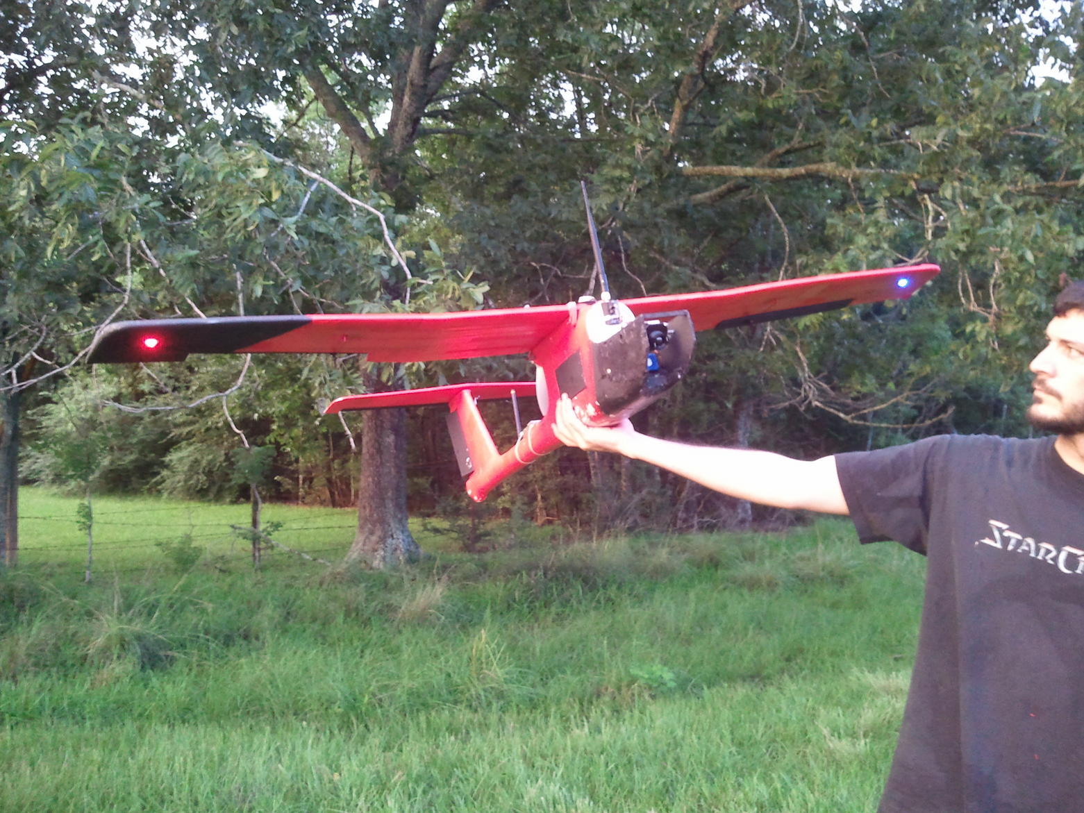
I've just equipped a falcon epo flying wing from hk with an ardupilot mega and a gopro.
I try to launch it with a diy bungee launcher without much success, this launch has not damaged the wing but after the second launch i've to glue it (after a crash because the wind have moved).
The motor is a dt750 with a 11x4.7 propeller. I need more rpm but i've nothing better to test it.
Photo of biggest UAV i did.