All Posts (14048)

Sort by

PIXHAWK Gumstix Camera makes it to product!

3689392036?profile=original

The design we pioneered in 2009 for machine vision with Gumstix Overo is now finally available as product from Gumstix. They did a great job of converting our initial raw open source design into a usable product, our internal prototype made it not beyond basic sensor readout routines. The picture on the top shows the finished Caspa board, the image on the bottom one of the earlier prototypes:

3689391986?profile=originalThe module provides 752x480 (640x480) pixel resolution in color and can be purchased from Gumstix either with IR (VS) or without IR cut filter (FS). For most applications not operating at dawn/dusk the version with IR cut filter will provide better image quality.


PLEASE NOTE: We're thrilled that this tiny machine vision platform is now available for the general public. PIXHAWK is however not associated to Gumstix or does benefit financially from the product. We're just happy that the concept of open hardware worked out again.


Read more…

Another ArduCopter build log. Part 2

Hello again.
A small update of my project (a part of it... ;))

Here we go, my A.A.P.D.B. - Alternative Arducopter Power Distribution Board

3689391697?profile=original


Simple double-sided board with extra kick.

It can handle 4 ESC's and a battery monitor. And the most important high current!!!


3689391768?profile=original3689391839?profile=original

Above is the board before etching.


As you can see the board is VERY simple but there are some cool features:

1. On the top side of the board there is a mesh connected to negative pole for ground providing and it acts as shield for PWM signals and for other electronics above the board like the APM, compass, x-bee, GPS etc...

2. Small 2 pin connector for direct battery connection, good for LED strips and battery monitors like this one from HobbyKing

3. All 4 PWM signals combined in ONE socket as well positive and negative wires from ONE ESC.

4. And 4 mount holes.


Some more pics from the making process:
3689391784?profile=originalEtching!!!

3689391862?profile=originalWashed...
3689391887?profile=original3689391959?profile=originalAnd cleaned....
The finished board:
3689392004?profile=original
3689391915?profile=original
Enjoy.
Schematic will be uploaded later this week. Next time: APM Heavy Duty Mount.
Read more…

3689391445?profile=original
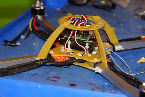
We are finally having manufactured a "shield" board for the Arduino platform that interfaces a Centeye image sensor with an Arduino to form a true (if simple) "smart sensor". This particular version is about a simple as you can make it:

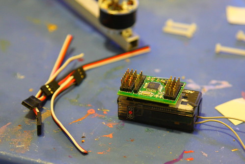
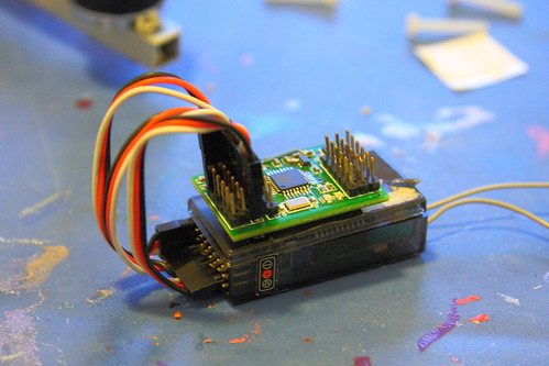
Shield Board: The board itself is a simple 2-layer board, and can be connected to either a full-size Arduino board (we've so far tried the Duemilanove and the Pro), or a mini-sized version (we've tried Sparkfun's Pro Mini). You need a 5V board to power the image sensor.

If one doesn't want to use the board with an Arduino, it is of course possible to just use it as a breakout board for the image sensor chip. The board design is open source.

Image Sensor: The shield board is compatible with any of Centeye's current image sensor chips, but for the above version we are using the Tam series- These are very simple image sensor chips requiring only five lines- Ground, Power, Clock, Reset, and AnalogOut. When you pulse Reset, a counter on the chip points to the first row, first column pixel, which is output as an analog value. Pulsing the Clock line advances the counter to the next pixel row-wise. That is it. The chips are available in two resolutions- Tam2 at 16x16 and Tam4 at 4x32, the latter with rectangular shaped pixels. I've also taken a leap of faith and decided to publish the schematic of the chip! We've released the analog portion down to the transistor level, and the digital portion down to the gate level.

Right now we have about 200-250 each of the Tam2 and Tam4 chips in stock, in bare die form.

Optics: The sensor will be shipped with a micro lens (about 1.6mm)- we can ship the board with the lens mounted or unmounted. In the latter case the Tam4 chip will be open and exposed, which is appropriate for people who want to use their own lens.

Sample code: I've also written a sample Arduino sketch that illustrates acquiring an image, obtaining a fixed pattern noise mask, and computing one dimensional optical flow from the 4x32 Tam4 chip. By cutting out the serial monitor and acquiring/computing optical flow on just one 32-element row, we obtained more than 200 frames per second- I think more is possible with further optimization. The source code is "open" and is intended to be a starting point for developing your own application.

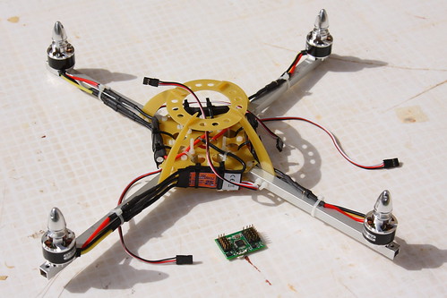
Uses: I didn't design this board for any specific application, but it should be able to do some things of interest to robotics. I've come to appreciate that it can be difficult if not impossible to make a "one size fits all" sensor, even if supporting just one mode (like optical flow). This is because there are many parameters that must be adjusted for each application. Thus for this board we are taking a different approach- rather than try to hide the optical flow computation from the user, we want the user to be fully aware of what is going on. In order to really use this sensor, you'll have to do some hacking of the code to tailor it to your application. I'll be honest- this is not for those who are afraid to hack a bit.  But I think the Arduino environment makes it very easy to hack, play around, and try different things. I'd appreciate your feedback on this approach.

As for what I think the board will ultimately support (with some hacking)- in the context of robotics and drones I think that things like wall following or basic terrain following should be doable (if on a forward moving platform). Several sensors should support some basic obstacle avoidance against large obstacles. Fulfilling the role of an downward optical flow sensor for a quad might be doable, but would require some careful optimization and algorithm tuning. I don't think impossible though- If the classic 1980's video game Defender could run, with rendering, on a 2MHz processor, then I would imagine adequate optical flow for a quad could be done with 16MHz. Please note though that I haven't tried any of these things yet with this board.

Just so that you know megapixels aren't needed- here are a few facts to consider:

1) Most flying insects have from several hundred to several thousand pixels. They have at most "kilopixels"! 2) We demonstrated altitude hold in 2001-2002 with 16 to 88 pixels, and obstacle avoidance in 2003 with 264 pixels total. 3) We also controlled the yaw angle of a helicopter with 8 (eight) pixels.

For the released files (including the Tam chip schematic), please visit this posting at Embedded Eye. For other details including purchasing, please visit this page at Centeye. Current asking price is $100 per board plus $9 shipping/handling for US customers. We hope we can lower this price in the future as we learn to automate working with bare die and the lenses in the current manner we use.

Please feel free to ask questions.

Read more…
3D Robotics

3689391624?profile=originalA couple startup companies are trying to create a new market for wind energy from "kites", which are really tethered UAVs flying circular patterns. Energy is generated by the props, which drive motors to act as turbines. The two are Makani Power, which is funded by Google, and Joby Energy, which also runs Joby Robotics, which we've been discussing in another thread for the closed-source Paparazzi IMU they just released.


The multiple-shot picture below shows Makani's UAV flying a typical pattern. A animation that shows it in action is here.

3689391720?profile=original

The Makani IMU-driven autopilot is described in detail here. Here a video showing it from the Ground Station perspective:


The Joby technology (shown at top) is similar, and appears to be a spin-off of Paparazzi's Booz IMU project. If you're familiar with the Booz quad-to-forward-flight aircraft, you'll recognize the videos on this page.


This month Popular Mechanics has a good article on both of them. It's not online yet, but here are the pages (click for full size):


3689391645?profile=original

3689391676?profile=original3689391747?profile=original3689391811?profile=original


Read more…

quadcopter attempt - phase 2


3689391604?profile=original


This is the sequel of my previous post, that I had to abandon more than 1 month ago, without actually being able to fly it... Ok, it's still not flying, but after:

  1. burning part of the Razor 9DOF IMU
  2. adding a Wii Motion Plus (for the gyros) to it
  3. replacing the .net micro framework board (Fez Domino) with an Arduino 
  4. replacing the Arduino with another Arduino based on AtMega 328 (as the code was too big)

I'm back in business ! :) And to prove it, here are 2 videos that show some proper balancing !


Actually, all this was only so that I can update the code, to feed  the gyros raw data directly into the PID controller algorithm (only for  the D part), as using solely the Euler angles from the DCM  transformation is too slow to react...
 
Again, it's not yet flying, but looks much more promising than 1 month ago... wish me luck ! :)
HERE you can find more details and the full history of this build...


dan

Read more…

QGroundControl 0.8.3 beta - User Configurable

This video shows how each user can configure the layout and even individual sliders and buttons of QGroundControl for his personal needs. This version is compatible with the current ArduPilotMega pre-release 2.0 codebase from the SVN repository (trunk). Please note that the video shows only a snapshot, not the final QGroundControl 0.8.3 release version (we're still improving it on a daily basis). User feedback is very welcome, if you want to try it yourself you can download a binary for Mac OS and Windows.


https://github.com/pixhawk/qgroundcontrol/downloads/

Read more…
Developer

Which Maxbotix sonar should be the standard?

3689391421?profile=original

    About two months ago we added altitude hold using the Maxbotix sonar to the ArduCopter (you can find instructions re how to set it up on the wiki).  At the moment on the we recommend the LV-EZ4 and XL-EZ4 but that's not based on a lot of research or experience so the question to the community is:

            Which one of the Maxbotix sonars is best for our purpose?  


     Above you can some pics extracted from the datasheets of the four sensors.  Each is a 1 foot grid and shows the theoretical range within which the sonar can sense a 3.5 inch pole (look at the black lines, not the red dots)


     The first choice is whether the extra cost of the XL over the LV is worth it - according to the data sheet the XL's range is 80% better (nearly twice the range) which makes me think "yes".
     The next choice (for either LV or XL lines) is between the EZ0 (fat-beam but longer range) or EZ4 (narrow-beam but shorter range).  We went with the EZ4 because we thought the narrow beam would make the altitude correction using roll/pitch work better but I guess we might be able to correct for the fat-beam of the EZ0 in the code and then we'd benefit from the longer range..but perhaps we would also get more false readings?
 
     So my guess is it should be the XL-EZ0 or LV-EZ0 but it would be great if people especially those who have played with sonars could voice their opinion/experience.  Also at least one person has had trouble with the XL-EZ4 over carpets and grass so if people have experience over various surfaces we'd love to hear about it!
Read more…
Developer

Python MAVLink interface (version 0.2)

mavlink-logo.png?w=400


For those of you who prefer a scripting language for your MAVLink needs, you may like to have a look at pymavlink, a Python implementation of the MAVLink protocol.I've just released version 0.2, which fixes some bugs, and adds support for the latest changes in the upstream mavlink git repository.

I initially wrote pymavlink to make it easier to develop MAVProxy, a little command line tool which provides a proxy between a MAVLink master and some number of slaves. I use this for a HIL setup between FlightGear, APM and qgroundcontrol. I'm releasing it more widely as I'm hoping it will be more generally useful to the diydrones community. It can be used to write little scripts that manipulate and display MAVLink messages in interesting ways.

The way pymavlink works is that you generate a custom mavlink python module using mavgen.py, which reads a set of MAVLink message definition files in their XML format, and spits out a ready to use python module that implements all the messages in the XML files.

A good example of what can be done with a short script is mavlogdump.py, which formats a qgroundcontrol MAVLink log file in a human readable manner. This really shows the advantage of using a scripting language for MAVLink, as it can easily display structures without having to write a lot of formatting code for each of the messaging types.

For our UAV project we are planning on using sets of python scripts with pymavlink to do things like mission planning, log analysis, camera control, image processing etc.

If you want to ask questions about pymavlink, it is probably best to join the mavlink mailing list.


Read more…
Developer


Here a video of a test flight of my Quad Rotor Observer (QRO) v8 with the FCWii board and the Wii Motion Plus (gyroscopes) + Nunchuk (accelerometers) MEMS sensors.


There was a strong wind during the tests flights (30 Km/h NW, gusting 40 Km/h, rainy...)
The tests flights have been successful, the model was very stable in spite of the bad weather conditions.
Normal flight mode and Auto-Level mode have been tested in the video.

Flight controller hardware:
- FCWii board v1.0 (ATmega 328P, Arduino PRO MINI 5V/16 Mhz compatible) from Fpv4ever
- Wii Motion Plus (genuine Nitendo version)
- Nunchuk (genuine Nitendo version)

Flight controller firmware:
- MultiWii V1_pre7 (compiled with the Arduino IDE) by Alexandre Dubus (Alexinparis)
firmware is uploaded via a FTDI 5V cable.

Quadcopter setup:
- 4 brushless motors DualSky XM2822CA 1450KV 7A
- 4 ESC 12A XC1210-BA
- Lipo battery 3S (11.1V) Turnigy Nanotech 2200 mAh
- receiver Corona CR6D 2.4 Ghz
- home made aluminum frame

The video has been taken with a GoPro HD Wide and a camera head strap.

Below the GUI for the setup and the tuning:

3689391489?profile=original3689391371?profile=original

3689391513?profile=originalMore infos at:
http://diydrones.com/profile/JeanLouisNaudin

Regards, Jean-Louis

Read more…
Moderator


We start to send the first batch of Multipilot32  to user and DevCoreTeam , i  hope that this video will be usefull in power on and uploading firmare . In the next day will be available more info about the first flyable code . The first software that i upgrade to MP32 is Arducopter NG. The first revision of code will be only a porting of mono task application to new micro controller . This is only first step of our work , a starting point this micro is more fast until 24x more flash 512 kbyte , more ram 64 kbyte ram. An a lot of advanced feature. And is cheaper :) 

I open a Call for C / C++ developer and beta tester  that would support the development of our project.

This is the repo of code : http://code.google.com/p/multipilot32/

In the next day will be available new code and doc in source branch inside redfox74. if you need more info contact me directly in PM or leave a message in the thread.

The board is compatible with all the DiyDrones accessories and is an upgrade of cpu from avr 8 bit processor to  32 Bit Arm Cortex . In this first stage we need advanced user that can develop code and have experiences on writing code on micro processor. 

 This is the official thread where there're some info about the project and roadmap.

http://www.virtualrobotix.com/forum/topics/vros-01-white-paper-simple


This is the main thread where you can found info for start to use Multipilot32


http://www.virtualrobotix.com/forum/topics/multipilot32-getting-started

3689389812?profile=original


IMG_1154


3689388740?profile=original


Read more…
Though quite brief the Canadian documentary " Remote Control War Zone" Showed clips of the Sparkfun autonomous vehicle competition and briefly interviewed Chris Anderson. The doc is very interesting to watch but I believed it to be exaggerated and put Amateur drones in a bad light as a evil technology that could be used by other countries for wars.

You can watch the doc online here: http://www.cbc.ca/documentaries/doczone/video.html
Read more…
Moderator

Turnigy Lipo's from HobbyCity.com

3689391285?profile=originalJust putting this out there...

I recently purchased 6 batts from HobbyCity.com and selected the USA Warehouse for shipping.  That was Wednesday the 23rd, it's Friday the 25th and they are on my desk.  I selected the USPS shipping option 2/3 day for less than $1.50 over the default shipping cost, bringing the cost of shipping to $11.  The package was sound and well protected.

I am very satisfied with the purchase.


I know that others have had bad times with some items from them, but if this is any kind of indication of turn around I'll be shopping HC more often and will purchase if the item is available from their US location.

Read more…
3D Robotics

3689391335?profile=originalSomehow I missed this when it came out in December, but NASA is running a competition for low-cost, energy-efficient autonomously-pilot passenger vehicles, which would take off and land from small "pocket airports" in neighborhoods. NASA is hoping for a winner of the autonomous challenge by 2015.

Gizmag has the whole story. Excerpt:

NASA’s Green Flight Challenge that is offering US$1.6 million in production funds to the winning design for a for low-cost, quiet, short take-off personal aircraft, that require little if any fossil fuel. The competition, to be decided next July, is being run by NASA’s light-aircraft partner CAFE (Comparative Aircraft Flight Efficiency), which envisions the resulting Suburban Air Vehicles (SAVs) taking off and landing at small neighborhood “pocket airports.”

Read more…
3D Robotics

3689391354?profile=originalI know this is a military drone, which we don't cover here, but I was taken by the screen shots of the ground control center of the X-47B, which had its first flight a few weeks ago. HappyKillmore--yours looks way better!

The video has also been re-released with a new rock soundtrack, which is actually pretty good. Check it out:


Read more…

Pipo quad progress

5476038416_7f7fc91804.jpg

5476855929_168f4e3af7.jpg5476856709_279d6ed4f7.jpg5476857673_1f6fb74220.jpg


Here's the latest on Pipo board development. Code already contains AHRS, PID, PWM and multiplexer routines.   I still need to complete the AP/GPS routines, the simple configurations via the radio and only after that I'll tackle the AP routines.


As it is I think I'm doing OK for space.  I'm currently using ~40% of program space and ~15% of eeprom space so there should be enough room left over for the AP.

Read more…
3D Robotics

3689391142?profile=originalThe Paparazzi team have released a new IMU board called Asprin. It's just the accelerometers, gyros and magnetometer sensors (no processor) and is available for $110 at Joby Robotics.

Strangely, I can't find any mention of it being open source. Is it actually possible that Paparazzi is no longer supporting open source hardware? That would be sad if true. They seem to have deleted the Hardware folder from their repository. [Correction: the hardware repository is here. It only has the schematic of Lisa (no board file) and no files at all for Asprin]. I've asked for clarification, but haven't heard back yet.

Remember that Paparazzi's tagline is "Bringing freedom to UAV since 2003". Maybe it should be "Bringing freedom to UAVs, 2003-2010" ;-)


[UPDATE: The official statement: "For the time being the Eagle files for Aspirin are not released in a OSHW definition compatible way. We at Joby Robotics would love to be able to release the files. But we don’t feel comfortable with that at the moment. It is a continuing discussion here at Joby Robotics, so let’s hope for the best! :)

P.S. Aspirin is not a “Paparazzi” design as such, it was developed at Joby Robotics with close collaboration with Paparazzi community. It may have not been reflected by the article properly for some readers."]


[UPDATE2: On March 3rd, the Joby team did decide to release the files and open source the boards. Lisa is here and Asprin is here. Good news!]


]


Read more…