All Posts (11086)

Sort by

When Microsoft announced the Surface Dial last October, I immediately knew, that no better application could be developed for this controller than controlling the flight path of drones. For weeks I checked availability in Europe, only to order an overpriced device from the US Ebay finally. As it arrived I probably got one of the first Surface Dials in Europe...

This device literally cries to be integrated in my virtual cockpit software FlightZoomer. It is a perfect fit as an efficient, yet simplistic man-machine interface, to control the FlightZoomer autopilot (FlightZoomer is a Boeing 787 alike UI + system layer on-top ArduPilot).

But it was worth the effort: Changing modes by pressing and selecting target values by turning - how more simple could flying be? One man - one hand - one controller!

In the video above, you can see how the controller perfectly supports relaxed flying as well as street canyon hunting...

Read more…

Update

3689715047?profile=original

The design is almost complete so thought I would share it.

The remaining part is the connection between booms and the chassis, which needs to be strong and provide vibration resistance. 

All I've come up with so far is a 'rubber grommet sandwich' with M4 bolts/washers etc, seems simple but somehow inadequate.

The PixFalcon will have its own foam/gel damper but extra isolation seems worth the effort.

Ideas & inspiration welcome :-)

Read more…

3689715085?profile=original

We have reached the seventh week in our autopilot precision series. In this series we test different drones and autopilots by flying them on a simple photogrammetry route created in UgCS.


So far we have tested quite a few drones, including DJI Phantom 4 and 3, DJI Naza-M V2, Mikrokopter Quad XL, DJI A2 as well as PX4. This week we put the DJI Inspire 1 to the test for both – stop and turn and adaptive bank turn trajectories.

The results are in the video below:

Download the KML files


Get the newest version of UgCS here:
https://www.ugcs.com/en/page/download

Safe flights,
UgCS Team

Read more…

3689715056?profile=original

Commercial drone applications
 require significant autonomy and intelligence which cannot be achieved using conventional Computer Vision algorithms. Deep Learning/Vision algorithms seem to be very promising in helping drones to be used in more advanced and complex commercial applications.

Getting a deep learning application working perfectly on a desktop is nontrivial, and when that application has to run on a single board computer aka Companion Computer controlling a drone, the task becomes quite challenging.

FlytOS provides a framework to alleviate these challenges by helping in an easy integration of your deep learning application with drones. It provides you the right set of Drone APIs and Drone SDK to build advanced drone applications.

We will post a series of tutorials to get a simple Deep Learning application like this video

… up and working on a Nvidia TX1 board running FlytOS.
In this tutorial, we will integrate Caffe, a popular deep learning framework widely used for Deep Vision.

For the demo, we will use a famous object detection and localizing network known as the Single Shot Multibox detector or SSD in short (https://github.com/weiliu89/caffe/tree/ssd).

A little knowledge about ROS will be helpful in understanding the tutorial better.

Making a catkin_ws:

We will have to make a catkin workspace for the ROS package we are going to write. If you already have a catkin workspace set up on your TX1, skip this step. In our case our workspace name is flytos_tx1. Clone the following repository: https://github.com/flytbase/flytos_tx1 as a reference to this tutorial.

Making Caffe:

Change your directory to ~/flytos_tx1/src/ssd_caffe/ and clone the caffe repository here by typing following commands:

git clone https://github.com/weiliu89/caffe.git
cd caffe
git checkout ssd_caffe

Now we have to make and install Caffe. You can refer the following link http://www.jetsonhacks.com/2016/09/18/caffe-deep-learning-framework-64-bit-nvidia-jetson-tx1/ as it is a nice resource on building Caffe for the TX1. Or follow these instructions:

Install some dependencies by typing the following commands:

sudo apt-get install cmake libprotobuf-dev libleveldb-dev libsnappy-dev libhdf5-serial-dev protobuf-compiler libatlas-base-dev libgflags-dev libgoogle-glog-dev liblmdb-dev python-dev python-numpy

sudo apt-get install –no-install-recommends libboost-all-dev

Then copy the example Makefile.config.example into a file name Makefile.config

cp Makefile.config.example Makefile.config

If you want to enable the use of CuDNN libraries for accelerated performance, uncomment the line USE_CUDNN in Makefile.config. Then enter the following command:

cmake -DCUDA_USE_STATIC_CUDA_RUNTIME=OFF

Next, add the following line at the end of Makefile.config to solve some issues related to making Caffe on Ubuntu 16.04:

INCLUDE_DIRS += /usr/include/hdf5/serial/

You can finally make caffe by typing these 2 commands:

make -j4 all

make install

Compiling nodes in our ROS package:

If you look at the CMake file our package ssd_caffe (~/flytos_tx1/src/ssd_caffe/CMakeLists.txt), you can see the 2 lines help Catkin in finding the required Caffe libraries to be linked to your ROS nodes.

set(CAFFE_INCLUDEDIR caffe/include /usr/local/cuda/include)
set(CAFFE_LINK_LIBRARY caffe/lib /usr/local/cuda/lib64)

Change your directory back to the catkin workspace and enter the following command to compile your code:

cd ~/flytos_tx1
catkin_make

Right now there is just an empty file in the source directory.

In the next tutorial, you will learn how to make your first ROS node with imported Caffe libraries. Stay tuned!

3689715104?profile=original


Thanks to Zubin and Pradeep for preparing this demo.

For any queries, you can reach out to us on Forums or FlytOS Developers Group.

Source

Read more…
3D Robotics

Free webinars on drone design simulation

3689714945?profile=original

Two years ago Simscale had a good series of free webinars on using simulation tools for drone design. Now they're doing another series on May 11, 18 and 25.  From the announcement:

The growing community of private DIY Drone designers and manufacturers has inspired us to create a workshop series focusing on the simulation of a drone design. The series is directed to makers and drone enthusiasts, who want to learn how to modify and optimize their own drone design.

Participants will receive a hands-on, interactive introduction to the application of engineering simulation in DIY Drone Design, and will learn from top experts how to leverage the free, cloud-based SimScale platform for their own projects and designs.

Every webinar session comes with an optional simulation homework assignment and submitting all will qualify you for certification and prizes. There is no prior knowledge or software required to join this webinar series. All participants will get free access to SimScale with all the required simulation features.


Overview:

  • The Drone Design Workshop will consist of a series of 3 one-hour webinar sessions
  • The live, online sessions will take place on Thursdays at 5:00 p.m. Central European Time, with the first session starting on May 11th
  • Learn how to virtually test and optimize drone designs
  • Get dedicated and individual support to learn how to perform fluid dynamics, structural, or thermodynamics simulations.

Session 1 – 11th of May, 2017

AERODYNAMICS & PROPELLER DESIGN


In the first session, the trainer  will talk about to the fundamentals of aerodynamics and propeller design. You will learn how to predict the performance of your design using fluid flow simulations. Following this, you will design your own propeller as part of the homework.


Session 2 – 18th of May, 2017

STRUCTURAL SIMULATION


The second session of the drone workshop introduces participants to structural simulations of assemblies which can be very challenging. Beside this, we will also discuss strategies for lightweight design and how to apply them to your own models.


Session 3 – 25th of May, 2017

DROP ANALYSIS


The third and last session is dedicated to the simulation of a drop crash. Simulating the impact of the drone for several velocities will help you 
understand the critical falling velocity of your design.


Interested? Register for free and attend the SimScale Drone Design Workshop.


Read more…

3689714837?profile=original

We appreciate all the feedback and feature requests over the last couple of months! Thank you

You can now process up to 150 images from DJI sensors for free on your Windows 10 desktop. We've also added NDVI calculations and a load of other new features to the software. Download the latest version at the following link: DroneMapper Software & Downloads | Drone Mapper Imagery Processing and visit this link for changes/updates: https://dronemapper.freshdesk.co ... onemapper-changelog

Download example data here: https://dronemapper.com/sample_data


April 13th, 2017 - v0.7 b20170413-735

  • Added functionality to export .txt file(s) containing Omega, Phi, Kappa, X, Y, Z orientation (relative and world positions)
  • Overnight mode, run all processing steps automatically
  • Various UI tweaks and bug fixes
  • Increased free DJI processing limit to a maximum of 150 images

February 12th, 2017 - v0.7 b20170212-712

  • Add NDVI generation option, creates ENDVI and NDVI from NIR orthomosaic (REMOTE, EXPERT only)
  • Add image EXIF pre-processor, metadata generator
  • Additional, improved blending for orthomosaic (REMOTE, EXPERT only)
  • Improved UI feedback from backend API, display dm3d current task count/status
  • Improved logging
  • Processing speed improvements
  • Fixed bug with DEM scaling and certain AGL EXIF tagged data collections
  • Add DSM/hillshade generation option, creates gray scale DSM render from DEM (EXPERT only)
  • Add support for FLIR Vue Pro thermal cameras (JPGs)
  • Preserve ortho preview / geo-reference results, no need to re-run once completed


DroneMapper REMOTE/REMOTE EXPERT generated NDVI:

BoetMBtb3cjiwYCpOVKUCAuGf8Gv1aEN1Q?1488817536&width=600

3689714903?profile=original

Thx @pix4d for sharing the original imagery for these two data sets on their website.

Read more…

A new look on survey and mapping with Reach RS

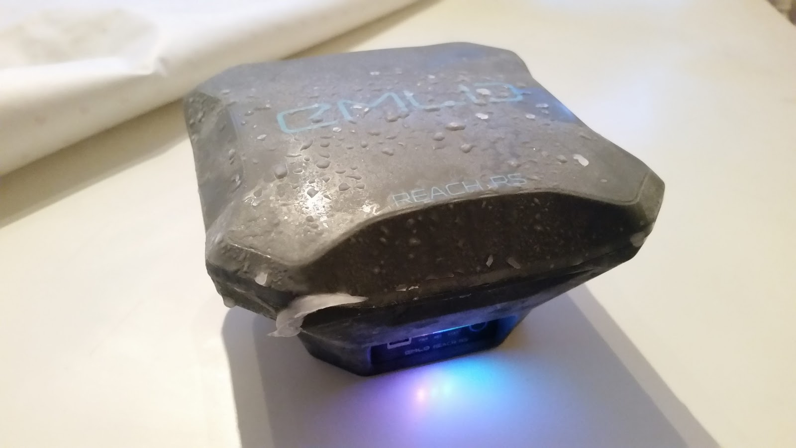
3689715009?profile=original

Hey everyone,

In our latest blog post we’ve introduced the new version of ReachView app for both - tiny Reach RTK and freshly launched Reach RS field-ready receiver.

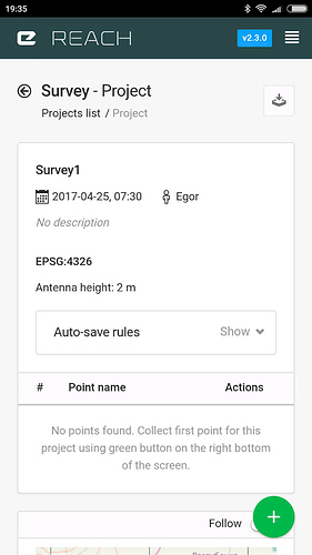
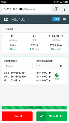
What makes this release so special is a handy point collection feature. Besides providing the main configuration funtion, ReachView v2.3 appears as a self-sufficient survey tool running on your RTK unit!


rHklVLKGMTT0d70-YY1vXW_RvPV0po5IckufJsc78bNvel5awz-8FRYKJIruJk6ALu2txzJvfH35SzZBS_mh8XrbrKCUAjxvMp-TWeNy6YVohb-xI6DU0rNgd_39T4B8fSQRdA-o?width=250ZSlI3nVx4FBVcI1A8R5MMwwva7LKj65O1G_6vOGFcfRydH9Bgf2220S-SfeQYngyHy2ZUeZwxw6aDSoRckP6s-hyVp_kQZ2qIEoBcZppuMAOgptLuwIU7kC38WND4_2wSP1W6ST9?width=250

Screenshots of Survey Tool

Reach and Reach RS have been waiting for this feature. After few hours from the official announcement:

3689715024?profile=original

New Survey feature in ReachView provides:

  • Project-based point collection

  • Collection screen with a real-time progress indicator, RTK and averaging statuses

  • Collect the points either manually or with project-wide autosave rules

  • Project view with a map and summary point list

  • Export your data to DXF, GeoJSON, Esri shapefiles

All this is making ReachView a great assistant in the field. A set of Reach RS and a smartphone or tablet is all you need to conduct survey or collect Ground Control Points (i.e. before mapping with Drone Deploy)!

As you see it is a big release for us and we will push the functionality even further.

Emlid Community is actively sharing feedback about the first tests with Survey Tool and here is the demo of workflow prepared by Emlid pro-user @TB_RTK.

We’re also getting great reports about how Reach RS is doing from all over the world. We’ve picked some of them and want to share first @Luke_Wijnberg extensive field-tests in South Africa - find it in our blog.

TlUZekS2WOTpFg6o-WtnfWnsWHkw3myOFqc3gyUtbraRLLncti_IChFtPhHORBsGbUvXx4lec-IYlUA5_26Q_Vlia49ZFVC8Wtnpv5WLUYPLJ9rytafNLkuXN4nEN8G5RkD5B5gB?width=350vE_3E02UD2orwnitI49RvZfxUfK1p9mB-racIiS5TqNscq5H2Wh73ZN9eEsoo7FyYXRbP-9VCW2_HSudmExYjPu42MwYS0dnaQYw7giLDebYZrzGm2t3yYFZU5Q3YfsESnqcHr2T?width=200

Reach RS in South Africa


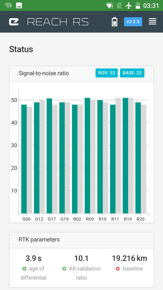
Reach RS has built-in LoRa radio as one of many connectivity options providing a reliable correction link up to 8 km. We thought so. Actually with the LoRa modulation it is possible to hit up to 19km in line of sight and the story cutting all doubts of it came from Canada. You’ll find detailed tests of Reach RS built-in radio in this article.

1GvT8BL9WlyAVZxOVfT7DzeJ2nG3Cqi-xr1Yx5VwxFmyobUKHiWOLuxJnB01xkHg6AWDAfEwd4gAG-FwfYeXF0JR2W1KD5aHQDFvxilu4f6nb4TIXSxAFo55Ht2mOU99Vd6nXnHj8-7K6-mDUcwqQ6YQJ8wR7cady95ZLc9S0CgrsX5bXlirqskpkxIOiv-4Wpq1v2XDALtvoA41md9dsBFgAqHJrvu2Iwm9TFit2-vBURd7f3hL1zTtUmYRbpi_pRmftlG3kP4GJ4tP

Reach RS in Canada


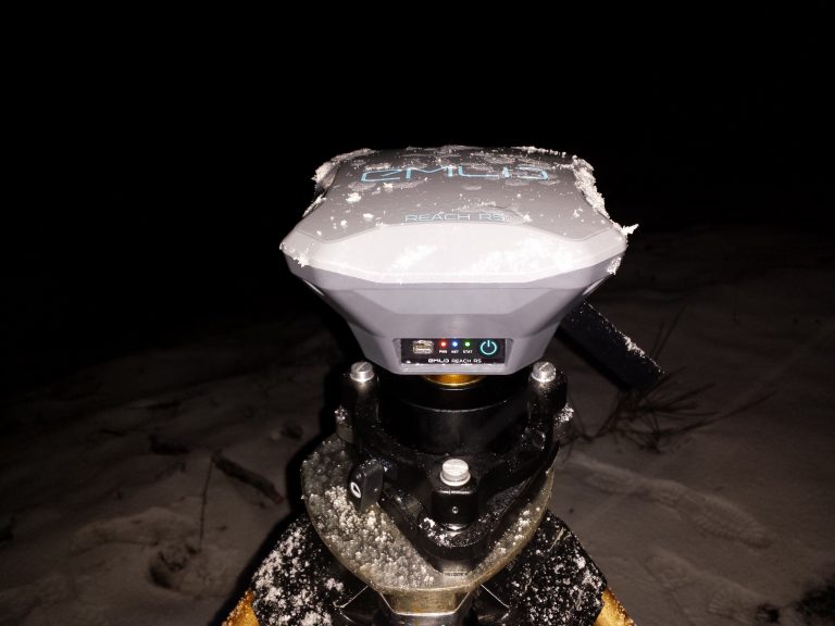
Reach RS is rugged and durable, we told this on the product page and in press release, but to make sure:

RC buggy crash test

91-uKiiEwIi_Mw4ja1Qvoaigl0398xtMiclfxFfiZdsCBOA1QjBLZ9AzwG9NSo11hnOZaESVm7yqR1i7YtLa5gpVzy9gyNmK65zTJ-iqDBAqLDxLh7ASjdRH5dzKtg5gLVaIf96u?width=374

The unit photo after 24 hours in -26C


The full compilation of different cool things (including AutoCad360 + Reach demo) is available here.

New Reach RS docs (btw we've got new docs!) featuring some tutorials you might be interested: 

  • Using QGIS as Survey tool with Reach RS (link)

  • Mock the location with Reach on your Android device (link)

  • Quickstart tutorial of setting up two Reach RS devices as a base and a rover with correction link over Lo-Ra radio is now ready (link)

RS is already used in the variety of projects including survey, mapping, precision agriculture, bathymetry!

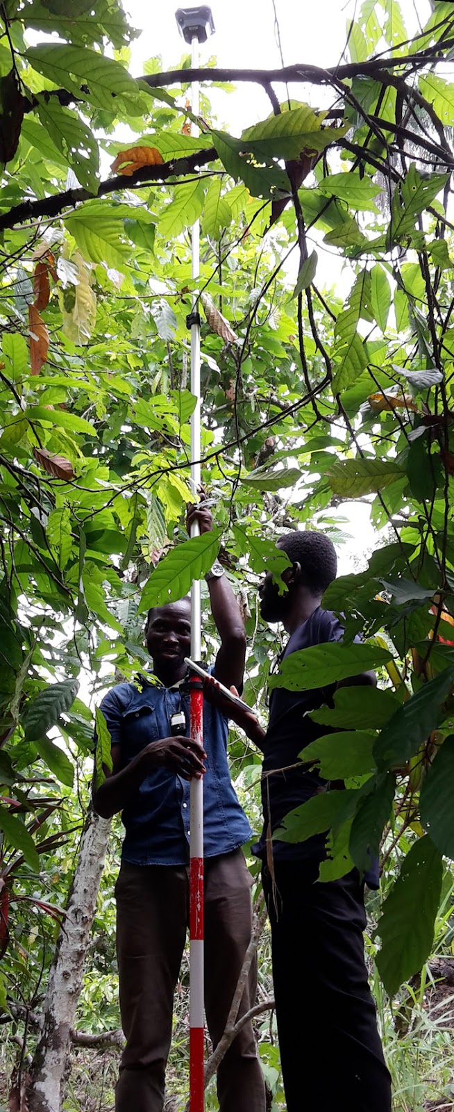
wJy6rE1kL3wkQUOs6wnqx3PQ_FQ5VrpHg5adCKG-JDkaOBA8rrGI-bJko0ce76J8X3Jp64hEq6vdwLl0DT6ezZhFoD_xlLSiLBC-tmHmYKGdJJ1s83DXVsO4IjJCZRvmZZQO6giu?width=186

Survey in Ghana by LandMapp


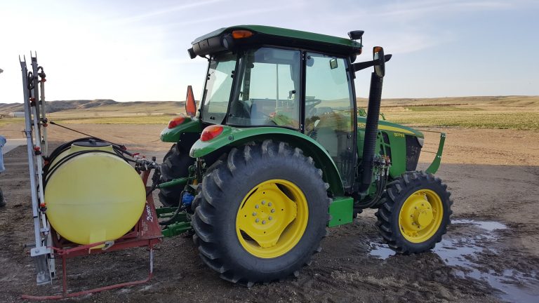
FmeZqDVD1yT72Cw3NycCmKZsOLQOGcGkNIPtuDNEc3Ifu40al234RrYYsaujm7SCuiXqOjktl0awiWMPAInV2yHC9ZyhX2iG9wJoqHd768JEWRzpfJBxAcfnAQPiUtiZa1jiPIbL?width=453Reach RS for tractor gps guidance in the US (check it out)


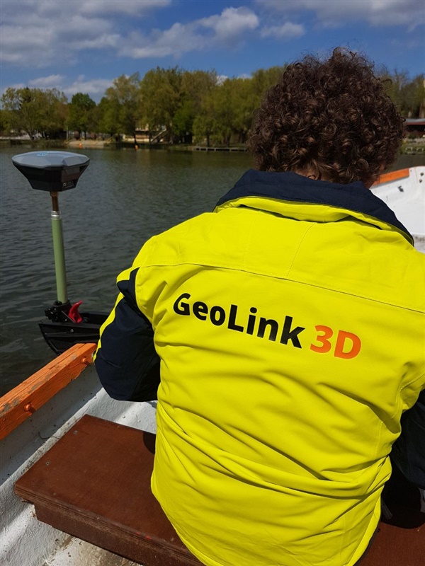
43BpMWi8HmD5t-wV-CIWZhOeYHCu9bHh_1nDZcjCq68AXC80NucdPJfdNIr9BPXYRpG8neBJjX648KxH_rgLpZqFrKD-MaHg5m55ZmIWxkMpbeQaZNb4o9x_eUP8BSA36PUe3v_L?width=241

Bathymetry by GeoLink 3D in Hungary


Join our community forum, build drones, share projects and subscribe to newsletter, a lot of more interesting stuff is coming soon!

Thank you for reading!

Read more…

3689714958?profile=original

We launched the brand new GNSS RTK Board, the Precis-BX306 to market in April. A series of other new products and accessories were also showcased. Click here.

The launch of Precis-BX306 aims at facilitating the applications which need centimeter positioning accuracy and dynamic operation mode, enforcing effective observation data logging and management, and popularizing the adoption of high precision in aerial mapping and drone-related integration.

Compared with previous Precis GNSS RTK boards, Precis-BX306 further improves the reliability and continuity of positioning performance in challenging environments as it supports GPS L1/L2, GLONASS G1/G2, Beidou B1/B2 with 192 tracking channels. It can easily integrate into Pixhawk and other autopilots. The event mark and PPS features provide more possibilities for shutter synchronization.

Product address:

https://www.tersus-gnss.com/products/precis-bx306

More details:

https://www.tersus-gnss.com/

Read more…

Frame design.

3689714922?profile=original

I've been experimenting with frame design, an essential component to keep all the parts flying in formation.

I printed some interlocking plastic parts in 2mm PLA & super glued them together to see how rigid/strong the end result.

The attached pic shows about half the fuselage section, it weighs 23 grams and seems more than strong enough. 

So far so good.

Read more…

Live-Streaming-1.jpg

From: http://dalybulge.blogspot.co.uk/2017/04/low-latency-wireless-video-on-all-your.html

Today I discovered that I am able to have super low-latency Wireless video on all my drone devices and i'm super-happy with that. What this means is:

I can have video on my laptop with Ardupilot's Mission Planner:

I can have video on my Nvidia Jetson:

Also, video on Android using Tower app:

I am particularly happy that I can capture fast wireless video on the Jetson board. I think this enables a host of opportunities to integrate with AI experiments from  the ground ensuring your code runs before mounting. I like it. I like my mini 210mm size Ardupilot drone too. Such a good tiny thing to experiment with without fear of breaking it.

I like that I can use both Tower and Mission Planner to provide both video and telemetry, my range tests have been around 1km. I can effectively launch, view and control using my tiny smartphone alone. Cool.

I can even capture on both smartphone, laptop, and jetson at the same time equally so I can launch and monitor using smartphone or laptop, and have the jetson AI experiments running seperately so as not to affect flight control should my Jetson code crash. Good stuff! Now I'm fairly sure, that DJI won't let you do all that.... Thanks to open source community.

2222.jpg

YouTube Live - Streaming.

So what now? one thought I had was to learn about live streaming my live flight footage. There are many options and many platforms to do this - Livestream.com, Ustream.tv, and lots of others listed here, and many more i'm sure, as well as social media platforms which are now allowing live streaming. There are literally gazillions of services out there.

Sticking with just one service for my experiments, making a snap choice, I went with YouTube live to see if I could stream on my many devices. Here's how it worked out.

Android Smartphone

I used Youtube Gaming app on my android device to stream my live drone footage. It is probably the smoothest path to successfully streaming on all my tested devices. Setting up is easy, streaming works, and the compactness of a smartphone means you're not lugging around heavy equipment with wires trailing behind you n the dirt. I suspect this is the way forward for most people.

Laptop

I chose to look at OBSproject.com as my first choice software for this test, mostly because it is free and has no nag-screen or watermarks. I have tried other software in the past such as wirecast and Vidbaster, I found Wirecast to be the least resource heavy software, that is, the one which made my laptop get less-hot than other software. Vidblaster is feature rich but resource heavy.

OBS was a new one to me so I tried it out. It works fine and setup is easy for youtube live streaming on my laptop. I approve of it. Maybe I will retest wirecast and vidblaster for live streaming my live drone footage in future to compare. There are other software listed here to try too.

Jetson TK1

Pushing the envelope a little bit, I decided to try live streaming to youtube live using my Nvidia Jetson TK1 board which uses Ubuntu 14.0.x and is 32-bit. It wasn't successful. Primarily, this was because the go-to Linux streaming & encoding software ffmpeg.org does not appear to be already installed on the Jetson, and when I tried to compile it, I was flooded with errors, so I gave up on it after a day. Fail. There is also a version of OBSproject for Linux which I wanted to install, but alas, it is dependent upon ffmpeg being installed firstly.

Raspberry Pi 2

I decided to give my Raspberry Pi 2 a go, instead of one of my Pi Zero W boards. Mostly because the pi 2 is more powerful than the pi zero W. I was more successful with my installs than with the Jetson board - I compiled and installed easily, learned the appropriate scripts, set them up as .sh scripts to run, and got the live footage to successfully stream/cast/encode to Youtube servers.

However, on my laptop, waiting for the stream to show up, I got the initial green dot of success, the good message 'Stream Starting' and this looked good....I waited. It didn't show up. I considered it a fail.... But such a close success.

Reasons for failure? I don't know. I tried many different encoding and script variations for ffmpeg, but it seemed to fail either at the Youtube server end, or, (guessing) my router blocking it. Why this is, I do not know. It seems to want to work, it gets youtube live to initialise the stream, but I never get the video appearing. I spent so may hours on getting Raspberry Pi & ffmpeg running it caused my brain to melt.

So that is where I am now at. I recommend Laptop or Smartphone for streaming your live flight footage, but the Jetson and RPi is a bit of a struggle. Perhaps the Jetson TX2 will work better than the TK1, assuming the TX2 is using 64-bit, Ubuntu 16.04 which I am assuming will work better with ffmpeg than 14.0.4 LTS on the TK1. Discovery is key.

I think the Raspberry Pi board is very close to to being a successful streaming board. I might keep at it. Some questions I have to solve.

Thanks for reading.

Read more…

Robotized Radiation Mapping

Dear community members,

This is very preliminary work on aerial robotic radiation detection in real-time and in a GPS-denied manner. The robot localizes based on visual-inertial data and integrates a deferentially installed 2-radiation detectors solution to exploit their polarity characteristics. Most of the research is ahead but we feel the topic is exciting and would like to communicate it to all of you. In this link you can get updates of our relevant work: http://www.autonomousrobotslab.com/robotics-for-nuclear-sites.html ;

As shown, it is not only referring to the radiation detection itself but also to the relevant challenges involved such as the autonomous navigation in visually-degraded environments:

Best,

Kostas

Read more…
3D Robotics

More powerful Pixhawk 3 coming soon

3689714598?profile=original

The PX4/Dronecode team and Drotek have been working on the next generation of Pixhawk autopilots, and you can now see a preview of that with the Pixhawk 3 Pro. It's based on the new PX4 FMU4 Pro standard, which includes a full suite of next-generation sensors and and the more powerful STM32F469 processor. It's designed for the Dronecode/PX4 flight software, which is the current official Pixhawk standard.

The board is currently in developer release, but will be taken out of beta after testing is complete in the next month or two.

All details are here (and below):

------------------

Introduction

FMUv4-PRO takes input from all of the Pixhawk stakeholders; end users, developers, researchers and manufacturing partners. Goals for this iteration of the platform are:

  • – An integrated, single-board flight controller for space constrained applications
  • – A modular multi-board flight controller for professional applications
  • – Sufficient I/O for most applications without expansion.
  • – Improved ease-of-use.
  • – Improved sensor performance
  • – Improved microcontroller resources (384 KB RAM, 2 MB flash).
  • – Increased reliability and reduced integration complexity.
  • – Reduced BoM and manufacturing costs.


Key design points

  • – All-in-one design with integrated FMU and optional IO and lots of I/O ports.
  • – Improved manufacturability, designed for simpler mounting and case design.
  • – Separate power supplies for FMU and IO (see power architecture section).
  • – Onboard battery backup for FMU and IO SRAM / RTC.
  • – Integration with two standard power bricks.


Technology upgrades

  • – Microcontroller upgrade to STM32F469; flash increases from 1MiB to 2MiB, RAM increases from 256KiB to 384KiB, more peripheral ports.
  • – ICM-20608, MPU9K integrated gyro / accelerometer / magnetometers.
  • – LIS3MDL compass (HMC5983 is now obsolete).
  • – Sensors connected via two SPI buses (one high rate and one low-noise bus)
  • – Two I2C buses
  • – Two CAN buses
  • – Voltage / battery readings from two power modules
  • – FrSky Inverter
  • – JST GH user-friendly connectors


I/O ports

  • – 6-14 PWM servo outputs (8 from IO, 6 from FMU).
  • – R/C inputs for CPPM, Spektrum / DSM and S.Bus.
  • – Analog / PWM RSSI input.
  • – S.Bus servo output.
  • – 6 general purpose serial ports, 2 with full flow control, 1 with separate 1A current limit, 1 with FrSky protocol inverter.
  • – Two I2C ports.
  • – Two external SPI ports (unbuffered, for short cables only).
  • – Two CANBus interfaces.
  • – Analog inputs for voltage / current of two batteries
  • – On-ground usage piezo buzzer driver.
  • – Sensor upgrade connector scheme
  • – High-power RGB LED.
  • – Safety switch / LED.


Mechanical Form Factor

  • – 71 x 49 x 23 mm (with case)
  • – 45g (with case)
  • – Standardized microUSB connector location
  • – Standardized RGB led location
  • – Standardized connector locations


System architecture

FMUv4-PRO continues the PX4FMU+PX4IO architecture from the previous generation, incorporating the two functional blocks in a single physical module.


PWM Outputs

Eight PWM outputs are connected to IO and can be controlled by IO directly via R/C input and onboard mixing even if FMU is not active (failsafe / manual mode). Multiple update rates can be supported on these outputs in three groups; one group of four and two groups of two. PWM signal rates up to 400Hz can be supported.

Six PWM outputs are connected to FMU and feature reduced update latency. These outputs cannot be controlled by IO in failsafe conditions. Multiple update rates can be supported on these outputs in two groups; one group of four and one group of two. PWM signal rates up to 400Hz can be supported.

All PWM outputs are ESD-protected, and they are designed to survive accidental mis-connection of servos without being damaged. The servo drivers are specified to drive a 50pF servo input load over 2m of 26AWG servo cable. PWM outputs can also be configured as individual GPIOs. Note that these are not high-power outputs – the PWM drivers are designed for driving servos and similar logic inputs only, not relays or LEDs.


Peripheral Ports

FMUv4-PRO recommends separate connectors for each of the peripheral ports (with a few exceptions). This avoids the issues many users reported connecting to the 15-pin multi-IO port on the original PX4FMU-PRO and allows single-purpose peripheral cables to be manufactured.

Five serial ports are provided. TELEM 1, 2 and 3 feature full flow control. TELEM4 can be switched into inverted mode by hardware and has no flow control. Serial ports are 3.3V CMOS logic level, 5V tolerant, buffered and ESDprotected.

The SPI ports are not buffered; they should only be used with short cable runs. Signals are 3.3V CMOS logic level, but 5V tolerant.

Two power modules (voltage and current for each module) can be sampled by the main processor.

The RSSI input supports either PWM or analog RSSI. CPPM, S.Bus and DSM/ Spektrum share now a single port and are auto-detected in software.

The CAN ports are standard CANBus; termination for one end of the bus is fixed onboard. .


Sensors

The new ICM-20608 has been positioned by Invensense as higher-end successor of the MPU-6000 series. The software also supports the MPU-9250, which allows a very cost-effective 9D solution.

Data-ready signals from all sensors (except the MS5611, which does not have one) are routed to separate interrupt and timer capture pins on FMU. This will permit precise time-stamping of sensor data.

The two external SPI buses and six associated chip select lines allow to add additional sensors and SPI-interfaced payload as needed.

IMU is isolated from vibrations. 

Power Architecture

Key features of the FMUv4-PRO power architecture:

  • – Single, independent 5V supply for the flight controller and peripherals.
  • – Integration with two standard power bricks, including current and voltage sensing.
  • – Low power consumption and heat dissipation.
  • – Power distribution and monitoring for peripheral devices.
  • – Protection against common wiring faults; under/over-voltage protection, overcurrent protection, thermal protection.
  • – Brown-out resilience and detection.
  • – Backup power for IO in the case of FMU power supply failure.
  • – Split digital and analog power domains for FMU and sensors.


FMU and IO Power Supplies

Both FMU and IO operate at 3.3V, and each has its own private dual-channel regulator. In order to address issues seen with PX4v1 and noisy power supply connections, each regulator features a power-on reset output tied to the regulator’s internal power-up and drop-out sequencing.

The second channel of each dual regulator is switchable under software control. For FMU this is used to permit power-cycling the sensors (in case of sensor lockup), and for IO this will make it possible to perform the Spektrum binding sequence.


Power Sources

Power may be supplied to FMUv4-PRO via USB (no peripherals in this mode) or via the power brick ports. Each power source is protected against reverse-polarity connections and back-powering from other sources. Power spikes observed on the servo bus (up to 10V) led to the removal of the power-from-servo option, users wanting this feature can connect the servo rail with a cable containing a Zener diode to the 2nd power brick port.

The FMU + IO power budget is 250mA, including all LEDs and the Piezo buzzer. Peripheral power is limited to 2A total.


Power Brick Port

The brick port is the preferred power source for FMUv4-PRO, and brick power will be always be selected if it is available.


Servo Power

FMUv4-PRO supports both standard (5V) and high-voltage (up to 10V) servo power with some restrictions. IO will accept power from the servo connector up to 10V. This allows IO to fail-over to servo power in all cases if the main power supply is lost or interrupted. FMUv4-PRO and peripherals combined may draw up to 2A total.

Power is never supplied by FMUv4 to servos.


USB Power

Power from USB is supported for software update, testing and development purposes. USB power is supplied to the peripheral ports for testing purposes, however total current consumption must typically be limited to 500mA, including peripherals, to avoid overloading the host USB port.


Multiple Power Sources

When more than one power source is connected, power will be drawn from the highest-priority source with a valid input voltage.

In most cases, FMU should be powered via the power brick or a compatible offboard regulator via the brick port or servo power rail.

In desktop testing scenarios, taking power from USB avoids the need for a BEC or similar servo power source (though servos themselves will still need external power).


Summary

For each of the components listed, the input voltage ranges over which the device can be powered from each input is shown.

Brick ports Servo rail USB port
    FMU 4 – 5.7V no yes
    IO 4 – 5.7V 4 – 10V yes
    Peripherals 4 -5.7V, 2A max 4 – 5.7V, 250mA max yes, 500 mA max


Peripheral Power :

FMUv4-PRO provides power routing, over/under voltage detection and protection, filtering, switching, current-limiting and transient suppression for peripherals.

Power outputs to peripherals feature ESD and EMI filtering, and the power supply protection scheme ensures that no more than 5.5V is presented to peripheral devices. Power is disconnected from the peripherals when the available supply voltage falls below 4V, or rises above approximately 5.7V.

Peripheral power is split into two groups:

  • – TELEM 1 has a private 1A current limit, intended for powering a telemetry radio. This output is separately EMI filtered and draws directly from the USB / Brick inputs. Due to the noise induced by radios powering a radio from this port is not advised.
  • – All other peripherals share a 1A current limit and a single power switch. 

Each group is individually switched under software control.

The Spektrum / DSM R/C interface draws power from the same sources as IO, rather than from either of the groups above. This port is switched under software control so that Spektrum / DSM binding can be implemented. Spektrum receivers generally draw ~25mA, and this is factored into the IO power budget. S.Bus and CPPM receivers are supported on this rail as well.


Battery Backup :

Both the FMU and IO microcontrollers feature battery-backed realtime clocks and SRAM. The onboard backup battery has capacity sufficient for the intended use of the clock and SRAM, which is to provide storage to permit orderly recovery from unintended power loss or other causes of in-air restarts. The battery is recharged from the FMU 3.3V rail. 


Voltage, Current and Fault Sensing :

The battery voltage and current reported by the power brick can be measured by FMU. In addition, the 5V unregulated supply rail can be measured (to detect brown-out conditions). IO can measure the servo power rail voltage.

Over-current conditions on the peripheral power ports can be detected by the FMU. Hardware lock-out prevents damage due to persistent short-circuits on these ports. The lock-out can be reset by FMU software.

The under/over voltage supervisor for FMU provides an output that is used to hold FMU in reset during brown-out events.


EMI Filtering and Transient Protection :

EMI filtering is provided at key points in the system using high-insertion-loss passthrough filters. These filters are paired with TVS diodes at the peripheral connectors to suppress power transients.

Reverse polarity protection is provided at each of the power inputs.

USB signals are filtered and terminated with a combined termination/TVS array.

Most digital peripheral signals (all PWM outputs, serial ports, I2C port) are driven using feature series blocking resistors to reduce the risk of damage due to transients or accidental mis-connections.

Inputs / Outputs

InputOutput pixhawk pro by Drotek

Read more…

FlytBase Now Also Supports Ardupilot

3689714782?profile=original

FlytBase now supports Ardupilot.

Ardupilot Companion Computers users can now install FlytOS on Intel Edison, NVIDIA Jetson TX1, Intel Aero, Qualcomm Snapdragon Flight, Raspberry Pi 3, ODROID XU4 etc. and get access to extensive Drone APIs and Drone SDK to build custom drone applications.

Visit https://flytbase.com to get started.

Extensive Drone API documentation is available for multiple programming languages and technologies like ROS, C++, Python, Rest and Websocket.
For Ardupilot users using Pixhawk or Pixhawk2, FlytBase adds a lot of other capabilities, like, integration with ROS, OpenCV for building intelligent applications. It also provides you RESTful, WebSocket endpoints, and comes with ready SDKs for building custom web/mobile apps. Basically, it helps you leverage the true potential of your companion computer on Pixhawk or Pixhawk 2.

For those, who already have an activated FlytOS running in their devices, need only to connect to the internet. FlytOS would auto update itself.

Compatibility for Intel Joule and NVIDIA TX2 is on its way.

You can follow the easy step by step guide to Get Started with FlytOS and Companion Computer. Install FlytOS on your CC and try out available Sample Drone Apps.   
See the Developers section to start building your own drone apps.  

For discussions, you can join us on our Forums or FlytOS Developers Group.

Look forward to working with other members on building interesting drone applications!

Read more…
3D Robotics

3689714866?profile=original

From DARPA. Have you ever seen so many swarming Iris+s?

Service Academies Swarm Challenge Live-Fly Competition Begins

U.S. Army, U.S. Navy, and U.S. Air Force academy teams compete in education-focused experiment to pave the way for future offensive and defensive swarm tactics for warfighters

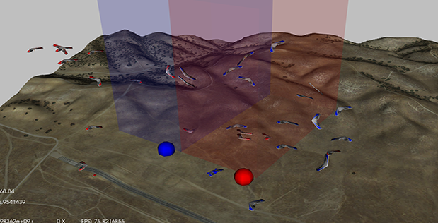
Image Caption: This data visualization portrays the swarms of unmanned aerial vehicles that flew today over Camp Roberts, Calif., while implementing autonomous swarm tactics designed by Cadets at the U.S. Military Academy and the U.S. Air Force Academy for the DARPA Service Academies Swarm Challenge. U.S. Army, U.S. Navy, and U.S. Air Force academy teams are competing in an education-focused experiment designed to pave the way for future offensive and defensive swarm tactics for warfighters. Click below for high-resolution image.

Small unmanned aerial vehicles (UAVs) and other robots have become increasingly affordable, capable, and available to both the U.S. military and adversaries alike. Enabling UAVs and similar assets to perform useful tasks under human supervision—that is, carrying out swarm tactics in concert with human teammates—holds tremendous promise to extend the advantages U.S. warfighters have in field operations. A persistent challenge in achieving this capability, however, has been scalability: enabling one operator to oversee multiple robotic platforms and have them perform highly autonomous behaviors without direct teleoperation.

To help make effective swarm tactics a reality, DARPA created the Service Academies Swarm Challenge, a collaboration between the Agency and the three U.S. military Service academies—the U.S. Military Academy, the U.S. Naval Academy, and the U.S. Air Force Academy. An experiment at its heart, the research effort is designed to encourage students to develop innovative offensive and defensive tactics for swarms of small UAVs. Today the effort started its three-day Live-Fly Competition at Camp Roberts, a California Army National Guard post north of Paso Robles, Calif., which is hosting more than 40 Cadets and Midshipmen to demonstrate the highly autonomous swarm tactics they have developed since work started in September.

“In less than eight months, you have shown yourselves to be dedicated and talented participants in a complex and timely research effort,” Timothy Chung, the DARPA program manager leading the Swarm Challenge, told the teams. “DARPA is proud to have you—our future warfighters and Service leaders—participating in this endeavor to explore offensive and defensive swarm tactics. Now is your chance to show each other, DARPA, and our invited Defense Department guests your precedent-setting work toward an important goal: helping future U.S. forces maintain superiority in tomorrow’s technological and mission environments.”

“Not to mention your chance to claim bragging rights over your rival academies,” he added.

Teams

The Service Academies Swarm Challenge is the most recent example of how DARPA works to ensure the technological superiority of U.S. military forces by periodically engaging the U.S. military Service academies in research-oriented competitions. These competitions aim to cultivate the great potential of young officers-to-be and encourage their career-long collaboration with DARPA. In both 2014 and 2015, for example, DARPA conducted the DARPA Service Academy Innovation Challenge and the Service Academies Cyber Stakes.

A fourth-year capstone design course, the Swarm Challenge has pushed students to achieve “zero to swarm in eight months.” The goal: help the academies go from having little swarm-related expertise to developing capabilities with potentially near-term applicability for operational training and fielding—all within one academic year.

“This is one of the first opportunities for the next generation of operators and tacticians to explore and understand swarm-versus-swarm interactions,” Chung said. “It's not just about the platforms or the links or the communications—it’s about behaviors. That's one of the key takeaways for the Service Academies Swarm Challenge: that we're really zeroing in on swarm tactics as a battle skill. That's where advances will reap innovative benefits for future warfighters.”

Ranging in size from 11 to 21 students, the teams bring cross-disciplinary expertise in diverse technical and nontechnical fields, from computer science, robotics, and systems engineering to military strategy and operations. The students also bring fresh insights that DARPA and the U.S. military can learn from—and potentially expand upon—to enhance the tactical effectiveness of swarm systems.

DARPA provided all the hardware, much of the software, and a lot of know-how to get the teams started. The Agency also developed new support infrastructure to enable the teams to practice and compete in a virtual environment in preparation for this week. DARPA initially provided some example swarm tactics and the teams have since designed a number of their own to debut at the Live-Fly Competition.

Gameplay

The Service Academies Swarm Challenge is testing cutting-edge swarm tactics through a time-honored game that is all about tactics: Capture the Flag. Two teams at a time play inside the Battle Cube, a cubic airspace 500 meters on a side, 78 meters above the ground. Each team has been given 20 fixed-wing UAVs and 20 quad-rotor UAVs and, under the rules of play, can field a mixed fleet of up to 25 UAVs for each of two 30-minute battle rounds. Each team protects its “flag” (a large, inflatable ground target) while trying to score the most points before time runs out.

Teams seek to score the most points in the following ways:

  • Air-to-air “tags” by using a simulated (virtual) weapon to hit a sensor on an opponent’s UAV in flight
  • Air-to-ground “tags” by physically landing a UAV on the opponent’s “flag” located on the ground
  • Accomplishments in swarm logistics by launching as many UAVs as quickly as possible and keeping them aloft as long as possible

As scheduled over the next three days, the first match pits Air Force against Army; the second, Army plays Navy, and the third match has Navy squaring off against Air Force. The team that wins both of its matches wins the competition and takes home a trophy and bragging rights.

Technical Challenges

While people often think about swarms as simply being large collections of robots, swarms in fact have five defining characteristics: number, agent complexity, collective complexity, heterogeneity, and human-swarm interaction. The Service Academies Swarm Challenge is designed to explore these characteristics as they apply to both offensive and defensive swarm tactics, and to harness and leverage them for warfighter benefit.

Operationalizing swarm-related capabilities poses many significant challenges, from technology (e.g., battery size and life, user interfaces) to logistics (e.g., transport, upkeep) to understanding the limitations of what swarms can do. The Swarm Challenge provides an experimental testbed that manages these challenges so the academy students can focus on creating innovative swarm tactics.

DARPA’s interest in developing breakthrough swarm capabilities for national security extends beyond the Swarm Challenge to a number of current programs exploring autonomy, communications, and other technologies, including:

Looking Ahead

The results of the Live-Fly Competition remain to be seen but the Service Academies Swarm Challenge has already planted the seeds for future growth in the increasingly important domain of swarm tactics. Thanks to the past eight months of work, all three academies now have basic curricula and frameworks for conducting unique, accelerated research and field experiments on swarm tactics. The institutions also have dozens of students who have worked side-by-side with leading-edge researchers and operators experienced with advancing the state of knowledge of swarm systems.

“The Cadets and Midshipmen participating in the Service Academies Swarm Challenge will soon be officers, where they can further hone their swarm-tactics skills and share their know-how with fellow Service members,” Chung said. “Building on the lessons they have learned, they can help accelerate us toward a near future in which Service members are able to quickly take advantage of anticipated advances in unmanned aerial system technologies and apply their skills in new and ever more creative ways. No matter which academy comes out on top here, U.S. warfighters will be the ultimate winners.”

Read more…

Cheap Fixed Wing Mapping

3689714400?profile=original

"Ten thousand dollars?!?! It's just a piece of foam!"

If you've uttered those words, this post is for you.

We will not debate the value of quality or workflow simplicity contained in that $10,000. What we will do is demonstrate how to make a "cheap" consumer fixed-wing drone generate high resolution orthomosaics with a simple, repeatable workflow.

Tiny violins from here on out.

giphy.gif

If you are starting with nothing, it will cost a little over $1800 to assemble all of the required hardware.

The finished hardware setup.

3689714438?profile=original

Required Components:

Parrot Disco: $1,199

Hero5 Black: $390

Taranis w/ Rx: $237

Once you get the Disco and power it up for the first time, remember that it is just a WiFi access point running Linux. You can telnet and ftp to it like a normal network device.


3689714478?profile=original

When you're connected via WiFi, the Disco will be at 192.168.42.1


3689714506?profile=original

The goal here is to replace the brains of CHUCK with APM:Plane firmware. The primary advantage is increased flexibility in autonomous flight control and planning.

Let's take a look at the directory structure inside CHUCK.

3689714500?profile=originalI used this guide to get this plane up and running with APM:plane.

In short, there are only three things you need to do to make Disco run the APM flight code. (double check your file permissions when you write these files!):

1) Upload the latest stable arduplane kernel to the /data/ftp/internal_000/APM directory. I used FTP to upload the file.

2) Create the start_ardupilot.sh script. I used vi to create mine in the same APM directory.

3) Modify the existing /etc/init.d/rcS_mode_default boot script to support the APM kernel. 

3689714345?profile=original

Your Disco is now ready for persistent boots into the APM:plane firmware. Let's finish setting up the hardware.

Connect the Taranis receiver and GoPro. The receiver plugs in via the servo connector wire (see above image), and you'll need to dig out some foam to fit the Hero5. There is nothing to damage in this section of the plane so be careful, but don't worry about hitting anything.

3689714525?profile=original

Some extra foam was removed on this installation to accommodate other sensors.

We chose the Hero5 Black for three reasons:

1) Self contained power system

2) Internal geo-referencing of images

3) Internal intervalometer

When considering other sensors, remember that losing any one of those features can significantly increase the complexity of the installation.

Once connected via Wifi, open a UDP connection in Mission Planner to verify correct operation of the vehicle.

3689714616?profile=original

The mavlink connection will open, and you will get live updates in mission planner.

3689714541?profile=original

Next you should compare your parameters with this known good parameter file.

3689714630?profile=original

Once you write those parameters to the vehicle, you are ready to check all of your surface responses. Here's how I normally do it:

1) In manual mode, check for normal control surface response in pitch and roll.

2) Switch to Fly-By-Wire A and check for proper surface corrections to roll and pitch attitude of the vehicle.

3) Still in Fly-By-Wire A mode, check for proper control surface output to transmitter input.

If you are not seeing proper control surface response, I would start by looking at the ELEVON_OUTPUT parameter. I use setting number 2. (Here's a great video from Mark Harrison if you need elevon help! https://www.youtube.com/watch?v=yvlCbs1NeC4)

When your control surfaces check out, you're ready to go for a maiden flight.

My typical maiden:
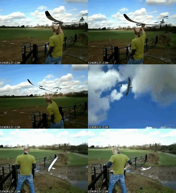
giphy.gif

Everyone handles maiden flights differently, but here are a few tips for this Disco configuration with APM:

1) I use 3 modes; Manual, Fly-By-Wire A (FBWA) and Return-To-Launch (RTL).

2) Launch in FBWA mode at 3/4 throttle. Any of the normal wing launching methods will work.

3) Get "three mistakes high" and try manual mode. You will need to trim the vehicle

4) Once those two modes are working, try RTL.

With a successful RTL, you're ready for an AUTO mission.

Create your polygon in Mission Planner, right click inside the polygon and go to AutoWP -> Survey Grid.

3689714668?profile=original

I used the Hero4 camera model, and increased the sidelap to 80% to generate my pattern.

3689714563?profile=original

The AUTO takeoff and landing works very well with this configuration. Do not be afraid to try it. Landing only requires two additional waypoints. LAND at 0 altitude where you want the plane to stop, and one waypoint before it about 200m away at 30m altitude.

3689714648?profile=original

Upload your mission to the vehicle, and then download it back to your ground-station to confirm accuracy.

When you're ready for your first AUTO flight, here are a few things to keep in mind:

1) Don't forget to turn on the camera! I used a 2 second timelapse, and it was way too many pictures. 700 images that were culled to 150 to produce the final orthomosaic. The GoPro WiFi was on and did not seem to affect my range checks. The voice activation is actually useful, "GoPro start a timelapse" was all it took to get going.

2) If you want telemetry throughout the flight, you'll need a WiFi adapter with an external antenna. Your laptop wifi antenna will not stay connected throughout the flight.

3) I keep the same three modes on the transmitter and put the vehicle into AUTO from the groundstation.

4) Once armed and in AUTO, you shake the vehicle to activate the motor and AUTO launch. Throw it into the wind and it will be on its way.

5) The vehicle is extremely well tuned. This mission was flown in 10-12mph winds on the ground.

6) It takes practice to nail AUTO landings.  Be ready to take over control on long or short landings.

3689714400?profile=original

Ok, you've got your vehicle back after your successful mapping run. What next?

Remember that this is not a "smart" distance based capture. You need to go through your images, and cull the ones where the vehicle is turning, or has a lot of water in it, etc....

Then send it to your favorite orthomosaic tool!

For this example, I used Pix4D Desktop. I used 100% default settings on the 3D Maps profile. Full processing took about 2 hours, and it came out great for this sensor!

3689714697?profile=originalAnd a closer in view of the ortho.

3689714723?profile=original 

From here, there's a lot of room to explore. Larger capacity batteries, higher quality RGB imaging sensors, multispectral imaging sensors, atmospheric sensors, extended telemetry range or leveraging the on-board OEM RGB sensor would all be great extensions to this platform.

We will see how long the airframe holds up; but Disco is a consumer product with readily available and inexpensive spare parts. You will not break the bank with, "Two is one and one is none."

In summary, you don't need $10,000 to create large area, high spatial resolution maps with a fixed wing drone. A relatively small amount of money and basic maker skills can get you a cutting edge mapping platform from three boxes of consumer products.

Please let me know if anyone else tries this! Good luck!

Read more…

3689714584?profile=original

Several lessons were identified here  from the entry of The Groundhog hexacopter in the MAAXX Europe competition earlier this year.

Current developments are around correcting the issues so that we get a UAV successfully lapping the oval track at a minimum average speed of 1m/s.

A number of changes in approach have been made from that previously blogged.  Recall the platform is based on a combination of Pixhawk/Raspberry Pi3/OpenCV/Dronekit.

Image analysis:

  1. The birds eye view image transformation in OpenCV was causing segmentation faults on the RPi.  Instead the position and bearing of the detected line is calculated using straight trigonometry.
  2. Improvements made to the ranging ROI bands to further speed-up the frame rate.  This is now at a reported 50fps (which is faster than the PiCam is supplying them).

Control algorithms:

  1. The use of quaternions has been temporarily suspended in favour of control by velocity vectors.

As in MAAXX Europe, it makes sense to initially test on a straight line.  Initial testing was conducted outdoors using red-seatbelt webbing for the line.  It was not possible to fly below about 2m as the propwash blew the line away (will sort that next time!).

Initial Testing (Links to YouTube Video).

https://youtu.be/YBgSgMYjt8s

Read more…

Looking for challenge

3689714852?profile=originalHi,

after finishing my last project, I'm ready for the next challenge.
However,  right now I can't afford to start another project and buy components for development, although I'd have ideas of course.

So I'd like to offer my experiences in 3D modelling, printing and basic programming skills for some interresting development!!!

What I'm looking for is:

  • participate in 3D development of airframes, planes, gimbals or similar
  • optimizing parts and components for 3D printing (strength, printability, weight optimization)
  • doing FEM strength analysis on parts or multiple parts
  • building and testing complete multirotor or fixed-wing (and of course helicopters, see one of my blog posts earlier) systems

Please note that because of software rights, I can only provide native 3D file formats as a result (step, iges, stl, dwg, dxf, etc.).

I'm located in Hungary, Europe, my email address is nhadrian@gmail.com. 

Regards
Adrian

Read more…
3D Robotics

OpenMV is my favorite computer vision camera, and it combines a built-in OpenCV-like machine vision library with a microPython interface, all in one little board for $65. It also speaks MAVLink, so Patrick Poirier was able to do the above with just these extra lines of code to the standard built-in color tracking example:

while(True):
clock.tick()
img = sensor.snapshot()
for blob in img.find_blobs([thresholds[threshold_index]], pixels_threshold=100, area_threshold=20, merge=True):
img.draw_rectangle(blob.rect())
img.draw_cross(blob.cx(), blob.cy())
send_landing_target_packet(blob, img.width(), img.height())
print("TRACK %f %f " % (blob.cx(), blob.cy()))

and then send the result to Pixhawk via MAVLink:


def send_landing_target_packet(blob, w, h):
global packet_sequence
temp = struct.pack("<qfffffbb",
0,
(((blob.cx() / w) - 0.5) * h_fov)/2.25,
(((blob.cy() / h) - 0.5) * v_fov)/1.65,
0, #int(z_to_mm(tag.z_translation(), tag_size) / -10),
0.0,
0.0,
0,
MAV_LANDING_TARGET_frame)

Read more…

Ranger EX 757-3 Auto Mode Test

3689714324?profile=originalCompleted a successful "Auto Mode" test today using a simple rectangular circuit.  From the "CTUN" graph you can see the roll and pitch response matches the demand.  The aircraft flew stable and as expected, I also repeated this test using 2 different altitudes verifying throttle, airspeed, and rate of climb in "Auto Mode" as well.  Finally, everything is coming together for auto takeoff and landing, which is next.  Followed by FPV installation and some longer range tests.

Read more…

skydrone-product-shot-1_adjusted_480x480_227111f9-4b9a-4018-9b82-9ab342dc2c53_large.jpg?v=1478514009

Optimizing our supply chain allowed us to make our Sky Drone FPV 2 system available at a dramatically reduced price, starting from USD 299.- for the Europe/Asia version and 329.- for the US/Verizon version. The previous price was 699.-.

Sky Drone FPV 2 is a HD camera system for drones that transmits over the LTE network providing an unlimited range and low latency video+data link.

Digital High Definition Video

The Sky Drone FPV 2 system uses a high resolution camera with a wide dynamic range. It provides you with an amazing live video feed of up to 1080p at 30fps.

Telemetry and Command & Control Link

Besides the video link, Sky Drone FPV 2 provides a bidirectional data link between your drone and your Ground Control Station. This can be used to visualized telemetry data and/or control the drone. We support the MAVLink protocol as well as any generic protocol that interfaces via RS232/UART.

Unlimited Range

By using existing cellular networks, the Sky Drone FPV system provides you with virtually unlimited range. The only requirement is cell tower coverage. The system is optimized for the 4G/LTE network to provide best video quality and lowest latency. It does however fall back to 3G or even 2.5G networks by automatically adjusting video parameters without interrupting the stream.


Low latency

By using our own highly optimized video processing pipeline, the system is designed for lowest latency video from scratch. The typical end-to-end latency is less than 150ms.


Groundstation Software

The Groundstation to receive Video from the Sky Drone FPV 2 unit runs on Windows and Linux with version for MacOS, Android and iOS in the pipeline to be released in Q2 2017.

Interchangeable Lenses

The Sky Drone FPV 2 system is using high quality lenses that are interchangeable. Instead of locking you to a specific lens, you have the freedom to change the lens for specific use cases (wide angle lens for best overview or narrow FOV lenses for artistic flights with less distortion).

Security

The video stream and meta data are fully end-to-end encrypted making it impossible for third parties to eavesdrop the transmission or interfere with it. Rather than reinventing the wheel, we rely on open and proven standards including Datagram Transport Layer Security (DTLS) and Secure Real-Time Protocol (SRTP) using AES128.

For more information see https://www.skydrone.aero/products/sky-drone-fpv

Read more…