All Posts (11086)

Sort by

3689714242?profile=original
We have reached the sixth week in our autopilot precision series. In this series we test different drones and autopilots by flying them on a simple photogrammetry route created in UgCS.

So far we have analysed DJI Phantom 4, DJI Naza-M V2, Mikrokopter Quad XL, DJI A2 as well as PX4. This week we take a look at how well did the older generation DJI – Phantom 3 perform on our route. We flew it using both – stop and turn and adaptive bank turn type trajectories.

Here are the results:

Download the KML files and take a look at them yourself in Google Earth


Get the newest version of UgCS here:
https://www.ugcs.com/en/page/download

Safe flights,
UgCS Team

Read more…

More progress...

3689714378?profile=original

Most of the parts have arrived so I've been able to get accurate measurements and start on the airframe, a small tricopter. Materials are carbon tubes & 3D printed PLA.

The laws here in Chile are restrictive. You need a license, drone registration, insurance and the drone has to pass inspection - apparently *very* hard to get.

If the drone weighs less than 700 grams its classed as a toy, which means no restrictions other than common sense and being responsible for any damage. So that's the plan - a 'PichiCopter', as 'pichi' means 'small' in Mapudungun.

Here's a screenshot from CAD, lots to do yet but with luck I'll start building at the weekend.

Read more…

3689715607?profile=original

The FAA predicts there will be 7 million drones registered in the US by 2020. While over half of the drones flying today belong to hobbyists, the rest are owned by private enterprise and various government agencies.


However, despite their popularity, drones are a controversial tech. Opponents argue they're unsafe and cite a litany of unethical uses. They can, for example, cause plane crashes, go rogue and attack pedestrians, become hijacked and used for unsavory purposes like illegal drugs and of course, the personal privacy concerns. The good news is that some enterprising consumers and hobbyists are finding new, innovative ways to use drones. Here are the top six surprising uses.


1. Drones for the Delivery of Food and Aid


Parts of the world are cut off from air drops due to fighting and other dangerous situations which are stopping people from getting the food aid putting entire populations at risk. As well, there are other places that aircraft simply cannot reach. Currently, a team of volunteers from the US is working to develop drones to deliver food and air to areas where humans and airlifts can't.

One project in the works is a single-use drone that is, itself, the food. Once the drone arrives, recipients can easily break apart the lightweight wooden frame and use it to fuel a fire for warming the remainder of the drone. The wings will be packed with prepackaged food. The surface of each wing will be covered in a "salad bowl" material says Nigel Gifford of Windhorse Aerospace, the company that is designing the crafts.


2. Drones for Search, Rescue, and Recovery Missions


Drones are aiding in the search, rescue, and recovery efforts. An international group, Search With Aerial Rc Multirotor or SWARM, responds to the needs of the families of missing persons. Another group, Texas Equusearch, a mounted search, and rescue group has also been using drones to locate missing persons or their remains. Alpine rescue groups have used drones across the world to search for lost hikers and avalanche victims and survivors.


3. Drones for the Delivery of Organs for Transplant


Are drones able to deliver organs and body parts? Recently, the United Arab Emirates launched a competition called "Drones for Good" with a $1 million prize for the proposal utilizing drones in the most helpful ways imaginable, the betterment of society. Last year, 20 finalists were chosen with ideas that ranged from food and aid delivery, search and rescue, to health-related applications like using drones to deliver organs to people requiring transplants. Spoiler alert: The organ distribution proposal did not win the cash prize. But it piqued the interest of a Chinese company, which recognized the commercial potential and quickly drew plans to manufacture a fleet of medical transport drones.


4. Drones for the Delivery of Medicine and Supplies


In the US, the first government-approved drone delivery of medication and supplies occurred in 2015, at a rural Appalachian clinic. Matthew Sweeny, the CEO of Flirtey, the company involved in the landmark delivery says that drone delivery does provide the fastest, most reliable method to deliver emergency supplies.


5. Drones for Your Personal Safety and Security


Sure you can mount cameras around the periphery of your home, but there will always be blind spots that burglars will use to rob you blind. You can protect your family, prevent home invasions and garage break-ins with these tips:


  • · Mobilize a drone, remotely to monitor your home while on vacation or even while at work
  • · Use a drone's camera and motion sensor to record infrared and night vision footage while you are sleeping.
  • · Have your drone connected via the IoT to security lights, if it detects movement outside the lights sensors.


6. Drones for Mail Delivery


With government cutbacks hitting the postal service in recent years, the idea of using drones for mail delivery has received increased attention. Other developed nations, including France, are already using drones to deliver mail and lightweight packages


The drone is certainly one of the more misunderstood and unfairly maligned technologies of the last several years. But this list proves that drones are a powerful, useful, and helpful technology.

Read more…

My XJ470 rebuilt

best viewed with 720p HD settings

This winter I rebuilt my XJ470: added a PiZero with a Picam. This PiZero functions as a companion computer with a python dronekit and a WiFi access point enabling a mavlinkbridge. Hence an android tablet, running Tower, can be connected to this WiFi access point for monitoring and telemetry. Moreover the PiZero-Picam streams video from the multicopter. This new configuration was successfully tested at the Model Club de la Côte de Beauté (MCCB) Charente Maritime (France).

Read more…

Overview of the 2017 SUSB Expo May 4-6

3689714287?profile=original

The Small Business Unmanned Systems Exposition 2017 is one more week out May 4, 5th and 6th and this is your limited opportunity to get an edge on your competition in the volatile sUAS market. 

The upcoming Expo Viewpoint episodes will cover the people and events happening at the sUSB Expo 2017 and why you should drop everything and be there.  With world class speakers and game-changing technical and educational presentations there’s likely no place on earth you can find this value and information all condensed into one event. 

Stay Tuned to https://soundcloud.com/suasnews and the sUAS News Twitter and FB feed for the upcoming segments. 

https://soundcloud.com/suasnews/expo-viewpoint-2017-part-1

We will be hosting a "cage free" Demo Day on the 6th at the SF Drone School Research Center on Treasure Island. It is free and open to the public to see SUSB Expo sponsor product demonstrations from Propellor Aero, SF DJI store, Skyyfish and others.

https://www.suasnews.com/2017/04/susb-expo-get-edge-competition/
 

Read more…

SmartAP Power Distribution Board

3689714301?profile=original

Sky-Drones has recently released SmartAP PDB - Power Distribution Board for professional aerial systems. It supports up to 14S Batteries (60V input), has integrated current sensor, transfers high power from the battery to ESCs / Motors and generates power supply for the flight controller and other peripherals with 5V and 12V voltage levels. Also, PDB provides the functionality for battery voltage / current measurements. SmartAP PDB makes high-power lines connections easier and much more reliable.

Features and detailed specifications:

  • Size: 65x65 mm, 4x 3mm mounting holes
  • Input voltage up to 60 Volts (14S)
  • Capability to handle extremenly high currents (peak current up to 400A)
  • Power input from the main battery, possibility to connect up to 4 independent batteries
  • 12 pairs of pads (6 on top, 6 on bottom) for powering up to 12 motors (all possible airframe configurations supported)
  • Integrated voltage and current sensors
  • Integrated DC-DC converter from 10-60 V input (up to 14S battery) to 5V output to power peripherals
  • Integrated DC-DC converter from 10-60 V input (up to 14S battery) to 12V output to power peripherals
  • 5V and 12V power output terminals (standard 2.54mm/0.1" connectors)
  • Integrated loud electromagnetic sounder (buzzer)
  • Power output for the flight controller (both 5V and battery VIN)
  • Fully compatible with all SmartAP Autopilots

For further information, please, refer to the Installation section, online Store for ordering or Sky-Drones website for other available products. 

Read more…
3D Robotics

DIY Drones at 84,000 members!

3689714093?profile=originalIt's customary and traditional that we celebrate the addition of every 1,000 new members here and share the traffic stats. We've now passed 84,000 members!

Thanks as always to all the community members who make this growth possible, and especially to the administrators and moderators who approve new members, blog posts and otherwise respond to questions and keep the website running smoothly.

Read more…

3689714163?profile=original
Hi, everyone, this is the fifth part of our autopilot precision series in which we test the different drones and autopilots by flying them on a photogrammetry route created in UgCS.

So far we have published the results for DJI Phantom 4, DJI Naza-M V2, Mikrokopter Quad XL and DJI A2. This week we finally put the PX4 autopilot through the test. For this we used a 3DR IRIS with PX4 firmware and flew it on our photogrammetry route using straight trajectory.

Here are the results:


Download the KML files and take a look at them yourself in Google Earth


Get the newest version of UgCS here:
https://www.ugcs.com/en/page/download

Safe flights,
UgCS Team

Read more…

iPad LCD as Displayport monitor

3689714192?profile=original

I made a adapter board which can drive the back light and pinout a full size DP port. 

The backlight driver is running in constant current mode and dimming is done through a digital potentiometer.

The input is 5V compatible, but preferred to have ~ 2A to provide enough power for back light LEDs. 

The screen from ebay is far from perfect, next time I will try to order to oversea seller, at least they have a reasonable price to begin with. 

The Lcd is pretty capable, it compatible to various non-native resolutions, like 800x600, 1024x768 etc. However,  I can tell Intel integrated GPU has better compatibility in non-native resolutions than AMD integrated GPU.

The casing is card board, the laser cut acrylic is too expensive to me ....

Anyway, here are the pics.

3689714264?profile=original

3689714143?profile=original

Read more…

Z8pnoLUl.jpg

Hi! Version 1.20 was just released of SidePilot, the iOS Groundstation app for Arducopter and PX4 and Solo!

This version bring 3DR Solo support including live Video streaming (including GoPro shutter & mode control), as well as survey waypoints (grid mode), follow me (follows your device's GPS), live weather updates and more!

Other Features:

  • GPS Location of drone
  • Set, edit and delete waypoints
  • Arm/Disarm
  • Display VFR information such as altitude, yaw, pitch and roll.
  • Voice alerts for mode changes and other important information
  • Edit Parameters
  • Log flights for future reference
  • GPS Status of drone
  • Distance from home/device
  • Battery voltage display and warnings
  • Calibration of battery monitor and accelerometer
  • Light and Dark themes
  • Manage multiple BLE Repeaters
  • Live video feed from drone (if supported)
  • Change flight modes
  • And many more

For more info please visit http://sidepilot.net

Download on the App Store Here

You must have either the BLE Repeater device that accompanies the app, or a Wifi connection to your drone (such as 3DR Solo). You can purchase the repeater from here: http://sidepilot.net/store

If you purchase the BLE Repeater, the app is included for free!

If you have any questions please ask!

Read more…

In this post I will detail how to configure a digital video link using APSync on a Raspberry Pi, a Micohard radio, and a Runcam camera.

3689714116?profile=original

APSync is a great new project that aims to standardize companion computer development. The way it works is by providing a software image for a variety of computers (Raspberry Pi, Intel Edison, and NVidia TX1). It comes with a number of features, including video manager and dataflash logger. Telemetry is also passed through the digital link, so the a lot of extra hardware like the telemetry radio, OSD, and analog video transmitters are done away with. 

We need to turn off the hotspot in order use the Microhard link. 

nmcli connection modify WiFiAP connection.autoconnect no

We also need to modify the apsync/start_cmavnode/cmavnode.conf file to broadcast to the new gateway address. Change it so it looks like this:

[to_14550]

     type=udpbcast

     sim_enable=false

     bcastport=14550

     bcastip=192.168.168.255

     bcastlock=1

Now we need to change the gstreamer command to pipe the video from the Runcam to the network. This is located in the apsync/start_cherrypy/start_udp_stream file. Comment out the old one and replace it with this. 

gst-launch-1.0 v4l2src device=/dev/video2 ! videoscale ! video/x-raw,width=640,height=480,framerate=30/1 ! queue ! videoconvert ! omxh264enc ! queue ! h264parse ! rtph264pay config-interval=1 pt=96 ! udpsink host=$STREAM_TO_IP port=$STREAM_TO_PORT sync=false

This works with a Mobius and a Runcam, but the Runcam has a slightly lower latency. 

Record the Raspberry Pi IP address by entering ifconfig.

Restart everything and open a webpage on your GCS. Navigate to the Raspberry Pi address, port 8000. Mine is 192.168.168.174:8000. You should be presented with the APSync Configuration webpage. Click 'Start Streaming to GCS' to enable the video stream. The last step is to capture that stream and to display it on the GCS. 

gst-launch-1.0 udpsrc port=5600, buffer-size=0  ! application/x-rtp,encoding-name=H264,payload=96 ! rtph264depay ! queue ! decodebin ! autovideosink sync=false

If a video window does not appear within a few seconds , type in cat /tmp/streaming.stderr.

Now open Mission Planner and connect over UDP on port 14550. Congratulations, you should now have a digital link for video and telemetry!

This project demonstrates the usefulness of APSync, and I look forward to its continued development.

Read more…

CREATOR, modular fixed wing flight system

3689714061?profile=original

UAV CREATOR – a modular fixed wing drone with generous space for payloads. The single fuselage modules are interchangeable and allow an easy and flexible solution for individual applications.
The system can be configured according to your personal needs. Length, wingspan and engine power are components which can be flexibly adapted to the CREATOR. The concept has the possibility of an exclusive design complemented by colour and logo.

MADE IN GERMANY

More info:

http://bormatec.com/index.php/en/products/creator

info@bormatec.com

Read more…

Ranger EX 757-3 (Auto Tune & Auto Trim)

I finally completed "AUTOTUNE" and "AUTOTRIM" activities on my Ranger, after fixing a self-induced configuration mistake.  Once "AUTOTUNE" was completed, FBWA mode flights were stable and responsive, ready to test an "AUTO" mode mission next.  Once "AUTOTRIM" was complete I ended up with a nice "MANUAL" mode trim and stable flying characteristics.   

Final PID's from "AUTOTUNE"

3689714017?profile=original

Note:  The initial problems with the Ranger being underpowered were most likely caused by my selection of a 3S battery pack.  I then replaced the motor, followed by changing the battery pack to 4S.  I have not switched back to the original motor, but I think the 4S pack and the original motor would also provide good flight characteristics.  (and saved me $$'s)

Read more…

3689713944?profile=original

FlytSIM is Now Available! Learn more and Download FlytSIM here: 

FlytSIM is 3D Simulator for Drone Apps. It helps developers in the development & testing of drone applications at the comfort of their Laptop/Desktop.

Developers can get access to FlytOS Drone APIs, SDKs, & FlytSIM, and start building applications in ROS, C++, Python, Rest or Websocket.

FlytSIM offers an SITL simulation environment for testing user apps without the drone hardware. The drones and a virtual world are simulated using an ROS-Gazebo based setup. The autopilot in simulation uses the same control algorithms as on the FC/CC making the behavior closer to real flight.

This offers developers a pleasant drone application development experience while keeping it safe, and saving them a huge amount of time and effort.
Start building your drone application. Download FlytSIM today!

You can also try out our demo code/apps in FlytSIM

Refer to the documentation to install and learn more about FlytSIM

Read more…
Moderator

FAA-Puma1-1200x630-696x365.jpg

The FAA have just issued a NOTAM and interactive map. It really might not be a good idea to be caught in any of the 133 new restricted areas

The Federal Aviation Administration (FAA) has established airspace restrictions over 133 military facilities to address national security concerns about unauthorized drone operations. The specific restricted locations are detailed in a Notice to Airmen (NOTAM) – UAS NOTAM FDC 7/7137, and may be viewed online via an interactive map here.

The Agency is using its existing authority under Title 14 of the Code of Federal Regulations (14 CFR) § 99.7 – Special Security Instructions – to establish these restrictions. The relief provided under § 99.7 is limited to requests from the Department of Defense and U.S. federal security and intelligence agencies based on national security interests.

https://www.suasnews.com/2017/04/faa-establish-133-new-airspace-restrictions/

Read more…

3689713926?profile=original

In which a 1.7m flying wing VTOL transitions to forward flight with ... oops ... reversed elevons. As the transition starts the quad motors are active and compensate for the reversed elevons. Once the transition is completed the quad motors stop and ... the flying wing, now flying like a plane, flips 180 degrees quasi instantly due to the reversed elevons. The VTOL heads straight towards the ground.

But ...   Read more ...

Read more…

3689713984?profile=original
We have reached the fourth week of our autopilot precision series. In this series of articles / videos we test the different drones by flying them on a standard photogrammetry route created in UgCS.

So far we have analysed DJi Phantom 4, DJI Naza-M V2 and Mikrokopter Quad XL. In this week’s video we take a look at the results of DJI A2. The particular A2 was set up on a DJI S900 platform and we flew it three times, each time with a different turn type – stop and turn, bank turn and adaptive bank turn.

Here are the results:

Download the KML files and take a look at them yourself in Google Earth:
http://ugcs.com/files/autopilot_precision/MikroKopter_Quad_XL_test-flight.zip

Get the newest version of UgCS here:
https://www.ugcs.com/en/page/download

Safe flights,
UgCS Team

Read more…

3689713872?profile=original

In this last post of the series I shall overview the main program including the control algorithms for the Groundhog.  Code is written in Python, using Dronekit and OpenCV all running on a Raspberry Pi 3.

As we are flying indoors without GPS and also without optical flow, we are using quaternions to control the vehicle in the GUIDED_NOGPS flight mode of ArduCopter.  To be honest, I've not come across anyone else doing this before, so it must be a good idea...

What's a quaternion?


There are many references to this - check out Wikipedia for starters.  However, a quaternion is just another way for specifying the attitude of a body in a frame of reference, other than the traditional yaw, pitch, roll.  Whilst it's slightly harder to get your head around, quaternions are fundamentally (and by that I mean mathematically) more sound.  For example, working with pitch, roll and yaw can lead to gimbal lock, in which your use of trig functions can cause /div zero errors at the extremes (like multiples of 90 degrees).

With a quaternion, we specify the new attitude as a specified rotation around a  vector - an axis of rotation.  Think about the vector describing the current attitude.  We can map that vector to one describing the target attitude by specifying a rotation (of so many degrees) around an axis of rotation.  (More generally in robotics, we add a translation as well, but that's another story).

I am a visual learner, so after doing the maths I really understood it using two cable ties (start and finish attitude vectors) and a barbecue stick (axis of rotation).  Try it.

So in short, we are going to send a stream of quaternions to the Pixhawk to tell it how to change attitude.  Fortunately some very clever people have written some functions for this...

Code


All code is posted to my GitHub repository.

Code overview


There are just three program files:

  1. follow.py
    The main program called from the control console.
  2. PiVideoStream.py
    A class to set up a threaded reading and image analysis of each frame read by the PiCam2.
  3. ST_VL6180X.py
    A class for reading the short range laser tof rangefinder.  Full credit to author A.Weber.

Calling the code


The main program is invoked to either connect directly to the Pixhawk or to connect to the software in the loop simulator (see previous post).  Navigate to the local library on the RPi3 and open a console:

  • Connecting to the Pixhawk: >python follow.py
  • Connecting to the SITL: >python follow.py --connect "udp:192.168.0.xxx:14550"


In the latter instance, xxx is the address of the RPi on the local network.

follow.py

Libraries


Several standard libraries are used, some which need to be specifically loaded using pip.  In particular, note imutils from Adrian Rosebrock's excellent blog at pyimagesearch.com.  I preferred to keep the VL6180X in the local folder rather than fully import it via pip.

# import the necessary packages

from dronekit import connect, VehicleMode, LocationGlobalRelative
from pymavlink import mavutil # Needed for command message definitions
import time
import numpy as np
from pyquaternion import Quaternion
from PiVideoStream import PiVideoStream
from imutils.video import FPS
from picamera.array import PiRGBArray
from picamera import PiCamera
import argparse
import imutils
import cv2
import sys
from ST_VL6180X import VL6180X
from datetime import datetime, timedelta

Pixhawk/RPi3 Connection String

3689713849?profile=original


Optionally, a connection string is used when the program is invoked.

The presence of a connection string is tested at several points in the program to decide, for example, whether to command a take-off if using the SITL (and obviously not if really flying!).

Note also the serial port specified on the RPi3 - "/dev/serial0".  This works as the bluetooth has been disabled as per my previous post.  The baud rate also has to be set in Mission Planner for the Pixhawk to connect at the same speed.

#--------------------------SET UP CONNECTION TO VEHICLE----------------------------------

# Parse the arguments
parser = argparse.ArgumentParser(description='Commands vehicle using vehicle.simple_goto.')
parser.add_argument('--connect',
help="Vehicle connection target string. If not specified, SITL automatically started and used.")
args = parser.parse_args()

connection_string = args.connect

# Connect to the physical UAV or to the simulator on the network
if not connection_string:
print ('Connecting to pixhawk.')
vehicle = connect('/dev/serial0', baud=57600, wait_ready= True)
else:
print ('Connecting to vehicle on: %s' % connection_string)
vehicle = connect(connection_string, wait_ready=True)

Initialise the Video Thread


Start the video thread.  This is straight out of pyimagesearch.com.  It is essential to use a separate thread to capture video on the RPi to get any useful performance, otherwise the main thread is held up by the slow camera IO.   Here, we are capturing and processing at around 20fps.  I decided to offload the image processing onto the video thread as well just to compartmentalise all image operations off of the main thread.  You should also note the RPi doesn't really parallel process - but using a separate thread  allows the main thread to get on with it while the video thread is hanging around for IO (in this case).

#--------------------------SET UP VIDEO THREAD ----------------------------------

# created a *threaded *video stream, allow the camera sensor to warmup,
# and start the FPS counter
print('[INFO] sampling THREADED frames from `picamera` module...')
vs = PiVideoStream().start()

Initialise the ToF Sensor

3689711549?profile=original


So we have attached the VL6180X sensor to a rear arm with a view to keeping the Groundhog around 15cm from the floor.  The rangefinder is connected to the RPi directly using i2c - NOT the Pixhawk.  So the RPi will sense and control the altitude directly.

#--------------------------SET UP TOF RANGE SENSOR ----------------------------------

tof_address = 0x29
tof_sensor = VL6180X(address=tof_address, debug=False)
tof_sensor.get_identification()
if tof_sensor.idModel != 0xB4:
print"Not a valid sensor id: %X" % tof_sensor.idModel
else:
print"Sensor model: %X" % tof_sensor.idModel
print"Sensor model rev.: %d.%d" % \
(tof_sensor.idModelRevMajor, tof_sensor.idModelRevMinor)
print"Sensor module rev.: %d.%d" % \
(tof_sensor.idModuleRevMajor, tof_sensor.idModuleRevMinor)
print"Sensor date/time: %X/%X" % (tof_sensor.idDate, tof_sensor.idTime)
tof_sensor.default_settings()
tof_sensor.change_address(0x29,0x80)
time.sleep(1.0)

Quaternion Control Functions


Control of the Pixhawk is effected using Dronekit (with python).  As well as having it's own set of commands (API) it provides an interface which encodes more directly to messages using the mavlink protocol.

We are using the set_attitude_target message, which is almost the only method we have of controlling the Pixhawk indoors, without GPS or optical flow.  This allows us to encode a quaternion in the local frame to request a change in attitude.

Here's the low level function into which we feed the quaternion describing the change in attitude required.  Some understanding of how it works is necessary.  As I could find no documentation detailing the function, much of this has been gained by trial and error and may not be complete.

w,x,y,z: q, the normalised quaternion (so that 1 = w2+x2+y2+z2). 2 means squared!
thrust - 0.5 to stay put, higher to go up, lower to go down. (max 1).
body roll and pitch rate set to 1 to match default setting in Pixhawk.
body yaw rate was made equal to the requested yaw, otherwise generally no yaw was evident (no idea as to why).

#--------------------------FUNCTION DEFINITION FOR SET_ATTITUDE MESSAGE MODE--------------------
# Define set_attitude message
def set_att_msg_mode(w,x,y,z,thrust): msg = vehicle.message_factory.set_attitude_target_encode( 0, 0, #target system 0, #target component 0b0000000, #type mask [w,x,y,z], #q 1, #body roll rate 1, #body pitch rate z, #body yaw rate thrust) #thrust
vehicle.send_mavlink(msg)


The quaternion itself was calculated from a separate function, below.  This allowed for the more usual change in roll, pitch and yaw to be converted.

Some useful observations were made using the SITL beforehand (running ArduCopter 3.4).

  1. Requested changes to yaw in the local frame were effected as expected.
  2. Requested changes to pitch and roll were momentarily effected, but quickly reversed as the Pixhawk re-assumed control to maintain flight stability (even in GUIDED_NOGPS flight mode).
  3. A stream of commands of at least 10Hz seemed necessary to maintain programmatic control e.g. to maintain a pitch of -10 degrees for forward motion.
#--------------------------FUNCTION DEFINITION FOR SET_ATTITUDE MESSAGE --------------------
def set_attitude (pitch, roll, yaw, thrust): # The parameters are passed in degrees # Convert degrees to radians degrees = (2*np.pi)/360 yaw = yaw * degrees pitch = pitch * degrees
roll = roll * degrees

# Now calculate the quaternion in preparation to command the change in attitude
# q for yaw is rotation about z axis
qyaw = Quaternion (axis = [0, 0, 1], angle = yaw )
qpitch = Quaternion (axis = [0, 1, 0], angle = pitch )
qroll = Quaternion (axis = [1, 0, 0], angle = roll )

# We have components, now to combine them into one quaternion
q = qyaw * qpitch * qroll

a = q.elements

set_att_msg_mode(a[0], a[1], a[2], a[3], thrust)

Take off (SITL only)


This function is straight out of the Dronekit examples and required only if testing in the SITL.

#-------------- FUNCTION DEFINITION TO ARM AND TAKE OFF TO GIVEN ALTITUDE ---------------
def arm_and_takeoff(aTargetAltitude):
""" Arms vehicle and fly to aTargetAltitude. """

print ('Basic pre-arm checks')
# Don't try to arm until autopilot is ready
while not vehicle.is_armable:
print ('Waiting for vehicle to initialise...')
time.sleep(1)

print ('Arming motors')
# Copter should arm in GUIDED mode
vehicle.mode = VehicleMode("GUIDED")
vehicle.armed = True

# Confirm vehicle armed before attempting to take off
while not vehicle.armed:
print ('Waiting for arming...')
time.sleep(1)

print ('Taking off!')
vehicle.simple_takeoff(aTargetAltitude) # Take off to target altitude

while True:
# print "Global Location (relative altitude): %s" % vehicle.location.global_relative_frame
if vehicle.location.global_relative_frame.alt>=aTargetAltitude*0.95:
break
time.sleep(1)

Control Functions


The main program operates a very simple finite state machine with three states:

  • 'tracking' - the red line is tracked but no attempt is made to send attitude messages to the Pixhawk.
  • 'following' - the red line is tracked and full command is assumed unless the operator switches out of GUIDED_NOGPS mode or the line is lost.
  • 'lost' - a rotate and gain height algorithm is designed to re-acquire the red line.


Recall the code is all in my github repository.  Therefore, I will only work through the 'following' function here to avoid repetition.

  • The state variable vstate is set to 'following'.
  • Initialise flags and other variables.
  • You will see some commented out references to get the altitude if testing outdoors and at regular altitude.
  • Frame per second counter straight out of pyimagesearch.com, used as needed or commented out.
#-------------- FUNCTION DEFINITION TO FLY IN VEHICLE STATE FOLLOWING---------------------
def following (vstate):
print vstate

#The vehicle process images and uses all data to fly in the following state.
# It sends attitude messages until manual control is resumed.

red1Good = red2Good = False # Set True when returned target offset is reliable.
yaw = roll = 0
target = None # Initialise tuple returned from video stream

#altitude = vehicle.location.global_relative_frame.alt

# Initialise the FPS counter.
# fps = FPS().start()

  • So vstate controls how long we stay in the loop (i.e. following state)
  • Read image frame which returns yaw signal (-1 to 1) and roll signal (-1 to 1).
    Remember these are derived from the gradient of the line on the image and the intercept on the x axis.
  • red1Good et al are booleans to indicate that the values are good to be used.
  • Get current height and set thrust to adjust to between 160 and 200mm.  No point trying to be too precise.
 while vstate =="following":

# grab the frame from the threaded video stream and return left line offset
# We do this to know if we have a 'lock' (goodTarget) as we come off of manual control.
target = vs.read()
yaw = target[0]
red1Good = target[1]
roll = target[2]
red2Good = target[3]

# update the FPS counter
# fps.update()

# Get the altitude information.
tofHeight = tof_sensor.get_distance()
# print "Measured distance is : %d mm" % tofHeight

# adjust thrust towards target
if tofHeight > 200:
thrust = 0.45
elif tofHeight < 160:
thrust = 0.55
else:
thrust = 0.5

  • After a check for the transmitter flight mode (must still be in GUIDED_NOGPS)
  • Set yaw and roll as a multiple of the signals passed from image analysis.
  • Fix the pitch
  • Send the request to the Pixhawk.
  • Drop out of the loop if we have lost the lock.
 # Check if operator has transferred to autopilot using TX switch.
if vehicle.mode == "GUIDED_NOGPS":
# print "In Guided mode..."
# print "Global Location (relative altitude): %s" % vehicle.location.global_relative_frame

if (red1Good or red2Good) :
yaw = yaw * 100 # Set maximum yaw in degrees either side
roll = roll * 20 # Set maximum roll in degrees either side
pitch = -4
#print pitch, yaw, roll, thrust
set_attitude (pitch, roll, yaw, thrust)
else:
vstate = "lost"

else:
# print "Exited GUIDED mode, setting tracking from following..."
vstate = "tracking"


We keep looping around this finite state machine in the main program.

# MAIN PROGRAM

vstate = "tracking" # Set the vehicle state to tracking in the finite state machine.

# If on simulator, arm and take off.
if connection_string:

print ('Basic pre-arm checks')
# Don't try to arm until autopilot is ready
while not vehicle.is_armable:
print ('Waiting for vehicle to initialise...')
time.sleep(1)

print ('Arming motors')
# Copter should arm in GUIDED mode
vehicle.mode = VehicleMode("GUIDED")
vehicle.armed = True

# Confirm vehicle armed before attempting to take off
while not vehicle.armed:
print ('Waiting for arming...')
time.sleep(1)

# Get airborne and hover
arm_and_takeoff(10)
print "Reached target altitude - currently in Guided mode on altitude hold"

vehicle.mode = VehicleMode("GUIDED_NOGPS")

while True :

if vstate == "tracking":
# Enter tracking state
vstate = tracking(vstate)
#print "Leaving tracking..."

elif vstate == "following":
# Enter following state
vstate = following(vstate)
#print "Leaving following"

else:
# Enter lost state
vstate = lost(vstate)
#print "Leaving lost"

Performance

Low altitude hold


The short range ToF sensor worked remarkably well and the height was able to be maintained at the 20cm mark or so.  However, the turbulance resulting from the ground effect complicated issues we were having with tracking.  Therefore, we decided to run at more normal altitude of 1.5 m using the Pixhawk barometer.  This also worked surprisingly well.

Once the control and tracking is working satisfactorily, I would have no hesitation in using the VL6180X ToF sensor again.

Tracking


The image analysis and tracking worked very well.  It was clear that the PiCam was able to distibguish the red line more easily than many competitors in the early stages.  No adjustments were made to the image analysis code during the competition, except use the 'lost' mode to make the field of view as wide as possible to help find the red line.

Attitude Control


So this is where it didn't go so well - but we learned alot of lessons!

Firstly, we were initially much too conservative with the maximum limits of pitch, roll and yaw.  This meant that there was little control at all and the turbulence from the ground effect simply sent the Groundhog off the line.  Our conservative approach was understandable as the Groundhog is quite a formidable machine indoors and safety was paramount.  At least we had replaced the 12" carbon fibre props with 10" plastic ones!  It took the first day of the competition to become confident to raise the attitude limits and realise we had to get off the ground - at least to start with.

The really big bug-bear was yaw control.  We had assumed that the quaternion function would use the Pixhawk control algorithms to set the yaw accurately.  This turned out not to be the case.  Once we had increased the sensitivity for yaw, we managed a full lap of the track albeit rather gingerly.  That at least put us in the top four teams!  However, we soon found the Groundhog would overshoot the target yaw and soon start an oscillation completely characteristic of a system with insufficient damping.  Recall the Groundhog weighs in at 3Kg?  So we were now paying for that big time!

Of course what we needed was a PID control loop at least for the yaw control which was the major problem. It was very frustrating watching the perfectly tracked line disappear increasingly off the side of the screen with every swing of the pendulum. Unfortunately, we simply ran out of time to introduce the necessary code in way that felt safe.

Lessons Learned


On the plus side:

  • The Groundhog proved a worthy airframe for the competition, despite it's big size;
  • The image analysis worked well, except for the intermittent segmentation faults caused by one particular function.  In particular, the 'ranging' regions of interest to detect two points on the line and calculate its gradient was very successful.
  • The novel use of the short range ToF sensor for low altitude flight worked well;
  • Using GUIDED_NOGPS mode and the quaternion controller works, although more flight testing to ascertain the attitude limits would be useful.


On the minus side:

  • Yaw control in particular must be implemented with a PID controller;
  • The small (10") plastic props reduced the yaw rate quite considerably from the usual performance capability.  This may have contributed to the yaw oscillations and may need to be mitigated in the future.

Next Steps


The date for the next MAAXX Europe event has already been set for March 2018 and Groundhog will be there.  As a minimum, it will be equipped with necessary PID controllers and will at last be able to fly at its cruising altitude of 20cm, hopefully for 30 minutes at a time!  It might also have some other tricks up its sleeve by then...

Maybe see you there.

Read more…
3689713818?profile=original
Today it is rather difficult to find something which is not affected by information technologies. And farming is not an exception to this rule. Moreover, a tablet, smartphone or laptop can be a farmer’s main tool since it can provide him with all necessary information. Yes, you cannot work properly without smart devices and agriculture software. 
And in this article, we will explain how technologies can change farming and how this area will be developing over the next several years. 

Smart farms - farming of the future

World's population continues to grow every single year. Therefore, the problem of nutrition is among the most urgent ones that humanity has to resolve. We have to find new ways to obtain more food and use our land plots more effectively. Old ways of increasing crop yield and livestock growth are not very efficient. According to experts, by 2050 the demand for food will have grown up to 70%! In other words, if the amount of food we grow remains unchanged, people might face such disasters as famine. To prevent such a state of affairs, it is necessary to apply the latest developments in the IT sphere - both technologies and appropriate apps for agriculture.
Farmer of the future - tablets and smartphones are his best friends
While robotic farmers still seem to become something in the distant future, human farmers keep on doing their job. And smart electronic devices assist them in it.
Engineers create a network of sensors on fields and plantations that uninterruptedly gather data about humidity, temperature etc. The received information is processed and stored in a cloud. Then it is forwarded to its final point in a user-friendly way - via a mobile farm tracking app, for example. In addition, the farmer can operate farm machinery remotely using this application. It makes it possible to control his or her field from any point.
  • The user can see an electronic technological field map where the information from different sources is displayed. Comparing columns on smartphone/tablet, the farmer can see the dynamics of expenses per hectare at various periods.
Electronic field map
  • Use of these technologies is necessary for understanding the dynamics of the crop yield growing.
Field statistics
Number of acres planted
  • Satellite monitoring systems along with UAVs gather data 24 hours a day, so farmers always know the condition of their crops. Moreover, it allows the farmers to know how much money their crops will bring them.
Crops condition
Condition of crops
  • Multipurpose data transfer protocol ISO 11783. New agricultural equipment maintains this protocol developed for farming. It provides compatibility with all farming equipment and its interactions.
  • Online stores make it possible for users to organize a stable sale of their products to the nearby cities. 
Is it convenient? Probably, yes. But it will take time to integrate these technologies into all farms. Not all regions have the feasibility to apply them.
Read more…

Creating Quality GCPs for Mapping: tips

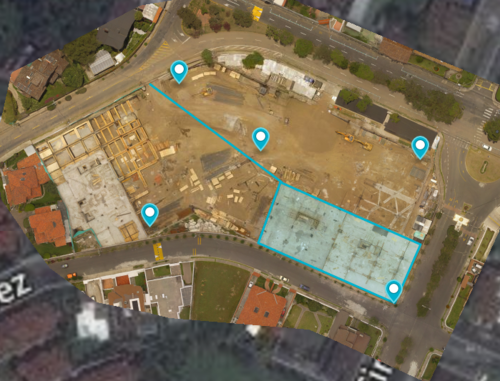
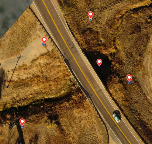
In the example, the subject of interest is not a square so we distribute the points as best we can in the corners and center. You can also see some other measurement annotations in blue.

Hello,

An interesting note about placing quality Ground Control Points.

Any other useful tips?

From groundcontrolpoints.com:

To make a quality ground control points to use for georeferencing in drone mapping software, there are 4 key things to remember.

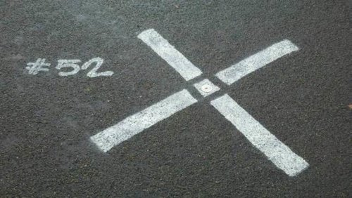
1) Use a Large, Clear Targets

Ideal GCP targets could be a large X marked on the ground, a checkerboard mat, or a circular target with a center point. You want to make sure your target has high contrast colors like black & white and that it is large enough to be easily visible from your flight altitude.

This is an example of a high quality GCP target spray painted onto the ground using a rectangular stencil.

circle-gcp-contour-lines.jpg?format=1000w

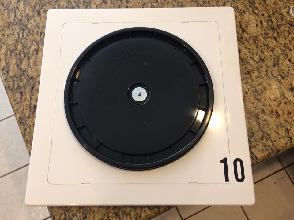
Another DIY approach we have seen is a 12" bucket lid stuck on a white plastic 14x14 access panel. Each of these are available at Home Depot, Lowe's, or your local hardware store.

3689713752?profile=original

This gcp was made with a sheet of roofing rubber ($4.66 each) and vinyl stickers ($1 per 6" x 12" sheet) to create a simple checker pattern that is highly weather resistant.


2) Measure Your GCP Center with High Precision GPS

The GPS on your phone, tablet, or drone won't cut it!

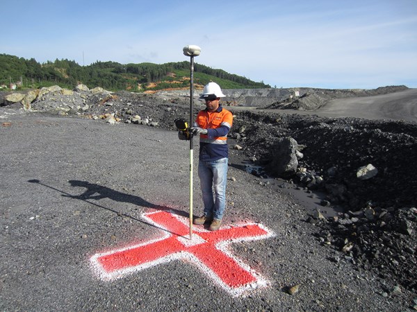
You need an extremely precise GPS measurement to create a quality ground control point. To do this you will need a Real Time Kinematic (RTK) or Post Processing Kinematic (PPK) GPS receiver. Traditional examples include the Trimble R family of products (including the Trimble R8 pictured on the right) but recently low-cost alternatives like the Emlid Reach have entered the market.

RTK GPS is required for GCP in mapping contour lines

RTK GPS is required for GCP in mapping contour lines

3) Evenly Spread Your GCPs Through Your Map

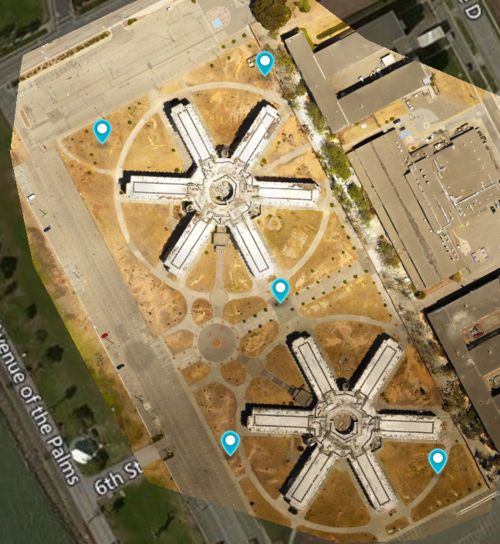
Typically you will need a minimum of 4 GCPs but no more than 10 are usually required even for larger maps. A good strategy is use 5 GCPs located in the 4 corners of your map and the center. As you place your GCPs make sure you leave a minimum 50 ft buffer from your GCPs to the boundaries of your map.

In this example, the subjects of interest are the 2 star shaped buildings so we place our GCP as best we can around the corners and in center of our subjects.

In this example, the subjects of interest are the 2 star shaped buildings so we place our GCP as best we can around the corners and in center of our subjects.

4) Make Sure Your GCPs are Unobstructed and Clearly Visible

To create quality GCPs for drone mapping, your markers must be clearly visible from your flight altitude to be successfully processed. Visual obstructions like overhangs, snow, shade, or glare can make your GCPs difficult to identify in your map photos.


Read more…