The above video shows how you can use Andruav for streaming video from your Drone(s), and receiving video simultaneously on different types of Andruav-GCS.
Although the video shows devices in one place, but you can make the same scenario using devices in different locations, even different continents, as long as they have Internet connection via ADSL 3G or 4G. Video quality depends on sender mobile, network and the receiver device.
The streaming protocol handles network bandwidth intelligently and adapt video quality according to bandwidth availability, also processing power of the receiving device determine video smoothing and glitches.
Giving current and expecting advances in technology in video streaming field and processing power, this should not be a problem in near future.
Please remember to use HTTPS when accessing Andruav Web Module to be able to access video.
Testing my implementation of global virtual airspace for autonomous drone navigation.
1. Grand Canyon, AZ, US
2. Sobótka mountain, S-W Poland (with a few airspace elements in the background)
3. Bellevue, WA, US
Blue net is USGL for symmetric navigation properties based on 10m DEM satellite radar and airborne LIDAR data.
Ground level is generated by obeying a few simple geometric principles that guarantee an automated system with specified climbing and cruise speed capabilities will be able to navigate safely in all directions (here 50mph, 1:10 climb slope, 1.12 max G factor).
It would probably be more spectacular a test flight of 4 hours but i was very interested in performing this test because it is very near to real use of Hybrix.20. 4 or 4.5 hours are possible for demonstration test but operational flight time is around 3 hours with light payload to 2 hours for heavy payload.
Lately many customers are telling us about electric multi-rotors flying for 2 hours or hydrogen fuel cells with 4 hours of endurance. It would be interesting to see these multirotors with heavy payloads.
Posted by Greg Dronsky on November 17, 2016 at 6:00am
Hi diydroners!
After a few months filled with hours of work we came up with the new version of affordable drone zoom gimbal solution for all diy users. We call it simply Vertigo V.2.
We listened to your feedback, which helped us in the biggest way possible, that is why there are lots of improvements laying underneath the new edition.
The V.2:
-We had a lot of emails with questions about different types of camera inside the gimbal. That is why V.2 is capable of containing several camera cores such as: 27X SD, 36X SD, 30X HD, 18X HD with video recording functionality, and 10X(with recording) + Thermal camera core, and more.
-We also made a gimbal version with increased yaw motor size which brings even more stability to the video than before. Now with the new aerodynamic design the gimbal is suitable to work on bigger aircrafts with cruise speed up to 60mph.
-The new construction and new material allows us to operate in high temperatures for as log as 8 hours with stable functionality all the time.
-The gimbal controller is now 32 bit board rather than 8 bit.
-We managed to upgrade the sensor so there is no I2C connection to IMU anymore, and the data is stable and reliable all the time!
-Overall, the gimbal runs smoother and the electronics are more reliable.
-All gimbal axis have physical end stops, for ease of use.
-We introduced first version of V.2 30X HD with digital image stabilisation
-We also introduced customisation service, that allows us to deliver better solutions for your projects
Vertigo V.2
We are making progress everyday, and we should soon be ready with new products. Here is a tiny sneakpeak:
Digital stabilisation test:
New lightweight 10x HD gimbal:
Thank you for you support:
We also want to thank you for last months together. We had the privilege to get in contact with you, and to learn about many of your incredible drone projects made all around the world.
Here are some of our memories from last months that we want to share with you, enjoy!:
- Our dear friend Tito with his awesome drones armada equipped with Vertigo 27X:
- Polish Airforce Institute Of Technology useing a custom Vertigo in their Atrax drone:
- RC Kozofsky, flying on a simple flame wheel frame and Vertigo 27X, a low budget system with great effects.
As we announced before, everyone that bought V27x is getting a discount on V.2, so if thats the case just email us (contact@vertigofpv.com) before the purchase and you will receive a discount code 150$. If you bought more than one unit from us please contacts us for special, even better offer.
We are looking for partnership and distribution right now, if you are interested please contact us we will be glad to make new business opportunities!
As always, you can find our products on vertigofpv.com
Posted by JeanLeFlambeur on November 16, 2016 at 11:30am
Here is the first test of my custom RC that will complement my custom FC and quad.
It uses a Raspberry Pi, 2x 2.4Ghz wifi cards for video streaming, a 433Mhz connection to control the quad and a 5.8Ghz wifi card to send the video to an android phone.
So far I have the hardware done - case, buttons, gimbal, screen etc - and most of the software in place as well.
Building a racing drone is always a compromise between low weight and high strength. Today’s typical racing drone design is based on lightweight and strong material – carbon fiber. Usually, it is an open frame made of a number of flat carbon fiber details, connected with bolts and nuts. Obviously, open electronic components are affected by the environment – sand, dirt, water drops. Such a set-up can be quite easily broken down during collision, crash or dive in the water. A drone pilot often has to bring two or more drones to the races, and spend a lot of time repairing them.
Nimbus 195 - is full carbon fiber monocoque frame, made as one continuous shell with a special technology. Monocoque design is widely used for example in aerospace and automotive industries (airplanes and car bodies).
Such design gives a number of special features which differs Nimbus from ordinary flat carbon frames: it is lightweight, enclosed strong and very durable body with high-quality aerodynamic form.
The first prototype with a frame size 220 mm, was made in January 2016, and was known under name of k-Pix 220, or Kolobok (a “bun”, fun and nimble hero or Russian fairytales).
After extensive tests, 20 units were delivered to pilots. Feedback was collected and used in the advanced design of Kolobok V.2, which got name NIMBUS.
We make the frame for Nimbus drone with a special technology, forming a carbon fiber “from the inside” in a cavity mold with a special bladder. As a result, we are getting seamless structure and a fundamental increase of strength, keeping the very low weight. The thickness of the shell walls is varying, depending on the stress level and stress distribution in that area. The stress level is considered during collisions with hard obstacles. In most stressed regions the thickness of the carbon is higher, in less stressed — lower, it varies from 1 to 4 mm. It is very efficient use of carbon fiber properties.
All electronic components of Nimbus drone, camera, and battery – are placed in this enclosed body and protected from the environment. And there are significant advantages, coming with enclosed and strong body, like:
- Extreme survival and endurance with perfect protection from crashes and collisions
- Super lightweight - varying thickness of the carbon fiber over the body to optimize strength-to-weight ratio.
- IP 54 ingress protection rating – protected from water drops and splashes getting inside the body
- Excellent aerodynamics given by efficient streamlined shape for omnidirectional flight. Minimum air resistance, high speed, and maneuverability.
What have we inside?
The RTF version will have a set of components proven by flight experience:
- 5″ props
- Newest F4 flight controller
- Powerful 2206 2600 kV motors
- 30/45 deg adjustable FPV camera HS 1177/1190
- On-screen display (OSD)
- Titanium fasteners for lowest weight and durability
- LiPo graphene battery 1300-1500 mAh
- Weight 310 g (w/o battery)
- Available as “frame only” and RTF versions
And it will be HD video-link ready for further upgrades. Such system like Connex Pro Sight fits into Nimbus body.
Of course, you can reach ultimate performance on any of mentioned features, make the lightest drone, or waterproof drone, or fastest dragster, or flying tank, but we were trying to have optimum balance for all features, and first of all to the benefit of a user – the Pilot. Enjoy your flying!
Nimbus Drone will have its campaign on Indiegogo platform started 1st of December 2016. Our campaign is aimed to raise funds for the establishment of the specialized high-quality production of hollow carbon fiber forms. We are starting with our first product - Nimbus Drone which will be ready for shipments in March 2017. If you are interested pushing racing drones design to a new level, or you are looking for new ideas – please, let us know and support our project!
Posted by Yan Roberts on November 15, 2016 at 8:49am
UAVs are making their way into the Internet of Things world. Drones are already deployable to distant places. For instance, DroneDeploy integrates telemetry devices into UAVs avionics. This permits to transmit data in real-time. It is possible to plan missions in a web-browser and upload tasks to your drone.
Drones may carry numerous types of sensors for multispectral and UV cameras, thermal imaging, microphones, and sniffers. PrecisionHawk creates a wide range of swappable sensors, you simply have to snap them into place.
Drones are reprogrammable in the mission. With SenseFly’s software, you can pick any place on the map redirect the drone, order it to accomplish an alternative mission, after that resume and do the initially programmed task, etc.
Drones are also effective at measuring everything and wherever you need it. Like in the case with LiDAR (Light Detection and Ranging). At the GIS market, you can find high-performance UAVs capable of doing unmanned distant laser scanning.
Present day drones incorporate many things in order to fly: ground control stations, avionics, communication systems, processing and data collection software, and certainly GPS. They are multifunctional flying vehicles that can be called IoT in motion.
Cyber security risks of IoT and drones
Cybercriminals change their focus to a new malware variety roughly every three or five years. The biggest cyber threat of the present day is called ransomware. Ransomware authors infect devices, encrypt valuable data and then ask to make ransom payments.
After initially targeting individual computers the next wave of ransomware attacks does not go for our data files but instead our IoT devices. UAVs are exposed to these risks more than ever. This ransomware transformation makes it more damaging and harmful due to the special nature of IoT security.
Besides their anonymity, the major strength of the most successful ransomware such as Thor is their irreversibility. These viruses use unbreakable RSA and AES crypto. Victims have no other option than to pay if they want to get their files back.
Some may think that if IoT devices store minimum or no data at all, that makes them economically unprofitable to ransomware authors. It is not really so. IoT ransomware may turn off cars, burn your home, or stop manufacturing lines. This prospective to bring greater destruction and problems indicates cybercriminals will be able to demand larger ransom sums, turning ransomware into an attractive marketplace to dive into.
You may say that IoT hacks may very well be stopped by a quick product reset. It is not the case here, people are going to pay not because they may just loose (sometimes cheap Chinese) drones forever but rather because of potential harm and losses in the event of inability to use their devices for any period of time. Like in the case with thermostat - you may lack valuable time to get home to prevent it burn you house.
Extrapolating ransomware on UAVs a bit more, imagine you want to make photos of your neighborhood. After several successful shots, the hackers begin blackmailing you into paying a ransom threatening to put photos online for your neighbors to see themselves naked. Your drone is in the sky, possibly not visible, and already not responding your commands. Even if you do not care about its price and ready present it to crooks, you should care about neighbors’ photos.
It is still early to declare the IoT ransomware is already a big threat. The IoT firmware and UAVs, in particular, are fragmented, usually missing standardized processes, communication, and operating systems. Each new offense may affect only a certain kind of device. This fact substantially decreases the quantity of objects that may be attacked simultaneously. However, this condition is sure to change in the upcoming years and maybe months, since IoT tends to be more widespread.
Protection
Any IoT gadget is not made to stay secure all the time, it should be patched and updated. And it should be done securely, otherwise, update signals may themselves turn into channels to invade systems with viruses.
Secure updating implies locking the firmware and processor and encrypting the communication. There is a strong reason to use solid authentication techniques to minimize IoT cyber assaults. In many situations, IoT products are not even authenticated, which makes them easy to spoof.
For now, the bad guys are still researching the potential economic value that IoT viruses can possibly provide. At the same time, security attempts made by creators and adopters of IoT tools leave much to be desired.
Cyclocopters get particularly interesting at very small scales because of their combination of very high maneuverability and potential for excellent efficiency. They have experimentally demonstrated the higher aerodynamic efficiency (thrust per unit aerodynamic power).
Do you have any data on this "excellent efficiency" ?
Dimensions 8 mm x 5 mm Peak optical output 85 W at 30 A per channel Wavelength 905 nm Pulse length < 5 ns Operating voltage 24 V
The overall lidar system covers 120 degrees in the horizontal plane, with 0.1 degree of resolution, and 20 degrees in the vertical plane, with 0.5 degree of resolution. In the light of day, it should detect cars from at least 200 meters away, and pedestrians at 70 meters out.
The MEMS chip can operate at up to 2 kilohertz
The company says test samples will be available in 2017, and that commercial models could arrive in 2018.
With mass production, the price should drop to around 40 Euros (US $43.50)
I banged my head against a while for a while learning to share drone data in Mapbox and, now that I've got everything figured out, think it is a lot of fun and I thought I would share lessons learned on DIYD. Unfortunately, running JavaScript from within a blog post is non-starter, so you will have to cruise over to my blog to check out how some of these things actually work. All of the images here are just static representations of the interactive maps.
Autonomous flying vehicles capture all kinds of interesting GIS data–photos, projected photos, and flight logs, to name a few. Furthermore, drone imagery can be processed into other GIS data products like orthomosaic images and point clouds that become infinitely more valuable when combined with traditional GIS data sources like property boundaries and civil engineering diagrams. That said, sharing these data off-line is quite challenging. Massive geotiffs are painful to open in heavy GIS software like ArcMap and QGIS, individual images are troublesome to keep track of when not associated with a map, and flight logs are near useless in their raw .tlog or .bin form. Our friends at Mapbox have assembled an incredible (and free up to a substantial quota) toolkit for sharing all of these data in a simple webview format.
Follow these instructions to create an interactive map showcasing your drone data like the one below, whose source code is available at https://github.com/dmckinno/Mapbox. For this particular example, I overlaid a property boundary and fantastical building footprint kmls, an orthomosaic geotiff, and a handful of images viewable by clicking on the location at which they were taken, but essentially any GIS vector or raster data are sharable using Mapbox.
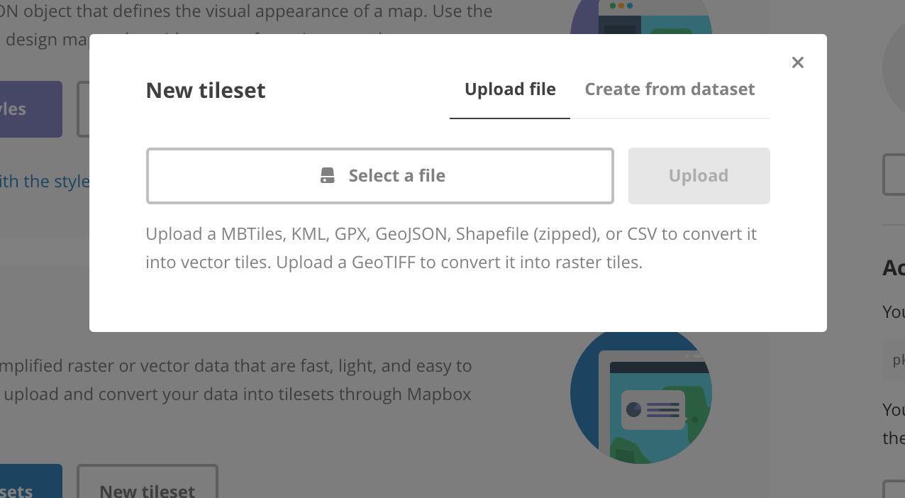
Open Mapbox Studio. If you are not interested in adding interactivity to your maps, you can share all of your drone data without writing a single line of code. Simply upload your data a a tileset and add your tileset to a style
.
Mapbox accepts raster data in the geotiff format and vector data in the kml, which can be generated from Arducopter .tlogs using Mission Planner, gpx, which is the standard output from handheld GPS devices, GeoJSON, a GIS standard that is easily passed between systems, .shp, an open ESRI format, and .CSV formats. After uploading any of these file formats, Mapbox will slice the data into either vector or raster tiles that can be beautifully navigating on the web.
Note you are unable to display a single nadir photo or a point cloud using Studio. To display a single nadir image in Mapbox, you must write a few lines of JavaScript (see below for examples). If you would like to display a point cloud, you must first use laslib or a commercial tool like ArcMap to convert to a geotiff.
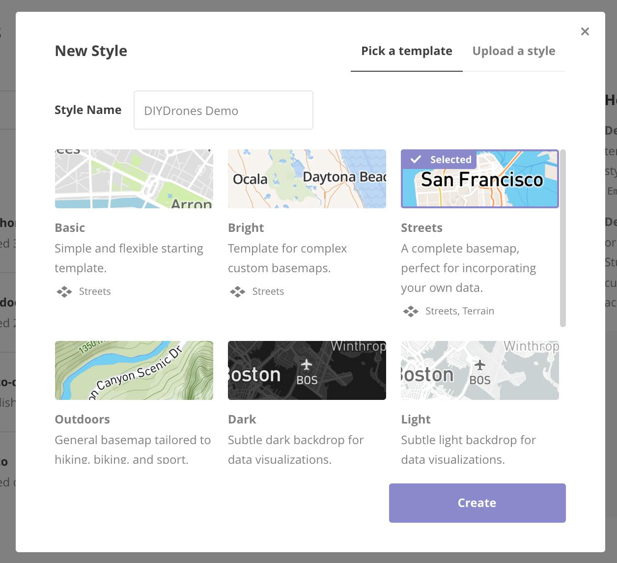
Once you have uploaded your tileset, create a new Style.
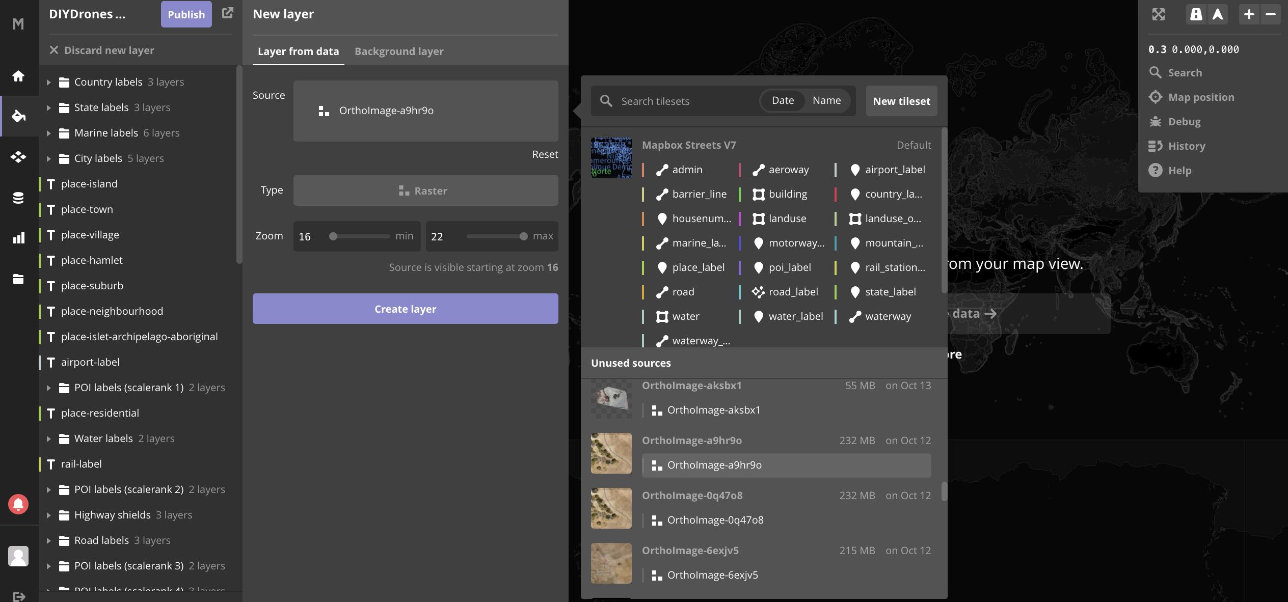
Choose the desired basemap, add your tileset(s) to the map, and click “Publish.”
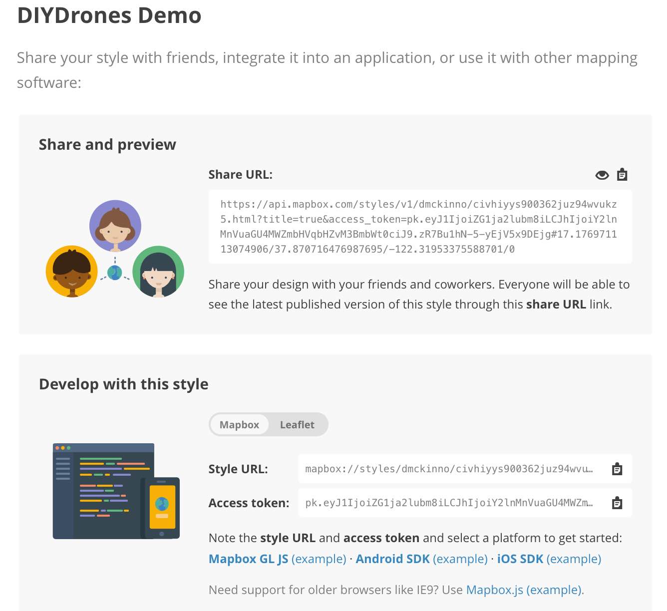
Mapbox will take you to the “Preview, Develop, and Use.” Copy and paste the generated URL and send it to all of your friends. This particular example is available here.
Tilesets uploaded via Mapbox Studio cannot be manipulated by the user viewing them in the browser. To build the types of interactivity that I showed in the example above, you must write a few lines of JavaScript.Fortunately, this is quite straightforward and nicely mirrors the GUI options in Studio. To add a layer, use
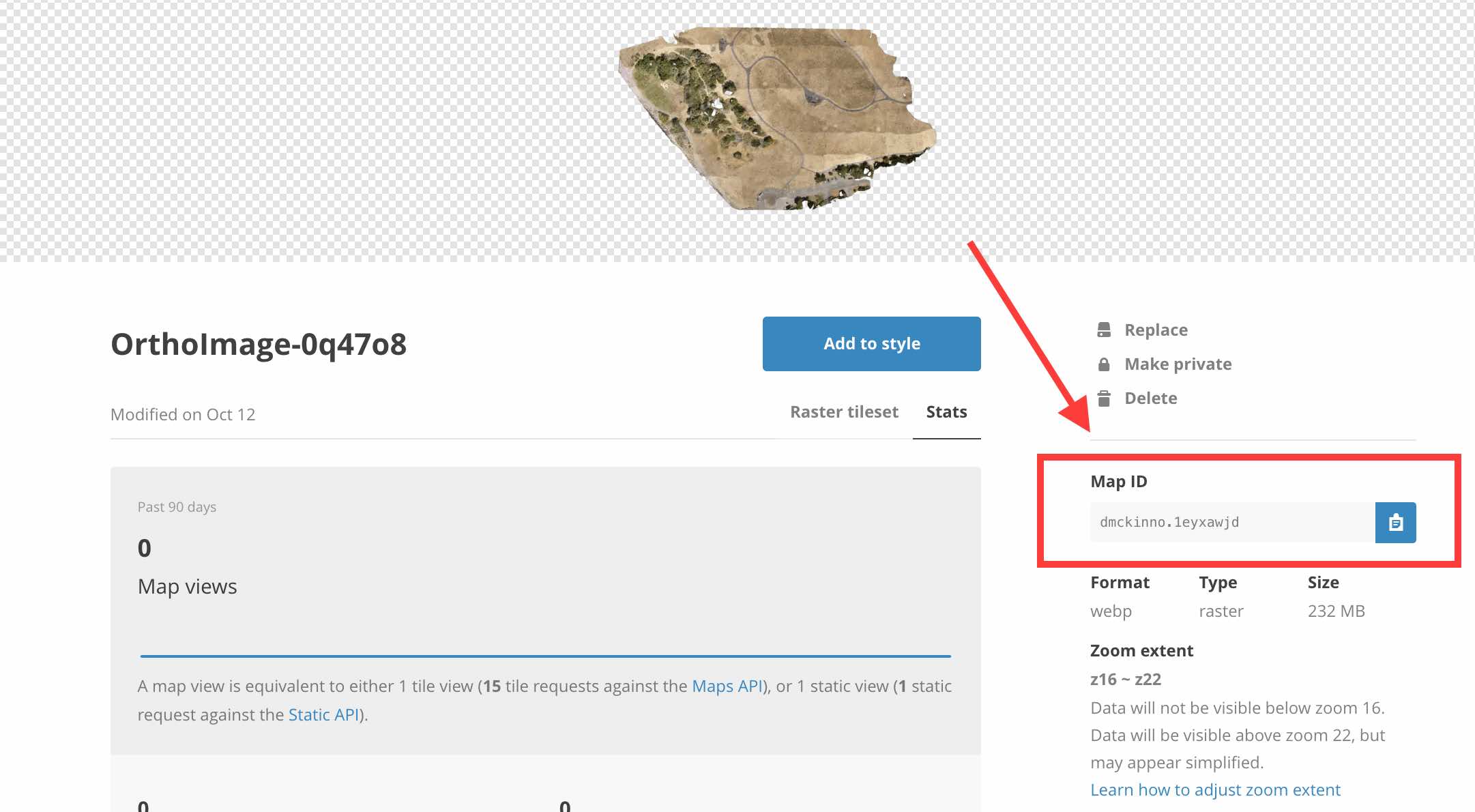
This is a combination of the map.on and map.addLayer functions. I don’t know enough about JavaScript to explain exactly why they are both needed, but they are always together. I believe a layer is created and then placed on the map. In this case, I am adding a raster from a given Mapbox URL (this is creating by concatenating mapbox:// and the Map ID shown inside the tileset view) and placing it on the map with the ID “ortho.”
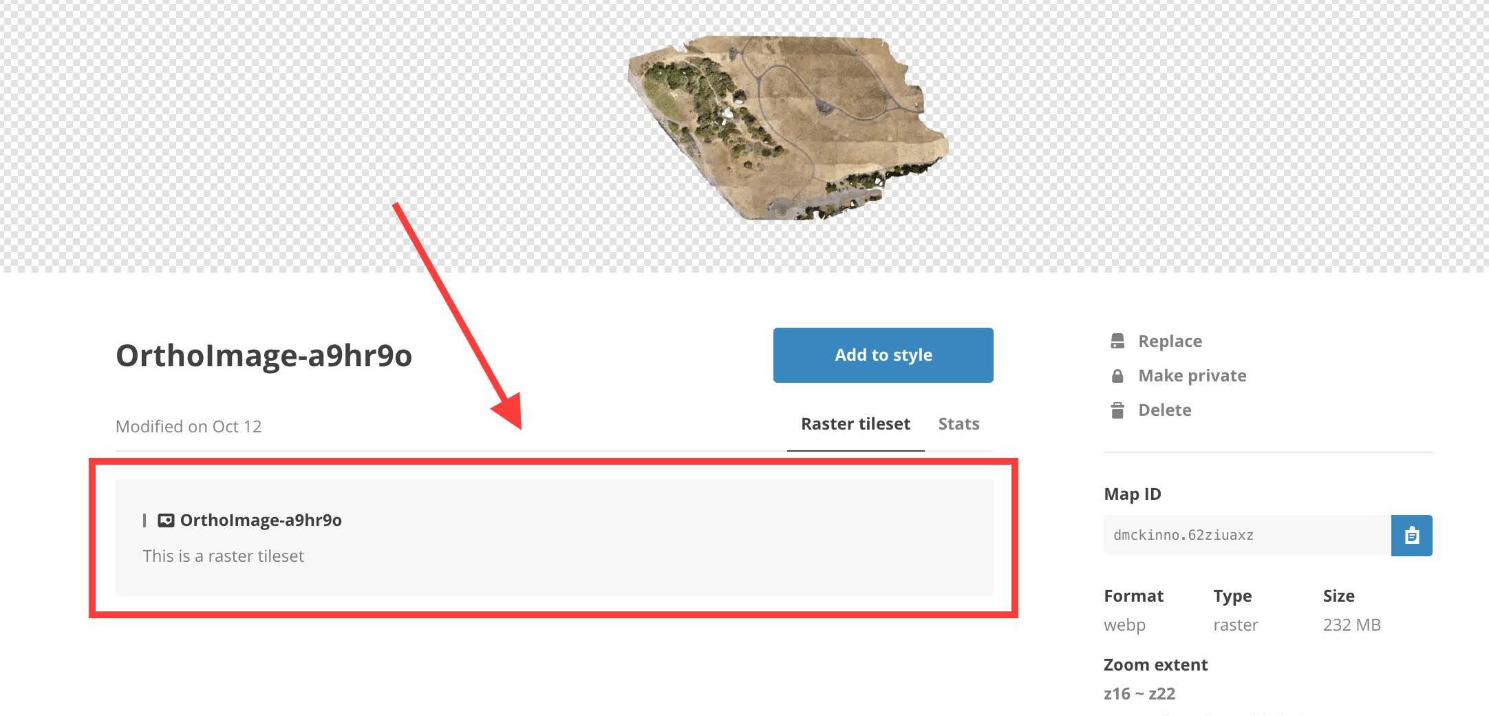
I always keep the source and the ID the same, but I’m sure some Mapbox wizard understands why they may be different in certain cases. The source-layer comes from the individual layer within the tileset. The is irrevelevant for rasters, but important if a vector tileset contains several different features. Nonetheless, the source-layer is available in the “Raster tileset” or “Vector tileset” tab in the tileset view.
The only differences arise in the options available for displaying the data beautifully. Vector data can be painted with different colors, thicknesses, fills, and opacities. Here, I simply drew white circles that indicate photo locations, but more complex vector layers can be displayed in infinitely complex and beautiful ways. The Mapbox documentation walks through the options in painstaking detail.
Now you have your orthomosiac and raster data loaded, but you may want to augment the orthomosaic with individual nadir images. If you calculate the coordinates of the four corners of the image using the altitude of your drone and the focal length of the camera using simple geometry, you can display nadir images as psuedo-orthomosaics using the code below.
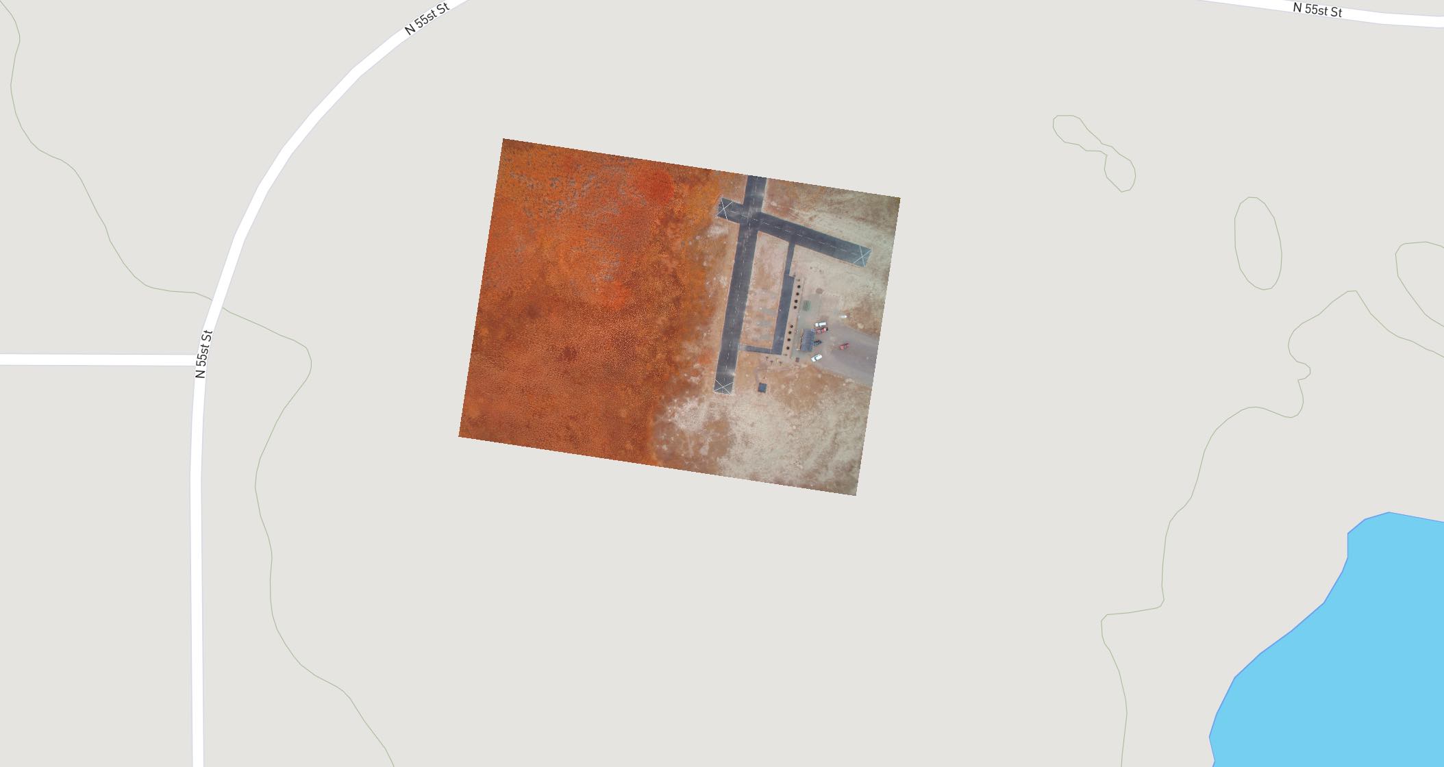
It is somewhat challenging to embed two Mapbox maps in a single WordPress post (I use Code Embed, but please let me know if a better way exists), but an interactive map is available here and an image preview below. Note that because the image is not tiled, it is much less responsive than a true tiled orthomosaic.
The final vector layer type you may be interested in displaying is a image locations. It is often helpful to show where images were taken on a map and be able to view them based on context, whether project appropriately on the basemap or not. To do this, you must create a .kml, .shp, or .geojson file from image EXIF data. If you only have a few images, you can easily do this manually, but if I would recommend using the exif-to-geojson tool for more than a handful.Once you have the geojson file containing all of the photo information, add a description field with the image URL and any text you like to each image. You can see another nice example of this in the map of my motorcycle trip.
“data”: { “type”: “FeatureCollection”, “features”: [{ “type”: “Feature”, “properties”: { “description”: “<img src=”YOUR IMAGE URL HERE”> and any text or links you like” }, “geometry”: { “type”: “Point”, “coordinates”: [YOUR LONGITUDE, YOUR LATITUDE] } }] }
Now that you’ve added all of your layers, you likely want to include some interactivity. I’ve played with all of the Mapbox examples, but most relevant here is the ability to show and hide layers and show images upon a click. For my example above, I copied and pasted from Mapbox with minor modifications and I recommend you do the same, making sure that you grab every line that you need.
And voila! Now you have all the tools you need to share your drone data with all of your friends and followers using Mapbox and a few lines of JavaScript.
I love this young and smart team, who came out of University of Kansas and are doing very cool work with FPGAs. From sUAS News:
Aerotenna, the leader in radar sensing and SoC flight control technologies for UAVs, has won first prize at the Unmanned Traffic Management (UTM) Preliminary Drone Sense & Avoid technology competition held on November 9 in Syracuse, NY. The competition was launched by a partnership between UTM Convention and HiddenGenius.com to demonstrate drone sense and avoid technologies in an open competition to build public trust.
UTM Convention 2016 is held November 8-10 at the Oncenter in Syracuse, NY. The annual event brings together aerial technology leaders from around the globe, including experts from the FAA and NASA, to explore the latest technical capabilities and discuss collaboration to rework the global airspace in the next era of aviation. The Drone Sense & Avoid technology competition was held during a Google-sponsored reception in front of leading companies and organizations including Google, Intel, Amazon and NASA, as well as drone industry regulators, investors, and most importantly the public.
Sense and avoid is a critical technology that enables safer and wider usage of drones in many applications such as monitoring the safety of bridges, rail lines and other critical infrastructure, delivering packages, and humanitarian missions. The competition obstacle course was designed as a mini replica of environments and scenarios drones would face in the real world, including a miniature bridge, glass obstacle, replica power line, and moving obstacle. More than one thousand in attendance watched as Aerotenna demonstrated its collision avoidance solution based on the μSharp sense-and-avoid radar and the OcPoC SoC FPGA flight controller. Aerotenna successfully completed two collision-free rounds in the fastest time to take home the $12000 first prize.
The development of sense and avoid technology is also critical for the flight of drones beyond visual line-of-sight and into national airspace. Aerotenna recently announced the release of a new miniaturized collision avoidance radar and SoC flight controller for all drone platforms. Radar’s robustness and reliability in all-weather, all-terrain and all lighting conditions make it an indispensible sensor for autonomous smart drones. Until recently, radar has not been considered a practical sensing solution for small UAVs due to size, weight and cost. With a suite of robust yet affordable and easily integrated sensing and processing solutions for all drone platforms, Aerotenna is positioned to be a key solutions provider in the commercial and consumer drone industries.
“Advancements in drone sensing and processing technologies are making autonomous drones a reality, and open competitions such as the UTM Drone Sense & Avoid competition are great venues to show the public just how smart drones have become,” said Dr. Zongbo Wang, CEO of Aerotenna. “The capability of Aerotenna’s collision avoidance radar shows the power of radar as a robust, affordable and easily integrated solution for all drone platforms in the new era of aviation.”
The Ungulate Disease and Damage research project of the National Wildlife Research Center acquires the Aeromapper Talon to test for mapping and precision agriculture
The Ungulate Disease and Damage research project (USDA APHIS division) has selected the Aeromapper Talon for their research on surveying and mapping agricultural areas that have been damaged by wildlife. Among the different payloads offered with the Aeromapper Talon they have chosen the standard 24 Mp RGB Sony camera as well as the Micasense Rededge multispectral camera. The cameras are easily swappable on the UAV.
They have decided on the Aeromapper Talon because it offers a very unique set of characteristics, like:
- Interchangeability between the RGB and high end Multiespectral cameras like the Micasense RedEdge
- Long range communications link
- 80 mins endurance
- Fully autonomous flight
- Ease of use for operators with no previous experience
- Modularity and affordability of parts
- Mission editing while in-flight
- Operations in tight areas thanks to its impressive climb rate and easy handlaunch
- Parachute recovery
- Reasonable price of the entire UAV system
- Proven track record
- Return to home upon loss of link
- No experience or training required
- Each and every unit is flight tested before delivery
Alternatively, the Aeromapper Talon offers optional GNSS PPK upgrade, dual camera configurations like:
- Sony 24 Mp RGB and Parrot Sequoia onboard at the same time
- Sony 24 Mp RGB and Flir
About Aeromao
Aeromao Inc, is a Canadian leading UAV manufacturer, developer of the Aeromapper series of turnkey unmanned aerial vehicles for mapping, surveying, precision agriculture and remote sensing.
With exports to more than 45 countries in less than four years after founding, Aeromao Inc. offers a line of products that adapt very quickly to market demands and to unique client's applications, where no other UAV manufacturer goes. From wildlife monitoring in the Artic (by University of Alaska Fairbanks) to water quality monitoring in Saskatchewan (by Environment Canada) the Aeromappers have been used by corporations, research organizations, universities and government agencies around the globe for a great variety of applications.
We have just implemented a major upgrade to the ArduPilot sensor drivers for STM32 based boards (PX4v1, Pixhawk, Pixhawk2, PH2Slim, PixRacer and PixhawkMini).The new sensor drivers are a major departure from the previous drivers which used the PX4/Firmware drivers. The new drivers are all "in-tree" drivers, bringing a common driver layer for all our supported boards, so we now use the same drivers on all the Linux boards as we do on the PX4 variants.We would really appreciate some testing on as many different types of boards as possible. The new driver system has an auto-detection system to detect the board type and while we think it is all correct some validation against a wide variety of boards would be appreciated.
Advantages of the new system
The new device driver system has a number of major advantages over the old one * common drivers with our Linux based boards * significantly lower overhead (faster drivers) resulting in less CPU usage * significantly less memory usage, leaving more room for other options * significantly less flash usage, leaving more room for code growth * remote access to raw SPI and I2C devices via MAVLink2 (useful for development) * much simpler driver structure, making contributions easier (typical drivers are well under half the lines of code of the PX4 equivalent) * support for much higher sampling rates for IMUs that support it (ICM-20608 and MPU-9250), leading to better vibration handling
.....
see the posting on discuss.ardupilot.org for more details on how to participate in testing.
Hello! Our Friend Bagus Darmawan from Indokopter (from Indonesia) has made this video where he demonstrates his integration of the North's RTKite GNSS RTK Double Frequency L1+L2 Receiver (http://northsurveying.com/index.php/instruments/gnss-rtk-receiver) into a Microkopter frame receiving RTCM3.x RTK corrections from a ground Base, a North SmaRTK GNSS receiver (http://northsurveying.com/index.php/instruments/gpsrtkreceiver), broadcasting by GSM / GPRS mobile network using our P2P Autocaster technology for professional photogrammetry on a fully controlled shutter. We think is a superb example!
This was part of his Thesis comparing the standard L1 GPS, L1-Only RTK and L1+L2 RTK into photogrammetry, we think this is information that would be important to all, so you can review the full document here!: RTK UAV Photogrammetry Thesis
The RTKite L1+L2 receiver allows the drone to capture geotags with millimetric accuracy (4mm +/-1 RMS) thus elliminating or reducing the need of GCP greatly.
We have just simplified the camera integration with this ready-made kit:
The SmaRTK receiver, is a fully integrated rugged L1+L2 RTK receiver, ready to broadcast corrections by Mobile Phone networks, UHF datalink or the user's own RF, it actually has the same GNSS capabilities as the RTKite and can be used to locate millimetrically the GCP and connect to CORS stations worldwide, or be a CORS station itself, with a great price!
A full photogrammetry system -professional level- can then be integrated at around 15-20,000usd and can be easily compared to systems on the range of 50-70,000usd commercially available.
This is a sample of the data output of the RTK working in real time at 10Hz, being corrected from a CORS station at 1Hz or less: RTKite Data output test.
If you want to see, order or test the RTKite for your projects, we now have a direct webstore accepting credit cards!, just visit here: http://www.gnssrtkmodule.com/
All our instruments are designed, produced and shipped from Barcelona.
After months of work and rewriting the app from the ground up, we are ready to introduce you to the new ReachView generation. Over the past year Reach has become an incredibly popular device and we want the software to be up to par with the hardware. We've used the past year's experience and user feedback to rebuild the app. This update focuses mainly on general stability, user experience and usability. We got shiny looks too
Changes
User Interface
Completely new beautiful UI
Dashboard with all important information
Integrated maps
Contextual hints
RTK settings simplified
Streams now show connection status
GNSS visibility predictor
Every field has validity checks
Back-end
New back-end handles RTKLIB
Robust performance
Base station mode
Now Reach can operate both as a rover and a base without mode switching
Automatic base coordinates by averaging single position or RTK Fix position
RTCM3 messages rate can be adjusted individually
All RTCM3 messages now have comments
Bluetooth
Completely reworked bluetooth
Supports COM port to Windows
Works more robust with Android
Bidirectional communication
Ability to disable Bluetooth RF
Wi-Fi
Completely reworked Wi-Fi
We don't relu on Intel's software
Add/remove networks from within the app
Connect to any of known networks
Switch to hotspot mode
Device name now can be changed
Ability to disable Wi-Fi RF
Hotspot password can be changed now
Memory
More memory is available for logs
Base now logs raw data
Automatic log split
Rolling logs support
Update process
Now a dedicated app handles updates
Update system using packages
You can see if a new version is available
Bug fixes
Fixed kernel crash if UART radio talks during boot, leading to device not booting.
Kernel options for 3G modems compiled into the image
Fix SPI for robust IMU reading
New self tests compatible with M8T 3.01 firmware
Known issues and missing features
The app is not suited for multiple users working at once. It will misbehave heavily if open in several browsers simultaneously
RINEX logging. Users can download ubx raw data log files and convert them to Rinex using RTKCONV utility. Soon we will implement on-the-fly conversion and compression. That will save memory and get rid of a separate conversion process
USB connection. USB has been reworked in order to support COM port creation on Windows when connected as a client, but USB features did not make it to this beta. Radio over USB will not work for now.
No progress bar during update process. Update takes about 2 minutes, depending on your internet connection. Please be patient, we know this is hard to endure
After doing the first setup and rebooting, ReachView may experience a problem with a browser's cache. You might see the main chart missing. To fix this, refresh the page. If that does not help, clear browser cache and refresh again.
What's next?
We are actively working on bringing new features to this beta release. Here are some of them:
I'm excited about this, not least because Aero will support the Dronecode stack out of the box. From PC World:
Intel in December will start shipping a fully loaded drone kit to let you do just that, with all the parts including the rotors, software, 3D camera and flight controller.
Intel's Aero Ready to Fly Drone kit will go on sale on the company's website. An Intel spokeperson couldn't immediately provide a price. But it won't be cheap—likely more than $600.
The quadcopter kit has parts that Intel uses to build its own drones. On the company's part, the drone airshows it has organized are getting ambitious: the company has put up 100, and most recently, 500 drones in the sky.
Drones themselves are getting sophisticated. DJI's Phantom has chips and 3D cameras that can navigate safely while avoiding collisions. The Intel Aero Ready to Fly Drone kit has the 3D RealSense camera, which can measure distances and recognize objects and help the drones, when programmed correctly, to fly autonomously to a given destination.
The 3D RealSense camera attaches to a central computer called the Aero Compute Board, which gives the drone its computing horsepower. (Intel also sells the Aero Compute Board separately for $399.) It is powered by a quad-core Atom X7-Z8700 CPU code-named Cherry Trail. It also has LTE, 802.11ac Wi-Fi and a flight controller. The board also has 4GB of LPDDR3 RAM, 16GB of flash storage, a micro-SD slot, a micro-HDMI port, and a wide set of connectors for adapters and breakout boards. It also has the Altera Max 10 FPGA, which can reprogrammed for image recognition, navigation and other deep-learning tasks.
The drone will work with the Airmap software development kit for navigation. Programming will also be required to put the drone in the air. For example, you can use the RealSense SDK to program image recognition for the 3D camera.
An overview on how to build drones from the recent Embedded Linux Conference Europe 2016 is available on Youtube.
The kit will ship in some countries in North America, Europe and Asia. For U.S. buyers Intel has included a caveat relating to government regulations on requiring authorization to fly drones.
Sky-Drones is introducing SmartAP RTK, this is a perfect addition to the flight controller when positioning precision really matters, it provides centimeter level accuracy. The system is based on the latest UBlox Neo-M8P chipset and is fully integrated across all SmartAP flight controllers and software. Standard telemetry is used to send RTCM corrections via SmartAP GCS.
Real Time Kinematic (RTK) satellite navigation is a technique used to enhance the precision of position data derived from satellite-based positioning systems (global navigation satellite systems, GNSS). It uses measurements of the phase of the signal's carrier wave, rather than the information content of the signal, and relies on a single reference station or interpolated virtual station to provide real-time corrections, providing up to centimetre-level accuracy.
Specifications:
Centimeter‑level GNSS positioning
Integrated Real Time Kinematics (RTK)
Smallest, lightest, and energy‑efficient RTK module
Complete and versatile solution due to base and rover variants
World‑leading GNSS positioning technology
UBlox NEO M8P chipset based
25mm ceramic patch antenna
GPS / GLONASS support
Up to 24 satellites
8 / 5 Hz update rate (GPS / GPS + GLONASS)
Rechargeable 3V lithium backup battery
Ultra-Low noise 3.3V regulator
Power and fix indicator LEDs
Exposed RX, TX, 5V and GND pads
Integrated magnetometer on airborne module - HMC5883L