Check out the new video on Skysense Planner - An Open-source Web Mission Planner for MAVLink Drones, including ADS-B aircraft tracking and Geofence management: https://vimeo.com/180557422
The PX4 Pro flight control stack offers fully autonomous control of VTOL airframes including delta quads and planes, tail sitters and tilt rotors. Special thanks go to Droneslab for the airframe and UAVenture for the ongoing software development collaboration.
Posted by Gary Mortimer on August 26, 2016 at 11:05pm
Of course, you are always careful you are a DIYD member.
We are all aware of Part 107 coming in next Monday. The very simple test that will allow folks to fly commercially. Less is being said about Part 101, the bit that affects all other model aircraft fliers. If after Monday you don't have a Part 107 ticket, that's you. I speak with Loretta Alkalay ex-FAA legal she was there 30 years.
If you listen it's not just Monday either, they can come after you retrospectively. The grey area in which folks have been flying has been coloured in.
There are things going on in the background to address some of the issues that are coming up but just be careful of any FPV you post or log files that demonstrate BVLOS flight.
APM Rover on VR Brain 5.2 + Companion Computer + ROS and Slam mapping the navigation in outdoor done without GPS but the feedback is aligned with Geo Map because we use the GPS offset and Mag offset as starting point ... Today was our first test without gps and it work fine ... The rover need some hardware patch and fine tuning setup but the algorithm work fine :)
On Ground station you can work as with the GPS all functionality are available , in the next months will be release the anti collision module already integrated in enviroment available for pro user in all Ardupilot enviroment and firmware.
This is a core technology that we share on all Ardupilot firmware : Arducopter ,Trad Hely , Arduplane ,Ardurover and Boat.
Some people told me to switch to PX4 but for use better ROS integration although VR Brain hardware already support PX4 but i prefer to improve the integration of ardupilot firmware our team have a great skill and the Dev Team of Ardupilot are my old friend start to work togheter 8 years ago :) and we have a lot of advanced functionality already available for indoor localitation that we use with our customer and not only inside the university lab.
So is possible use Ardupilot for professional application. Thousand of users around the world use it .
So actually we are working to Pro version of Ardupilot fully integrated in ROS and available as modular firmware and hardware object , in the next week we discover a lot of great project develop on Ardupilot Pro pro on VR Goliath platform.
Thanks to whole Ardupilot.org DevTeam for all work done until now on ArduRover
P.S.
the video is intalian . but is at 360 degree . It's a standard working day in our lab ... ;)
Interesting OpenSource project that use only a simple RaspberryPI 0 as DVB-S transmitter + RTL-SDR dongle as receiver. This is less expensive DVB-S trasmitter ever developed. All the project is by Evariste he is a great developer and member of HAM Radio community ... now we are working togheter to a revision of system with low latency that fit the requirment of drone community .... now the latency is 2.5 second could became 200 ms with a power ampli for real use in outdoor scenario. If some one would join to beta testing of the system are welcome :) This is the github where you can found the source code of the project .https://github.com/F5OEO/rpidatv
The receiver is an RTL-SDR standard dongle available on store like amazon or ebay for price less 30 $ . The decode is done using SDR technology the software from decoding is from Pabr the name is leandvb . This is the link .
Last year I was searching how to fly at safe low altitude to take the higher resolution photos that possible, to identify weeds and insects in crops and trying to know if a laser altimeter can do the task, first I bought a Lidar lite but looks unstable over rought terrain perhaps bad installed or configured and no more support to ask, but, in the way, Laserdeveloper offer me to test the SF11 and send me one, I was little nervous because I'm not have much electronic knowledge, I couldn't make Lidar work yet, and SF11 looks more professional with PC connection and configuration capable, but results an RTF tool, very easy to install, Pixhawk configuration I use as instructions said, I use serial connection http://ardupilot.org/copter/docs/common-lightware-sf10-lidar.html?highlight=sf10 and SF11 configuration I don't change nothing but have many things for different tasks, standard ones looks nice for me.
It have an intuitive software to test with the pc too, you plug to USB with provided cable, open the program and look readings, I them took a ruler and measured the SF11 with the floor and looks near perfect :O ; many rainy days them (I'm in winter :( ) I did a first little fly with strong wind, the wind hit the copter but altitude didn't change, a better day I can fly more to test and take this video flying over a rought terrain; I'm going to test over different crops with different stages, and different slopes to see what happend.
Thank's to Laser developer to give me the opportunity to test this great altimeter :D
Posted by Paulo Neves on August 25, 2016 at 9:30am
Here at Airborne Projects we have been hard at work with new ways to bring MAVLink telemetry to the ground without extra parts. Specifically we are working on an Antenna Tracker that needs information about the whereabouts of the Drone, but this is for another post.
Because of our needs for wireless DRONE position information without the extra radio link we have developed a module that connects to the external module compartment of the Taranis Plus and retrieves the Frsky telemetry our Airborne Projects converter sends to the ground through the SmartPort protocol. This module transmits through Bluetooth the MAVLink data and in the video below you can see this working with DroidPlanner application in Android.
This converter is receive only, as the SmartPort as far as we know does not allow for sending.
We are able to reconstruct many messages from the information our converter sends to the ground, but even so we have been testing sending extra information through unmarked sensor IDs. This is going to be available with a free of charge firmware update to our customers.
Below is the data MAVLink data which is populated by our telemetry module:
At PropellerAero we think it is too hard and expensive for commercial drone operators to capture survey grade data - we needed a solution which was separate from drone or camera, and didn't require expensive GNSS rovers out on site.
Today we are launching our new AeroPoints - easy to identify ground control targets with built-in PPK to capture very accurate (~2cm in X,Y, 3cm in Z) positions to georeference your aerial surveys.
The units are fully solar powered, water-resistant and last weeks on the inbuilt LiFePO4 Battery.
We have been working on the concept for the last 18 months - and the accuracy we are getting is pretty exciting:
The AeroPoints correct off local RTK basestations, and we currently have coverage across AU, USA and the UK, with more countries coming online shortly. In areas outside RTK correction zones, the AeroPoints use a complex mesh algorithm (like PPP) to correct the position data, giving <1cm internal accuracies and decimeter-grade global accuracy after a few hours of recording.
This mesh algorithm gives our AeroPoints much greater usable baseline lengths than traditional, instantaneous RTK as well - as we measure the same point from more distant base stations the difference from the Topcon control remains tolerable:
Post survey, the AeroPoints look for a wifi hotspot (SSID: "propeller", password "propeller") and will connect automatically to the Propeller servers and upload all their information, where we then tie against local CORS data and generate highly accurate points.
For those who already use the Propeller platform for processing and visualisation, the AeroPoints will automatically tie down your data - and for those who use desktop processing (pix4d/agisoft), we output a PDF report of qualities and a CSV block ready to go straight into your workflow.
A set of 12 runs for $6000 US, good for 150Ha (370acre).
Really looking forward to improving data accuracy across the industry: coarsely georeferenced information being used for technical applications is particularly frustrating for us at Propeller!
You may have seen reports about SolidEnergy's batteries that use a new type of Li-metal anode which enables a doubling of the energy density of lithium batteries. I looked into it some more and found their first market is going to be drone batteries, this November. The article says "some drones" will be able to use this battery in November. Not sure what that means exactly. I hope "some" includes my Iris+!
SolidEnergy ... innovates at the materials level, not the manufacturing level, but the batteries enabled by its materials can be manufactured using existing Li-ion manufacturing capability. This allows it to avoid massive infrastructure investment duplicating what the industry already has, leverage an established ecosystem, and efficiently capture the highest value.
SolidEnergy... acquires and processes raw materials from its strategic partners in chemical and equipment manufacturing. The company develops two key enabling battery materials: the anode, which consists of anode-lyte coating on lithium/copper; and the cathode-lyte (anode-lyte and cathode-lyte are two components of electrolyte), which consists of salts, ionic liquids and other chemicals. These two battery materials are then supplied to the battery manufacturers with a separator and a cathode to form complete batteries. SolidEnergy does not manufacture batteries, instead it provides key enabling battery materials.
I'm hoping this means they'll have no production bottlenecks, they'll be licensing out the technology to all our favorite battery makers, and by Christmas I'll be able to fly my Iris+ for 30 minutes with equipment attached.
MAVLink Compatible Protocol Can be used with Mission Planner, Qgroundcontrol, UgCS (v2.10) Free 50 waypoint navigation included Total solution for all multicopter platforms Flight Control Mode: Manual, Attitude, GPS Enhanced Lost-Control Protection: Return to Launch (RTL), Auto Hovering Augmented Control Mode (ACM): Point-of-Interest, Stick-Orientation, Home Steering Compatible systems: Futaba S-Bus, DSM2, DSMX, JR XBus, JETI EX Bus, SRXL Integrated Bluetooth module, Mini-USB Onboard Data Logger User Updatable Firmware
ELECTRICAL SPECIFICATIONS
Operating Voltage: 4.5V~8.5V Current consumption: Max 3W (typical:0.5A at 5V) Operating Temperature: -25°C ~ 60°C Refresh Frequency: 400Hz
PHYSICAL SPECIFICATIONS
Main Controller Module: 60mm x 35mm x 20mm, 54 g GPS-Compass Module: 40 mm (diameter) x 10mm, 15 g Power Distribution Board: 74mm×55mm×14mm, 78 g
ACCURACY
Hovering Tolerance (GPS Mode) Vertical: ±0.5m Horizontal: ±1.5m Maximum Wind: 14m/s Maximum Yaw Angular Velocity: 150°/s Maximum Tilt Angle: 30° in Attitude mode Maximum Speed: 15m/s in GPS mode Maximum ascent / descent Velocity: ±6m/s (higher speed on request)
INF Jupiter JM-1 autopilot currently supports the following MAVLink commands:
It's customary and traditional that we celebrate the addition of every 1,000 new members here and share the traffic stats. This time it's a 80,000!
There has been a huge amount of change in the drone market since this started as a hobby scratchpad for me back in 2007. We helped created a whole new industry, but it also moved from DIY to plug-and-play at light speed. The technologies, such as advanced IMUs, optical flow and cameras with computer vision, that we were first hacking together with parts from Sparkfun and Adafruit a few years ago are now standard on consumer drones that you can buy at Wal-Mart.
As drones become more sophisticated and autonomous (always the intention of this site), the hobbyists who just wanted to fly cool things shifted to FPV racing (called "drone racing" although by a strict definition they're not drones since their manually piloted). The actual "drone" part of DIY drones is now more focused on software and sensing, rather than simply getting an aircraft to fly by itself (mission accomplished on that last part -- we've come a long way!). This software side is incredibly exciting, but it's also getting pretty complex for most hobbyists and naturally lives in the world of GitHub commits and dev lists. That's what Dronecode, which is the professional side of this community, is for.
So what's next for the DIY side of drones? Here are some of the things I'm excited about:
DIY autonomous cars. Autonomous rovers are already a big part of DIY Drones, and those rovers are now starting to use many of the same technologies, such as computer vision and LIDAR, of full-size autonomous cars. Races like the Sparkfun AVC have been going for years, but now there are ones for full-size cars such as Self Racing Cars that I'm a part of. This could be the next big industry for the DIY'er to transform!
Applications of drones. I love posts like this one on the use of Pixhawk-powered drones to help with the European refugee crisis. Let's be as creative in finding innovative positive uses for drones as we were in creating them in the first place.
Data. Drones are just sensors in the sky. Now that we've made it easy to gather huge amounts of data, what are we going to do with it? Change detection, automatic classification and other forms of AI and deep learning are the next frontier of Big Data, and we're at the forefront of that. This is something we share with the new cubesat world and even driverless cars. Bits are the new atoms!
Thanks as always to all the community members who make this growth possible, and especially to the administrators and moderators who approve new members, blog posts and otherwise respond to questions and keep the website running smoothly.
To use it, you need to supply the following arguments to it: - UgCS route or mission full name - New latitude for the first route or mission waypoint - New longitude for the first route or mission waypoint
The coordinates should be in decimal format. Then run one of the following commands:
Wingsland just unveiled its new mini smart drone S6. This video is the official film of Wingsland S6. Only 26.8mm thick, it is the thinnest drone right now. Portable and light, it can be carried anywhere. Air battle, FLYING Emoji and search light! Check more features at http://www.szsungreen.com
That first Lego Mindstorms autopilot was feeble, sure, but it was also possible. Inspired by the availability of cheap and increasingly good GPS, MEMS sensors, cameras and digital radios, we talked about the "bottoms-up disruption of the aerospace industry", just as the Homebrew Computing Club (birthplace of the Apple II) did for computers.
The aerospace industry followed the classic path: first they ignored us, then they laughed us, then they fought us.
But thanks to this community, the technology got better, fast.
The great-great grandchild of those first DIY drones is the 3DR Solo.
Today we have this announcement on the US Department of Interior home page. We've come a long way, DIY droners!
Drones will allow Department missions previously deemed impossible
OFFICE OF AVIATION SERVICES
Boise, Idaho – The U.S. Department of the Interior has awarded a contract to 3D Robotics of Berkeley, California for up to 40 small, unmanned aircraft systems (UAS). The award follows a lengthy process to develop performance requirements and select the most useful type of aircraft.
“The contract is extremely important to the Department, as it will allow us to conduct many missions that were previously impossible due to limited resources and costs associated with using manned aircraft,” said Deputy Assistant Secretary for Public Safety, Resource Protection, and Emergency Services Harry Humbert.
The aircraft weigh 3.3 pounds, are capable of carrying a variety of sensors, and are easily customized for the types of fieldwork and emergency response operations performed by the Department. The size and weight of these small UAS provide operators a simple, efficient and inexpensive tool to collect aerial data. Their design allows for rapid deployment of new payload options, as new sensors become available.
“The Department expects to use these aircraft for a diverse set of missions including, wildlife and vegetation surveys, fire management, search and rescue, hydrologic study, cultural resource inventory, and surface mining monitoring, just to name a few,” said the Department’s Office of Aviation Service Director Mark Bathrick. “These UAS will not only provide us with better science and reduce the risk to our employees, but they will result in cost savings and better service for the Department and the American people.”
Posted by Brian Riskas on August 23, 2016 at 7:03pm
Hello everyone, I have received some questions in another thread regarding my large X8 build and I wanted to take a minute and share a project that my company has been working on for the last 18 months. We have put together a heavy lift X8 multicopter as well as a sprayer system for use in agricultural settings. This will be a long post so I apologize in advance!
First, a little background: I am an engineer with a small consulting firm specializing in electro-mechanical system design; most of my clients are in the aerospace or industrial robotics industries. About two years ago, I was approached by a large commercial vineyard and asked to develop a small, lightweight sprayer system that could be carried on a small UAV. The client already had a vendor that would supply the UAV, and we were to design, build, and deliver a working sprayer system that could be mounted to said UAV.
Due to factors beyond the clients control, their vendor was unable to deliver the promised vehicle. My company stepped up and purchased an off the shelf T18 multicopter from a local vendor, and modified it to carry our tank system. Having worked on DoD UAS systems, but not being familiar with commercial products, there was a steep learning curve. Our T18 system was outfitted with KDE 5215-435 motors and KDE 75A ESCs. The autopilot was a DJI WKM (later I would learn that this autopilot was not a feature rich as the Pixhawk/Arducopter system).
The tank system consists of two machined hemispherical caps, bolted to a center cylindrical section. This center section can be swapped out for a longer piece, and thus increase the volume of the liquid payload. There is also a baffling system inside the tank that prevents the fluid surge from causing issues with the flight vehicle. The requirements by the customer were for a 1 gallon payload, and the first tank was designed as a 1 gallon system. Since then, we have also designed a 2 and 3 gallon system.
The concept behind the sprayer is to use pressure to dispense the liquid in the tank, rather than having an electric pump on board. This pressure driven system has several advantages over a more conventional system, most notably significantly lower weight. In addition to being lighter than a comparable pump based system, the pressurized tank also has no parasitic electrical draw from the vehicle's flight battery. This means that we are able to get more flight time for the same amount of liquid payload. The liquid is released by triggering a solenoid valve; the valve is powered by a small 3S lipo. The spool on the solenoid is the only moving part in the system, and thus is very reliable.
The tank is filled on the ground via a fill station, which consists of a closed loop sump and pump system. This allows the operator to mix the product outside of the tank, and then fill the tank without being exposed to any pesticides or herbicides.
We used the sprayer tank system on our T18 octocopter for almost a year, in various locations and field conditions. We also received great feedback from the customers and potential end users. Several key points that we walked away with:
The vehicle needs greatly improved flight time (we are getting approx 8-10 minutes with a full tank)
exposed wiring/autopilot/ESCs are not acceptable, they are fragile and can be easily damaged by dirt/dust/pesticides during spraying and rough handling on the ground
The vehicle needs to be sealed from dust and water
The clamping system for mounting arms and motor mounts is unacceptable. The integrity of the mount is dependent on tightening lots of small screws, which strip easily and loosen each flight
The vehicle should be able to be broken down for shipping, and fit in the back of a pickup truck at the worksite.
The vehicle needs to carry a variety of payloads. Ideally the same unit should be able to be configured to carry the sprayer system, a camera system, and have a standard interface that allows other future payloads
Be able to be maintained with simple hand tools (ie field replaceable parts, no complex mechanical assemblies)
Armed with this information, we looked around to try to find a vehicle that met our needs. After months of searching, we came up empty handed. We realized that the performance of our tank system was being held back by the performance of our vehicle, so we decided to build a multicopter that could meet our needs.
We settled on the X8 layout because it allowed us to use the largest propellers for a given frame weight. We intended to keep the AUW of this machine under 55lbs, and the X8 layout allowed us to fit 30" props vs 18" props on a flat octo.
Once we had decided on the layout, we set about designing the center electronics housing. Most frames on the market utilize a 'tube and plate' construction, which is fine for personal use, but is not the most efficient structure.
In our case, because we are giving up some efficiency with the coaxial prop setup, we needed to optimize the weight of our system as much as possible. To do that we settled on a central body that was machined out of a single piece of 6061-T6. We performed extensive FEA to determine how thin we could make certain critical sections, and the result is a central body that measures 12"x12"x3" that weighs just 1.4lbs (~630g), and can easily carry a 40lb payload.
The aluminum monocoque also has the interesting feature of doubling as a heatsink for the ESCs. All of the avionics are mounted inside of the enclosure, and the ESCs are mounted directly to the aluminum with 3M 8810 thermal tape. This allows the heat generated by the ESCs to be conducted to the main structure itself, and then radiated/convected away. The system works very well, and you can feel that the body of the copter is warm after a long flight.
Another area where we were able to gain some efficiency was by using an airfoil shaped motor boom. While most companies use round arms, from an aerodynamics point of view round arms have approx 10 times the drag of a streamlined shape of the same projected area. By reducing the drag on the boom we get a direct increase in efficiency. Second, because most frames use a clamping system to grab onto the booms, there is a lot of extra weight in the design.
We designed a streamlined airfoil shape, and had unidirectional carbon fiber tubes manufactured. We then designed machined aluminum hardpoints that were then bonded into the carbon tubes with Loctite E120-HP (a very common structural adhesive in aerospace). There are precision holes on the hardpoints, which mate up with precision dowel pins on the central structure. In this way, we can easily remove the arms from the vehicle for storage or transport, and reinstall them back into perfect alignment with just two bolts on each arm. In the unlikely event of a crash, there are aluminum fracture pins that allow the arm to break before damaging the center section (the most expensive part).
Another advantage of the airfoil arms has to do with vibration reduction. A major cause of vibration is caused by the low pressure bubble that forms downstream of the arm collapsing. This phenomenon is called vortex shedding. Depending on the speed of the flow and the shape of the body, it can have quite dramatic effects. The streamlined airfoil arms help to mitigate this effect, which can be especially dramatic with the large props that we are running. I also suspect that the airfoil shape acts like a stator in a jet engine, and helps to remove some of the swirl from the upper prop wash, thus helping increase the efficiency of the lower prop as well (although I have no proof of this).
When all is said and done, we ended up with a copter with the following specs:
KDE 7215-135 motors
KDE 95A HV ESCs
Tmotor 29x9.5" props
Pixhawk (of course!)
Custom designed frame (detailed above)
48Ah 8S batteries
In the end, we ended up with a vehicle that meets all of our requirements, and is something that we are proud to put our name on. We are seeing flight times of around 45 min with a Tiny2 Gimbal, Git2 camera, and a Connex HD video link, and flight times around 35 minutes with our sprayer tank system.
If you made it this far, thanks for reading. I want to thank the Arducopter development community for compiling top notch software, and documenting it all. I just wanted to give back to the community and share my project, I hope you liked it. I am happy to answer any questions you may have.
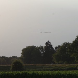
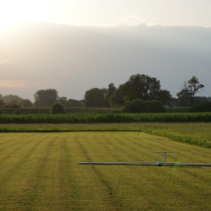
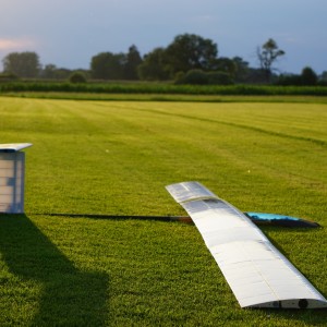
some of you might remember the 28-hour and 81-hour solar-powered flights (the world record in flight endurance for all aircrafts <50kg) by our Pixhawk-powered AtlantikSolar UAV that was presented here at diydrones last year. This year, we have not focused on records, but have been integrating more of our research at ETH Zurich. The result: The first-ever fully-autonomous (including launch, autonomous thermal updraft tracking and landing) solar-powered perpetual flight with significant payload (Color + Thermal Camera + Onboard Computer + WLAN for image live streaming) in a 26-hour Search-and-Rescue (SaR) mission.
One year after having demonstrated the 81-hour continuous solar-powered flight that is still the current world record in flight endurance for all aircrafts < 50kg total mass, the AtlantikSolar UAV has completed its next milestone by demonstrating the first-ever fully-autonomous (from launch to landing) solar-powered perpetual flight with significant payload (Color + Thermal Camera) in a 26-hour Search-and-Rescue (SaR) mission. While the 81-hour and 28-hour endurance record flights were important milestones that demonstrated the perpetual endurance capability of AtlantikSolar, they required manual pilot control for launch and landing and did not carry any aerial imaging payload. However, the missions that our team really cares about – Search-and-Rescue missions relying on long-endurance aerial sensing to support authorities e.g. in the European refugee crisis currently unfolding over the Mediterranean Sea – require both of these elements, i.e. ease-of-use through full launch-to-land aircraft autonomy as well as significant payloads to help the rescue teams with the detection of victims on land and sea.
The 26-hour solar-powered Search-and-Rescue flight performed by AtlantikSolar AS-3 from July 19th – 20th 2016 demonstrated exactly that, and is therefore the first-ever flight world wide to combine:
Perpetual flight: 26-hours of solar-powered day/night- and thus energetically-perpetual flight
Full aircraft autonomy: No pilot stick moved within 26-hours of flight
SaR payload: The aircraft carried a 10 Watt 300g payload (1 Color camera, 1 Thermal Camera, 1 ODROID onboard computer with WLAN) and performed victim detection from the air during day and night.
Environment-aware: The aircraft performed automatic thermal updraft tracking for increased energetic efficiency and to speed up the battery recharge.
Flight summary
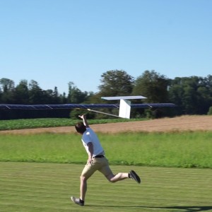
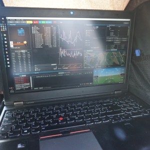
The 26-hour flight was started on July 19th at 18:02 local time in Hinwil, CH with full batteries. The launch was performed fully autonomously: After all system checks were complete, the aircraft was tossed in the air via a hand-launch and then continued automatically and without pilot interaction towards its first loitering waypoint. The respective flight control technology is based on an ETHZ/3DR Pixhawk autopilot with a custom flight controller designed at the Autonomous Systems Lab. Equipped with a color camera, thermal camera, an onboard computer and wireless LAN, the aircraft began live-streaming the respective images. The full payload was operated until around 21 o’clock, after which the color camera was switched off because of the insufficient lighting conditions. The batteries were at 95% state of charge at that time, having started their discharge shortly before 20 o’clock. Note that operating a fully fledged SaR payload consuming 10W is a significant challenge for perpetual flight on a small-scale solar-powered UAV such as AtlantikSolar, and the overall power consumption of ~60W was thus closely tracked during the first hours of the evening flight.
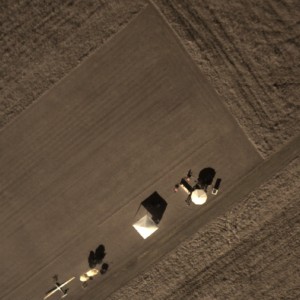
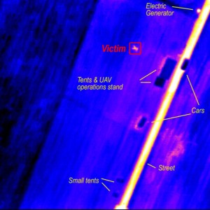
The actual testing of the Search-and-Rescue capabilities were started shortly before 23 o’clock: With the aircraft now flying in total darkness, the infrared camera served as the only source of aerial imaging information. As visible in the video, the payload system clearly manages to find the victim lying in low grass (and surrounding houses, tents, cars, the streets and especially the warm electric generator) at 23:05 o’clock. The victim detection was performed manually by the ground station operator based on the live-streamed images this time. However, the next AtlantikSolar test flight will have automatic on-board victim detection (as already tested in the ICARUS search and rescue project) implemented. The demonstrated capabilities are integral elements of perpetual flight aerial victim detection missions – we are convinced that they can be of great help in solving pressing issues such as the European refugee crisis of 2015 and 2016 above the Mediterranean Sea.
Despite heavy winds of up to 8m/s, the Search-and-Rescue support activities with the infrared camera payload were continued throughout the rest of the night. First sun was hit at 06:20 local time on July 20th, and the minimum battery state of charge was reached with 26% battery energy remaining at 08:04 o’clock. Considering the additional payload power consumption (and mass) of 10W , this energetic margin – achieved on July 20th, and thus about one month after the solar solstice on June 21st – is a success and even exceeds the margin of 23% predicted by our simulations. To accelerate the battery recharging process, the aircraft also implemented autonomous thermal updraft tracking that was enabled during the late morning once thermal updrafts were encountered (see video). Multiple “free” altitude gains of >100m were achieved this way – again without any pilot interaction. The batteries were fully re-charged at 15:30 o’clock.
As a final step, and after 26-hours of solar powered flight, the aircraft performed a fully autonomous landing at the Hinwil, CH airfield. Using its lightweight LIDAR (Light Detection And Ranging) sensor to measure its distance to the ground, AtlantikSolar – a hard to fly aircraft that can usually only be steered and landed by extremely experienced pilots – could safely perform the automatic landing. We consider the demonstrated full flight autonomy a vital step to allow search-and-rescue support teams, which usually do not possess extensive UAV flight training, to benefit from the signficant advantages of solar-powered and in general high-performance UAVs.
Further information
Detailed design and technical information on the UAV platform can be found in “Oettershagen P, Melzer A, Mantel T, Rudin K, Lotz R, Siebenmann D, Leutenegger S, Alexis K, Siegwart R (2015), A Solar-Powered Hand-Launchable UAV for Low-Altitude Multi-Day Continuous Flight. In: IEEE International Conference on Robotics and Automation (ICRA)” [Download] . An additional up-to-date publication including the research for this flight is planned.
Some more impressions from the flight were broadcasted live through our twitter account
T=0h. Autonomous (hand-) launch.
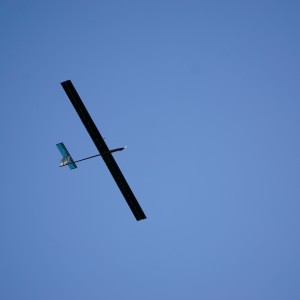
T=2h. Circling above while live-streaming camera data.
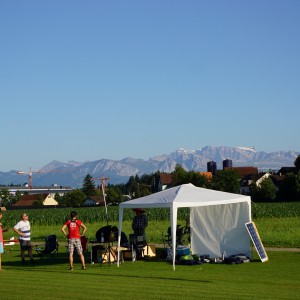
The small operating post in Hinwil, CH.
Live-streamed RGB camera image. Our tents are clearly visible.
T=5h. Flying at night with position indicator LEDs on.
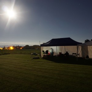
Our tents at night.
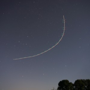
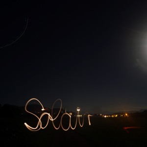
T=5h. The airplane is seen loitering in the top left, performing the SolAIR Search-and-Rescue mission.
T=5h. Live-streamed thermal camera images with annotation. Note the victim that can easily be detected.
T=13h. Ground Station on the next morning. We’ve received first sun here.
T=26h: Final approach during the autonomous landing.
T=26h. Landed autonomously.
AtlantikSolar AS-3 after its 26-hour fully autonomous solar-powered SaR mission.
Acknowledgements
This research was funded through the research project SolAIR – Solar-powered Automated Aerial Imaging and Reconnaissance Using Infrared Cameras. SolAIR is a project funded under Armasuisse contract #043-12. The AtlantikSolar project is in addition funded with ETH Zurich’s internal resources, private supporters, and the European Union FP7 Search-And-Rescue research projects ICARUS and SHERPA . Multiple project partners and collaborators have contributed towards making this important milestone possible, and we’d like to thank all of them for their various and ongoing support. Finally, we are grateful towards the Hinwil and Rafz model aeroplane clubs for providing the airfield!
Pilots: Rainer Lotz, Adrian Eggenberger. Development and Operations Team (Autonomous Systems Lab): Philipp Oettershagen, Rainer Lotz, Amir Melzer, Thomas Mantel, Bartosz Wawrzacz, Konrad Rudin, Thomas Stastny, Timo Hinzmann, Dieter Siebenmann, Dr. Gregory Hitz, Prof. Dr. Roland Siegwart.