All Posts (11086)

Sort by

3689632902?profile=original

We are happy to announce the new version of our Raspberry Pi autopilot - Navio+, that was developed to run APM under Linux. With more than 300 Navios in the wild we’ve got plenty of feedback and now it is time for an upgrade. We have been so busy testing and flying it, that almost forgot to share our latest progress.

For those who never heard of Navio - Navio is a sensor and connectivity shield that allows to run APM’s Linux port directly on Raspberry Pi. Compared to the classic autopilot hardware it is more flexible and provides higher performance for additional tasks as well as for scientific and research purposes. For example, it is possible to perform GPS real-time processing or image recognition.

Full HD video from Raspberry Pi Camera Module can be streamed over long-range Wi-Fi or LTE thanks to the Raspberry Pi’s built-in hardware 1080p H.264 encoder.

To achieve better performance we provide Raspbian image with kernel patched by RT-PREEMPT patch from Ingo Molnar that allows for minimal latencies and real-time scheduling.


3689632856?profile=original

Here’s a list of main features of the new version:

  • New version is compliant with Raspberry Pi’s HAT standard, it fits both on Raspberry Pi Model A+ and Model B+. Our favorite combination is with Raspberry Pi A+, it is very compact and fits on a 250mm copter frame nicely.

  • Power module port for Pixhawk-compatible power modules. Power module provides clean power to Raspberry Pi and sensors from a Li-Po battery as well as current and battery voltage information.  

  • New GNSS receiver - U-blox NEO-M8N, latest generation multi-constellation receiver that supports GPS/Glonass/Beidou and provides better precision and higher update rate.

  • Triple source power supply with ideal diodes - now you can power your Navio+ simultaneously from power module, servo rail and Raspberry Pi’s USB. And if one power supply fails Navio+ simply switches to another.


And other improvements:

  • New MCX antenna connector for solid connection.

  • New RGB LED that looks much smoother.

  • Additional LED indicators.

  • Extended voltage range for PPM input - both 3.3V and 5V are supported.

  • AUX input\output for custom purposes.


Navio has already successfully driven rovers (Himoto Mastadon, Wild Thumper) as well as controlled copters (HobbyKing Spec FPV250 V2) and planes (Multiplex Easystar 2, Hobbyking Bixler 2).


You can get more information about Navio+ on our website - www.emlid.com

Best regards,
Emlid team

P.S. Check out the video of Navio copter fighting with an air flow above the table:


Read more…
Moderator

tusconairspace.png

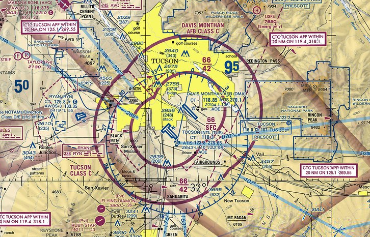
Ok so they have given a 333 exemption to a particular real estate company but you get my drift.

Here's the sUAS News story

This is the money statement.

The FAA’s Decision
In consideration of the foregoing, I find that a grant of exemption is in the public interest. Therefore, pursuant to the authority contained in 49 U.S.C. 106(f), 40113, and 44701, delegated to me by the Administrator, Mr. Douglas Trudeau, Realtor®, of Tierra Antigua Realty, is granted an exemption from 14 CFR 61.113(a) and (b), 91.7(a), 91.119(c), 91.121,91.151(a)(1), 91.405(a), 91.407(a)(1), 91.409(a)(1) and (2), and 91.417(a) and (b) to the extent necessary to allow petitioner to operate an unmanned aircraft systems (UAS) for the purpose of aerial videography/cinematography and augment real estate listing videos. This exemption is subject to the conditions and limitations listed below.

Read more…

3689632680?profile=originalThis camera may be able to improve the quality of shots taken from drones for those jobs where you need the ultimate in precision and texture quality ( I think? ). This is, according to the manufacturer, a camera with smartphone capabilities. It has a Leica Lens, 1" sensor and takes 20MP photos and will go for $1,000 in the US. It weighs 206g, so slightly more than a Canon. I think the benefit is that it doesn't have a zoom lens anymore, so it should be easier to keep the focus.

What remains is to figure out how well the battery lasts and how quickly it can snap pictures and maintain the correct exposure when you fly over land with different reflectivity. This thing having android, I see great opportunities to make it simpler to snap pics, using even for example the 3G connection so you can control it from the ground station. Of course, GPS should be included already.

If you're at CES, give us some feedback on your experiences with the phone when it comes to snapping speeds and exposure compensation :)

Read more…

X-UAV Talon UPGRADES - PART2

3689632739?profile=original

Hi, this is an addition to my prevous blog post.

I consider the rear wing spar a bit "weak" especially when using the wing extenders too. So I modified the wooden parts, I cut off the rear upper parts and replaced by GF ones with bigger (6mm ID) holes. Since the hole size in the foam fuselage is 6 mm originally, a 6mm OD x 4 mm ID carbon pipe can be glued in and the original 4 mm reqar spar can be plugged in. I also replaced the txo joining parts by GF ones.

CAD files and cutting plan can be downloaded from my Grabcad Project page. When doing cuts and glues of the replacement parts, be sure the new part's hole center matches the wooden one!!! Measure things extremely carefully and at least twice!!!

As a comparison, here is the modified and the original solution on rendered images:

3689632739?profile=original3689632803?profile=original


Best regards

Adrian


Read more…

Happy new year diydrones community, I wan't to give you a bit of real-life footage of OpenFPV.

The footage is recorded on the ground station via screen capture to give you a more realistic feeling.

I had not transmissions problems in 15 minutes flight time. Radius about 150 - 300 meters.
The footage is not modified (except cropped).

I started with the lowest resolution and will increase it over time and keep you updated with the results.

The video conversion and yt upload decreased the quality a bit compared to the original footage.

Facts:
- DJI F450 Stock
- 640x480
- 30 FPS
- 160° Lens
- Odroid-W
- FPV Battery lifetime 1h 30min
- 5.8 GHz Wifi

Last post: OpenFPV Update 2 - Roadmap for 2015, Oculus Rift Support, 5GHz

First post: Open Source FPV Project - OpenFPV

Read more…
Developer

Embedded Linux Conference - submit a paper!

3689632392?profile=originalThere are only a few days left to submit a paper for the Embedded Linux Conference in San Jose in March. This is the first conference with a Drone specific track organised under DroneCode.org.

Lorenz Meier and myself will both be presenting at the conference, and it will be a great opportunity for technical discussions within the DroneCode community. I'm really looking forward to meeting other members of the ArduPilot and DroneCode community and hearing about their work.

Call for Papers

The CE Workgroup of the Linux Foundation would like to invite you to make a presentation at our upcoming Embedded Linux Conference.  The conference will be held March 23 - 25 in San Jose, California.  The theme for this year is "Drones, Things and Automobiles", and we're excited to discuss some new areas where embedded Linux is really taking
off! (pun intended)


For general information about the conference, See http://events.linuxfoundation.org/events/embedded-linux-conference/

For information about the call for participation, see http://events.linuxfoundation.org/events/embedded-linux-conference/cfp

Please note the guidelines on the CFP page.  It's usually pretty obvious when we're reviewing the abstracts, as a program committee, who has read the guidelines and who hasn't.

ELC is the premier vendor-neutral technical conference for embedded Linux developers. The conference is open to the public.

Guidelines

Presentations should be of a technical nature, covering topics related to use of Linux in embedded systems.  Topics related to consumer electronics are particularly encouraged, but any proposals about Linux that are of general relevance to most embedded developers are welcome.

Presentations that are commercial advertisements or sales pitches are not appropriate for this conference.

Especially encouraged this year are talks in the following areas:

  • Linux in Automotive
  • Drones and Robots
  • Linux in the Internet of Things


And we'd also love to hear your proposals in the following topic areas as well:

  • Audio, Video, Streaming Media, and Graphics
  • Security
  • System size, Boot speed, and Real-Time Performance
  • Flash Memory Devices and Filesystems
  • Build Systems, Embedded Distributions, and Development tools
  • Mobile Phones, DVRs, TVs, Cameras, etc.
  • Practical Experiences and War Stories
  • Standards


Most presentation slots will be 50 minutes long, including time for questions.

Tutorials, demos, and Birds-of-a-Feather sessions may also be proposed.

The deadline for submissions is midnight January 9, 2015 PDT.

To repeat, for additional info and details for making a proposal, see http://events.linuxfoundation.org/events/embedded-linux-conference/cfp

Read more…
3D Robotics

OpenDroneMap adds image processing

3689632439?profile=original

Via Christian Ledermann:

OpenDroneMap, which previously would just create point clouds from drone images, now also produces:

* Meshes!
* Textured meshes!
* Georeferenced textured meshes
* Georeferenced orthophotos!

More from PublicLab:

What I want to do 

OpenDroneMap (http://opendronemap.github.io/odm/) is a tool to postprocess small Unmanned Aerial Vehicle (sUAS), balloon, kite, and street view data to geographic data. With the current update, we are adding the ability to create orthophotos from drone, balloon, and kite imagery which has GPS ephemeris. Future versions will permit the use of GCPs with no onboard GPS.

My attempt and results 

Good news to report, though I haven’t finished my own testing yet… but OpenDroneMap, which previously would just create point clouds from drone images, now also produces:

  • Meshes!
  • Textured meshes!
  • Georeferenced textured meshes (if the exif data has geographic coordinates)
  • Georeferenced orthophotos! (if the exif data has geographic coordinates)

Now, I’d like those ifs to go away, but that requires a bit of thoughtful interface work. In the mean time, give it a whirl on your data.

Work left to do:

  • Refine processing chain
  • Allow for input of GCPs for images without GPS in their exif
  • Blending / brightness correction, etc. of input images
  • Digital surface model output

See this branch on github for the whole package : https://github.com/OpenDroneMap/OpenDroneMap/tree/texturing_orthophoto_spotscale_additions.

seneca_screen.jpg

odm_orthphoto.png

Conclusions 

There's still plenty of work to do to bring this to really low tech use cases, but this project now has a good skeleton to build toward that outcome.

Read more…
3D Robotics

Qualcomm getting serious about drones

Qualcomm is a member of the Dronecode Foundation and has ported the APM code to the Snapdragon platform. Now, at CES, they're showing the first glimpse of their work:

Qualcomm Research is building the core technologies to enable both rolling and flying autonomous robots. We are demonstrating our state-of-the-art computing platform, built around the Qualcomm Snapdragon processor, with the Cargo. This drone can roll, fly, and perform vision-based obstacle detection in 3D space. See it for yourself this year at CES 2015! Qualcomm Booth: LVCC Central Hall, #8252 www.qualcomm.com/ces

Thanks to Lorenz Meier for the link!

Read more…

Sailing to Hawaii Continued

3689632183?profile=original

A lot of people have contacted me for more pics, so I thought I would throw up some more. I will give some minimal content with them. If you have any questions, fire away and I will answer in the comments.

The first iteration of controller and Pixhawk. At the time I thought The Pi would be too big and draw too much power. Power was ok, but definitely too big.

3689632211?profile=original

When I got the hull from Radtek, I originally planned to use three 50 watt solar panels since I could not find a 150 watt panel that was narrow enough to fit on top. The width of the hull is 21". The length is 92"

3689632141?profile=original

I also planned to use the push pull system for the rudder. I quickly found out that even a heavy duty servo could not tolerate a week pushing water back and forth in my torture test bucket.

This caused me to rethink and redesign the rudder system. I eventually went with a thru-hull rudder system. This is a typical powerboat brass rudder port mounted on top of a 1/4" carbon fiber plate. On the bottom of the hull is a 1/4" ABS plastic plate. With weight ever increasing, I went with a kayak rudder and an 1" diameter aluminum rudder shaft.

3689632258?profile=original

After weeks breadboarding everything and testing, the final control system looked something like this. As you can see from the picture I moved from the servo rudder control to a linear servo. This one has 135 lbs of thrust and handled the bucket challenge with no problems.

3689632230?profile=original


3689632275?profile=original

The servo installed in the hull. I was very fortunate that the servo lined up almost perfectly with the rudder aperture. This is the only pic I could find of the servo so the candy obscures part of it.

3689632250?profile=original

Once all the systems were figured out, the challenge became how to fit them into a small enough water tight container. This caused a lot of grief.  This is a first attempt.

3689632199?profile=original

Finally I found the perfect waterproof container for the electronics

3689632299?profile=original

At the back are the waterproof ports for most of the electronics. The exposed sma connector attaches to the Satellite antenna. In all I drilled about 15 holes in the case for cabling.


3689632368?profile=originalExpecting that the ocean will batter the crap out of this, I mounted a carbon fiber plate to the the hull and bolted the electronics to the hull via vibration mounts. These mounts will keep the electronics about an inch off the hull. Hopefully the vibration will be significantly reduced.

3689632410?profile=original

Juggling family and a full time job meant that everything was done from 8pm till the wee hours of the morning, hence this taking a year (and counting). Soldering success at 3am. I had blown through 4 boards before this one by letting the solder touch and failing to clear it properly before plugging the controller board into a power source. 

3689632312?profile=original

I went with a 100AH battery after figuring in the power requirements. Just running the electronics 24/7 added up quickly not to mention powering the motor and the rudder. Since this platform is designed to drift with the current and monitor the ocean/air once it reaches a certain point, there will not be a constant high load demand on the battery. Getting to its destination is another power story entirely. lol...

I wanted to be able to stay on-station for many days even in the event of a lack of sunshine. A 100ah LIFePO4 battery weighs about 26lbs. You can see the battery installed in the hull in my previous post.

3689632427?profile=original

Once the battery was in, I then had to wire up to the charge controller and also wire up a secondary chrage port so the battery could stay charged while inside. At one point I had wires coming out of all parts of the boat. The usb ports for talking to the pixhawk and other devices are in the shot as well

That's all for now. If you have any questions, let me know.

I should have some more photos up at 

http://twitter.com/pacificbots

Read more…
3D Robotics

3689632072?profile=originalGreg has already mentioned the new APM-powered Walkera H6, shown above, which they'll be showing at CES. But one other thing I wanted to highlight is that how well they're working with the open source community on this and their other products. As they proudly note in their press release:

Walkera is a founding member of the Dronecode Team, an open source, collaborative projects that brings together existing and future open source drone projects under a nonprofit structure governed by The Linux Foundation.

Other APM-powered copters in the Walkera line include the Tali 500:

3689632095?profile=originalAnd the Scout X4, which I have an like a lot:

3689632120?profile=original

Read more…

Walkera is the first "inspired" company?

3689632046?profile=original

When I first saw Dji Inspire, i was really impressed, I'm sure, just like the rest of you guys. It's really something new, with cool and smart design, really inspiring. The Dji's design is a separate subject, it's something worth analysing.

But today i wanted to turn your attention to something less technical. Im thinking about the name of the drone - "Inspire".

After the exciting hours of first impressions of Inspire, trying to catch the details of the design, features, parameters, i realised that the name "Inspire" will in fact inspire a lot of companies to copy the design. The name is almost like an invitation to coping it. 

So we didn't have to wait long to see inspired designs. Walkera is showing their APM-powered H6 at CES 2015, which looks a lot like Dji newest drone. 

www.youtube.com/embed/DPufN3Pk3Dc

As we know, Dji patented moving arms, so they could also be used as landing gear. So Walkera made unmovable arms, and retractable landing gear fixed to the centre plate. But the rest is very similar.

3689631997?profile=original

The rest is unknown, but if the price is right, i mean more reasonable than Dji Inspire, and APM is controlling the drone it may be some alternative. 

So it appears that people want cool looking drones. Will we see a burst of original designs? Is 3DR building their own "Inspired" drone? Hopefully! :) 

Read more…

Using Andruav as 3G/4G Telemetry for APM ArduPilot


This is my third article about Andruav, last one was a couple of weeks ago that was about the Telemetry feature in Andruav.

Since then some updates has been done to telemetry that I want to mention it here.

Andruav Telemetry has taken one more step forward. Now it can use USB besides Bluetooth when connecting to Flight Control Board (FCB). Also communication between drone and GCS has been extended so that  Andruav GCS can detect multiple telemetries on different drones and switch between them as shown in above video. Also protocol overhead has been reduced, which allows it now to work with less bandwidth up to 25%.

The video shows the below setup configuration:

3689631979?profile=original

We have two Andruav mobiles, one of them on Quad which is the  Drone-Mode Andruav and the other on land in pilot's hand which is GCS-Mode Andruav , The Quad has  Ardupilot board, the board is connected to Drone-Mode Andruav using USB cable - it can also use a Bluetooth connection-. 

On ground we have GCS-Mode Andruav mobile, and another mobile that runs Droid Planner, BTW you may use a laptop with Mission Planner on it.

The video starts actually showing when everything is connected and then make a playback showing from the beginning how to make such connection.

I want here to mention three things:

1- My english language is bad :( sorry .... I need to work on it.

2- When trying to make this type of connection you need Andruav GCS to have access to both a wi-fi and Internet, so you have two options:

     a. Andruav GCS is connected to a wi-fi that can access Internet as well.

     b. Andruav GCS has 3G/4G connection, and here you need to enable Wi-Fi Tethering so that the third mobile can connect to Andruav GCS. 

     In my demo all mobiles where connected to Wi-Fi router, however both Andruav  mobiles are connected and communicated through a server in Andruav.com server.

 3- If you see the last part of the video you will find that Andruav Camera Shooting and HUD info are working and independent of the telemetry feature that works in parallel.

Have a safe flight :)

Read more…

New Payload for mini UAVs

NEW Gimbal

CM100CM100phoca_thumb_l_cm100-top-view-294x300.jpg

Gimbal Capabilities

  • Size (DxH): 100mm x 129mm or 3.9in x 5.0in
  • Weight: 695g or 1.5lb
  • Power: 12W
  • Position Accuracy: 0.022° or 380µrad
  • Elevation: ±115°
  • Azimuth: 360° Continuous
  • Slew Rate: 105°/s or 1.83rad/s

Video Output

  • Analogue Output: Composite
  • Digital Output: .h264 up to 10Mbps
  • Snapshots: HD (Stored on Board)
  • Streaming: EO 720 x 576 and IR 640 x 480

CM100

The Latest Gyro-Stabilized Multi-Sensor


  • Dual Sensor - EO and IR in the Same Unit
  • No ITAR or Export Restrictions
  • Low Size, Weight, Power and Cost
  • IP63 Rating

https://www.youtube.com/watch?v=cLOWcIBBIk8

https://www.youtube.com/watch?v=28nVA8CmKPA

https://www.youtube.com/watch?v=0dGx8cUsM4c

https://www.youtube.com/watch?v=fmTeAcFahfQ

https://www.youtube.com/user/uavvision

Read more…

X-UAV Talon UPGRADES

3689631876?profile=originalHi, today I decided to share all my upgrades I designed and built for my Talon.
Since attachable picture number is limited here, detailed photos and more renderings can be fount on the project GrabCAD page, together with the neccessary .STL files and .DXF files for parts. These upgrades doesn't need difficult modifications on the Talon fuselage, all of them fits to the foam parts.

Please don't forget, if you like my work, you can donate me with some bucks!!! ***THANKS IN ADVANCE***


1) GimBALL adaptation for talon.

  • you will need 2 mm GF (aka. glass fiber sheet like G10) plates,
  • some 3D printed parts
  • 4 pieces of 10 mm long M3 rubber shock absorbers (the length is important to be 10 mm, if you have smaller blocks, use some spacers),
  • on pitch: HK-2206-140KV,
  • on roll: RCTimer 2212,
  • you have to buy a big sized motor mount cross or make one from aluminium or GF plate

2) Langing gear

  • This is a reinforcement for the fuselage to stable, rigid landing gear solution. You will need 2 mm GF sheets,
  • 5 pcs of MPJet Mounting Nuts (MPJ1005 code)

3) Camera mount

  • This is a roll-stabilized camera mount I designed for my Canon IXUS 100 camera. You will need 1,5 mm and 2 mm GF sheets,
  • a 3D printed camera lock
  • 5-6 mm thick silicon foam for shock absorbing
  • 2 pcs of d5xD11xw5 flanged bearing
  • a Turnigy TGY-306 (or same sized) servo
  • some screws, linkage rod, linkage ball

4) Misc. parts

  • I designed a small 3D printed pitot tube holder for the original 3DR pitot tube. The two parts needs to be glued together.
  • Also I replaced the wooden tail skid to a 2 mm GF part, for longer life.

I hope you enjoy them, I wish you happy and successful building!

*** CAUTION - 1*** Please note that I spent on many hours on designing and building them, regarding my current needs. I won't modify any of them for further requests (ie. other type of camera) unless you pay my efforts, since I'm doing this in my limited spare time. Thanks for understanding...!

*** CAUTION - 2***  Please note that I designed all 3D printed parts to be printable on a Stratasys FDM printer, which uses support material system too. I didn't tested the printability on a cheaper DIY printer family without support material, maybe parts can be printed on them too, maybe not... ***

Best regards

Adrian

3689631778?profile=original 3689631676?profile=original

3689631898?profile=original3689631834?profile=original

Read more…

DIY Ghetto Retractable Landing Gear

3689631853?profile=original

Hello and happy new year.

I decided that I wanted to have retractable landing gear on my hexacopter, but I didn't want to pay the full price for a ready made set (£50/$80). With all the parts I gathered, it came to about £12/$18, so that's quite a saving to be made.

I made a write up article to help others to make their own in hope that we can begin to develop the Ardupilot to enable automatic retracting landing gear like on the DJI systems A2 flight controller. I hope that Droidplanner will have a dedicated button to enable/disable auto landing gear, and also to set the altitude trigger, using either the barometer or gps or optical flow sensors. If anyone has undertaken this suggestion already, i'd be grateful for some links posted in the comments. 

Many thanks and happy flying

Tutorial Link: http://dalybulge.blogspot.co.uk/

Read more…
3D Robotics

3689631639?profile=original

Via BoingBoing, a heart-warming story (and not just because it was all APM!): 

The folks at Digital Democracy worked with the Wapichana people in Guyana to build a drone, demonstrating that indigenous people could build and use the devices to monitor illegal deforestation and inform resource management. "We Built A Drone"

We Built a Drone from Digital Democracy on Vimeo.

Can drones be a tool for positive change in the hands of indigenous communities? Can communities use them to create maps and monitor illegal logging and deforestation? To answer these questions I travelled to Guyana in October and together with the local Wapichana monitoring team we built a drone and made a map. Watch the video to find out how we did.

Drones, or “Unmanned Aerial Vehicles” (UAVs) have a bad reputation, andrightly so. But they are no longer just tools of the military; the cilivian drone market is rapidly growing, with applications from film-making to precision agriculture to mining. Anybody can now buy a quadrocopter online that you can fly with your cellphone for under $500.

This technology has huge potential for humanitarian and conservation goals: Drones can rapidly create high-resolution up-to-date imagery at a fraction of the cost of satellite imagery. In Guyana we are working with the Wapichana people to help them monitor a vast territory of 7 million acres of savannah and rainforest. We saw the potential for drones to monitor and map deforestation, from mapping the changing size of bush islands on the savannah to catching illegal logging deep in the forest.

We didn’t want to just fly into Guyana and fly a drone over the local villages. Our interest was whether this technology could be something that can be used and controlled by the communities themselves, and become a tool of empowerment for helping them have more of a say in their own future. We wanted the Wapichana to be able to repair it themselves, fly it themselves, and process the images to use for their own means.

Building a Drone Together

Tessa soldering a drone

I arrived in Guyana with a bag of foam, wires, glue and tools. The Wapichana monitoring team arrived, five men and one woman from villages throughout Wapichana territory. We worked under the leaf roof of the “benab” – the community house – and together learnt how to build a drone, from ironing laminate to strengthen the wings to soldering a live video transmission system.

I was amazed at how quickly the team learned, and their initiative at solving engineering problems with the limited tools we had available. When the motor mount broke, the team scoured the village for different types of plastic, and fashioned a new mount from an old beer crate. The drone was no longer a foreign, mysterious piece of technology, but something they owned, built, and therefore understood.

Flight testing

We chose a fixed-wing drone for Guyana. A quadrocopter is much easier to fly, but it has limited range and is much harder to fix when it breaks. But flying a plane is hard, and landing is harder. We connected the remote control to a flight simulator and the team stayed up late into the night practicing flying and learning the controls.

We built two drones. The first was not strictly a drone since it had no autopilot, and was really just a remote control plane. This was our practice plane, for learning how to put it together and learning to fly. And just as well: as you can see from thevideo above our first flights did not go well.

Our second drone was much more complex and fragile, filled with cameras and an autopilot. The practice paid off and it took off smoothly on its first launch. The autopilot made it much easier to fly, and from the live video feed we could watch the “drone-eye-view” as we flew. We also had a wireless data-link with the autopilot, with a tablet and laptop showing a live flight path, airspeed, altitude, and remaining battery.

Making a Map

To make a map with a drone you need to fly a fixed flight path back and forth in strips across the area you want to map, taking multiple overlapping photographs. We used open-source mission control software called Mission Planner to create flightplans and monitor the flight in progress. We also tested similar software for a tablet. We mounted aGoPro (generously donated by GoPro) into the drone and set the shutter to take a photo every two seconds.

The entire process was automated: We pulled back the drone on our home-made bungee launcher, and flicked on the autopilot. The motor spun up, we crossed our fingers, and let go. We watched nervously as it gained altitude, our eyes on the live video and flight path as it flew back and forth over the village. Incredibly, it worked! After 20 minutes it finished its flightpath and came back and flew in circles overhead, waiting for us to bring it in to land manually.

The GoPro shot about 500 images, which we processed usingPix4Dmapper. This incredible software builds a 3D model just from the images, using image analysis to detect features and calculate camera angles. The full version costs $8,700 but the free version is fully functional but only exports video. Processing took about 6 hours on a fast laptop, but was a point-and-click process that will be easy for the local mapping team to complete. The resulting 3D model of Sholinab village is spectacular:

Next Steps

The Wapichana monitoring team have shown that a remote indigenous community with no prior engineering experience can build and fly a complex drone and make a detailed map. Our next step is to continue training to get the whole team comfortable with flying and to streamline the process from mission planning to processing imagery. Ultimately we want this to be a tool that the monitoring team can deploy at the request of the Wapichana villages. So far we’ve discussed using it to monitor deforestation of bush islands over time; creating high-resolution maps of villages to use as a basis for resource-management discussions; and flying over logging camps in the forest to document illegal deforestation.

I’ll be following up with more technical posts sharing our learning around the different components and technology, with a hope that other organizations and communities around the world can build on and learn from our experience. We wouldn’t have been able to do this without others sharing their experience, in particular Lian Pin Koh fromConservation Drones, the community at DIY Drones, and Trent fromMyGeekShow, who spent hours on Skype patiently explaining everything from battery technology to the best material for a launcher bungee.

Drones are just one technology we are exploring that allow indigenous communities in some of the most fragile and biodiverse ecosystems on the planet to monitor their territory and speak out against deforestation, oil drilling and mining that threatens their way of life. We are building smartphone apps for documenting oil spills on the ground; web apps for analyzing satellite imagery; simple tools for making maps offline; and interactive online maps for reaching an audience around the globe.

If you like what we are doing then please consider making a donationto support our work or donate your time and join our Rainforest Hackathon in February.

Read more…

3689631676?profile=originalHi,

I continue my blog with the integration of GimBALL into the nose of an X-UAV Talon.
Because of complexity and available space in the Talon's nose, I decided to build it with 2-axis stabilized setup.

I hope I'll be able to test it in the air soon, and will share some test videos. Till then, here are some sample images about the current state:

3689631624?profile=original 3689631713?profile=original

3689631701?profile=original

Regarding STL files, finally I decided to share them at GrabCad.
If you like my work, you can donate me with some bucks too!!!

Please note that this is an experimental work, and maybe need some modifications, adjustments to successful operation. Use my files on your own risk!!!

Here are the suggested motor types again:

  • on pitch: HK-2206-140KV
  • on roll: RCTimer 2212
  • regarding yaw, my first thought was RCTimer 2804 hollow shaft, but initial testing shows that it is not strong enough. So I made a modified arm with flat top too (rev2 files), so much more big motors can also be used

Please note also that I'll not modify GimBALL for any other cameras than MobiusHD because design process needs a lot of time and I'm doing DIY things in my limited spare time. Sorry HERO users. Please do not ask me, I'll not reply to these. Thanks for understanding!

Next time I'll show you some sample videos! (PART3). Stay tuned!!!


Read more…
3D Robotics

3689631662?profile=originalFrom Linuxgizmos:

Gumstix announced a gen-2 micro-areal vehicle (MAV) controller based on its tiny gumstick-sized Overo COMs, and customizable via a free online design tool.

The AeroCore 2 is an update to the original AeroCore controllerintroduced last Spring. Like some other hacker-oriented UAV autopilots, such as the Erie autopilot, both of Gumstix’s AeroCore models run Nuttx RTOS for real-time control tasks, along with Linux for higher level functions.


gumstix_aerocore2_angle-sm.jpg
AeroCore 2 baseboard with unpopulated Gumstix COM socket
(click image to enlarge)


The AeroCore 2’s real-time-task-oriented microcontroller is an ST Microelectronics STM32F427 MCU, based on a single ARM Cortex-A7 core clocked at 180MHz. As in the case of the original AeroCore, the AeroCore 2’s MCU supports low-level machine controls and sensors, while high-level Linux programs running on a piggybacked Gumstix Overo COM manages mission intelligence, including visuals.


gumstix_aerocore2_front-sm.jpg gumstix_aerocore2_back-sm.jpg
AeroCore 2 baseboard front (left) and rear
(click images to enlarge)


Gumstix says its AeroCore MAV controllers support integration with open-source projects like Robot Operating System (ROS), APM-based PX4, and PX4-compatible projects such as QGroundControl and MAVLink. This software ecosystem is said to enable the incorporation of firmware like optical-flow analysis program and target acquisition algorithms.

In contrast to the original AeroCore, which uses the company’s dual-core, ARM Cortex-A9-based “DuoVero” COMs ($170-$200), the AeroCore 2 pairs with the lower-cost, ARM Cortex-A8-based “Overo” COMs ($99-$179), based on ARM Cortex-A8 processors. The new board obtains its GPS functionality from a GPS module that plugs into an industry-standard connector, “thus enhancing functional modularity and choice while reducing cost,” says Gumstix.

Other than mentioning that the AeroCore 2 MAV controller includes CAM, Spektrum RC, and GPS interfaces, neither the the company’s press release nor the AeroCore 2 product pagecurrently offer detailed specifications, block diagrams, or other documentation. However, The original AeroCore MAV controller provides multiple control options for up to eight motors, and integrates a 6-axis accelerometer with magnetometer, as well as a 3-axis gyroscope and barometer. Additionally, various expansion headers offer interfaces such as SPI, I2C, UART, and GPIO.

 
Gumstix Overo COMs

Gumstix now provides 14 versions of the Overo COM series, based on different versions of TI’s OMAP35x family, as well as on enhancements like wireless modules and extended temperature support. Overo models, such as Sand, Fire, Tide, and Water, are also offered in memory- or processor-enhanced versions with the STORM suffix.


gumstix-overo-tidalstorm-sm.jpg
Overo TidalSTORM COM, front and back
(click image to enlarge)


Gumstix has long supported its Overo COMs with Yocto Linux.

 
Designed, and customizable, with Geppetto 2.0

Gumstix announced the AeroCore 2 in conjunction with the public unveiling of version 2.0 of its web-based “Geppetto” design tool, with which it designed the board. Because AeroCore 2’s design was implemented using Geppetto, developers can quickly and easily modify it to satisfy custom requirements, says the company.


gumstix-geppetto-design-example-250.jpg gumstix-alto35-geppetto-model-250.jpg
Typical Geppetto design models


Once the Geppetto-based modifications are complete and pass the tool’s verification tests, prototypes can be ordered for a setup fee of $1,999, plus component costs, for delivery in approximately 15 business days (average for “verified designs”), says Gumstix. In addition to providing a simple, web-based board design and modification process, Geppetto 2.0 is said to offer crowd-funding features that let a community of developers collaborate on a board’s design or modification, and then share in funding its prototype builds.

“Anyone from electrical engineers and industrial designers to educators and hobbyists can create devices with Geppetto’s intuitive drag and drop approach to connect USB plugs, network connectors, LEDs, or even whole computer-on-modules to meet custom specifications without the cost of conventional electrical engineering, layout and manufacturing,” states the Gumstix Geppetto page.

 
Gumstix MAV legacy

gridswarm_ultraswarm.jpg
UltraSwarm

The AeroCore 2 controller is the latest in a decade of Gumstix support for micro-helicopter projects. TheUltraSwarm helicopter, demonstrated by the University of Essex ‘s Gridswarm project in 2005, ran on an early Gumstix module that was powered by an ARM-based Intel PXA255 XScale processor running at 200MHz or 400MHz.

 
Further information

The AeroCore 2 sells for $149, which does not include the cost of the user’s desired Overo COM. Sales and technical information may be found at the AeroCore 2 product page and in the AeroCore 2 and Geppetto 2.0 press release. Pricing and technical information regarding the AeroCore 2-compatible COMs are available on Gumstix’s Overo COMs product page. 

Read more…

3689631605?profile=original

The end result has turned into a research platform that is intend to be used as a self-positioning buoy to monitor the ocean environment. The buoy will move to a specific area of the ocean and then drift with the current while monitoring takes place from the on-board instrumentation packages.

What will be monitored:

  • Weather (air temp, pressure, apparent wind speed and direction)
  • Ocean Salinity, PH and Temp.

The platform will be powered by a 100AH LIFePO4 battery charged by a solar array.

Follow me on http://twitter.com/pacificbots for more pics and updates!

Read more…