All Posts (11086)

Sort by

(Montreal, Canada) November 17, 2014

Eighteen teams of young engineers-in-training competed for the right to call themselves world champion drone builders at the 22nd annual ASME Student Design Competition (SDC) finals today at the International Mechanical Engineering Congress & Exhibition at Montreal's Palais des Congrès.

The international slate of teams – including squads from universities in China, France, India, Peru, Turkey and across the United States – brought their talent and training to bear on one of today's hottest mechanical technologies: Unmanned Aerial Vehicles (UAVs) or as they are better known, drones. Each team had designed and built a powerful, maneuverable, remotely-piloted drone to fly in this year's competition.

Today, drones are one of the world's hottest technologies. Though an industry still in its infancy, drones and their potential have captured the imaginations of leaders in business, government and academia. They promise new solutions for difficult, dangerous or time-critical tasks in industries from agriculture to emergency medicine, from energy to journalism and beyond.

The SDC Challenge for 2014: design and build an original drone, pilot it successfully through a series of high and low obstacles, complete a targeted payload drop, and return to the start -- in one piece.

Student engineer Oscar Wall Arias of the Instituto Tecnológico de Ciudad Juarez (Mexico) exemplified not only the technical excellence of the assembled teams but their humane ambition. "We're engineers," Arias said. "We're here to do good, to build, to make human lives better. What a great thing to be here with all these great teams today."

At day's end, the University of North Dakota team took first place with their massive 78.4lb. gleaming steel-and-aluminum machine. Second place went to the nine-man, black-clad squad from California Polytechnic State University. Third place was taken by the "Airwolf," the drone flown by the "Wolfpack" team from North Carolina State University.

Every year, the SDC tests the mettle of young engineering students through a design-and-build challenge based on latest developments in industry and academia. A committee of ASME members led by Dr. Tim Hodges, Professor of Mechanical Engineering at the Virginia Military Institute, works throughout the year to bring the SDC to life.

"Students get to use their engineering knowledge to design and build a vehicle, and then they get to compare their work with that of their peers," Hodges said. "It gives them lots of confidence to work into the future and toward employment in the real world. And they have done such a wonderful job." Wearing protective glasses and clutching clipboards, Hodges and his colleagues also served as judges of the competition.

And a great day of competition it was: motors roared; assembled crowds hooted, laughed, and cheered; multicolored, multi-propellered flying robots swooped and zoomed high, loud and sometimes dangerously close to the competitors and judges in the arena. Judges' papers were repeatedly blown away by the windy force of the machines in flight. And though many succeeded, several entries crashed and shattered, with carbon-fiber blades and aluminum struts flying in all directions.

ASME President J. Robert Sims was deeply impressed by what he saw. "From looking at the exhibits and talking to the students, their dedication and expertise is just amazing," Sims said. "These folks are going to do well in the future in engineering. It's just a very impressive group – all of them. Whether they're winners or not in the finals, they are incredible individuals."

Said Scott McDaniel of North Dakota's winning team: "We drove two full days to get here from North Dakota – I'm so glad we did!"

For more information about SDC 2014 or the American Society of Mechanical Engineers, please contact: Deborah Wetzel, wetzeld@asme.org , 917-580-0974, or Roger Torda, tordar@asme.org, 917-456-6882.

##

Provided by the American Society of Mechanical Engineers (ASME)

Full Roster of Teams in ASME 2014 Student Design Competition

North Carolina State University (Raleigh, NC)

Wentworth IT (Boston, MA)

New York Institute of Technology (New York, NY)

University of North Dakota (Grand Forks, ND)

University of St. Thomas (Saint Paul, MN)

University of Arkansas at Little Rock (Little Rock, AR)

Texas Tech University (Lubbock, TX)

California Polytechnic State University (San Luis Obispo, CA)

University of the Pacific (Stockton, CA)

Germanna Community College (Fredericksburg, VA)

Baker College (Flint, MI)

Instituto Tecnológico de Ciudad Juárez (Chihuahua, Mexico)

BITS Pilani (Dubai, UAE)

University of Engineering & Technology Lahore (Lahore, Pakistan)

Universidad Nacional de Ingenieria (Lima, Peru)

Yeditepe University (Istanbul, Turkey)

Hong Kong Polytechnic University (Hung Hom, Kowloon, Hong Kong)

Prince Mohammad bin Fahd University (Al Khobar, Saudi Arabia)

SRM University (Tamil Nadu, India)

ISAE Supaero (Institut Supérieur de l'Aéronautique et de l'Espace - Toulouse, France)

National Tsing Hua University (Hsinchu, Taiwan)

Read more…

Defiance Airframe development

R3mECh.jpg

6SktaN.jpgLatest update on things: DefianceDevelopementThread

MkxjBY.jpg

Hi guyz, its been a while since i reported back about my enthusiastic project, 'In search of design functionallity'.

Time has come to show you what i've been working on for long time, i'm very excited, the jurny was long and dreadful but every second of it was worth it.

Main design goal;

- compact and functional design

- protection of all electronics by the airframe body while keeping them accessible(armor tanked)

- usage ergonomy, easy to maintain (wiring and electronics)

- optimal electronic placement, to achive healty working enviroment for all components by keeping them away from eachother to prevent mutual EMI. (flight control, videio transciever, radio reciever, power distribution, esc, both vtx and rx anntennas, camera)

- stable and lock in flight characteristics (achived with central COG on all axles by symetric motor placement and centered component placement on vertical axis)

- an airframe that provides easily achivable clean build 

-great battery fitting capacity

- fully optimized for both 5 and 6 inch propellers, 3 and 4s powersystems

- great orientation propertys, serve as both, an LOS skill training model and full blown fpv beast, also easy to spot for the spotter and in fpv racing

- frame profile designed to take a beating, able to translate direct frontal crash at 25degree into rotational force to dissipate impact energy and incrise model longevity

- sensible engineering, usage of right materials in all the right places, g10 where RF transperancy is desired and true 3k carbon fiber only where its needed.

- light weight

- high quality

- fair pricing, affordable

- available

Few renders of an actual assembly model 

oYZGTi.jpg

lybFum.jpg

7G8Kbp.jpg

Here is the latest screenshoot from actual model assembly file

f3o9Ca.jpg

I'm looking foward to your thoughts and suggestion 

You can also follow up my thread about it on fpvlab, but i'm more than happy to answer all Q&A here too.

Defiance thread

Update:

New feature - adaptable motor protection

A few people suggested some form of motor protection so i designed an adaptable motor protection giving the pilot a choice of motor protection 'level' he feels most comfortable with.

Arms have 'teeths' providing great distancing of motor bell from the edge of an arm, however it is possible to install protective rings wich give additional protection along motor vertical axis. The same mount holes can be used to install landing gear as well.

While obvious that teeths are most effective during crashes on solid ground, the protective rings make it more secure for most ground types.

Enough talk, few screenshoots :)

fs5DK3.jpg

tWJ0FF.jpg

OxHsxf.jpg

As always, looking foward to feedback:)

This is the final design assembly file screenshoot, features few construction updates that provides great ease of us, maintainance and structural reinforcement for 6incher powersystems.

More about those updates at: Defiance Thread

zeZDxw.jpgNew update on things, I've posted first Defiance prototype build photos, heres a link BuildPhotos.

attachment.php?attachmentid=55303&d=1417381498

Read more…

3689626270?profile=original

Link:

Drone Flights Illegal.

Excerpt from above article:

Some very bad news for drone pilots this morning: An appeals board has ruled that the Federal Aviation Administration has wide latitude to make all drone flights illegal in the United States.

​The decision, by the National Transportation Safety Board, determined that the FAA's existing "aircraft" regulations can apply to model aircraft, drones, and remote controlled aircraft, which is perhaps the most restrictive possible outcome for drone pilots in a legal saga that has dragged on for more than a year.

Read more…
3D Robotics

Gobot -- Drones programmed in the Go language

3689626416?profile=original

GoBot is a new robot-control applications interface using the Go programming language, including support for 3DR copters and others using MAVLink.

Platform Support

Gobot has a extensible system for connecting to hardware devices. The following robotics and physical computing platforms are currently supported:

15 Platforms

Read more…
3D Robotics

Angela Merkel admires an IRIS

3689626317?profile=originalOne of our great academic collaborators, Fabio Ramos at the Australian Centre for Field Robotics, uses both Iris and Aero as a research platforms. German Chancellor Angela Merkel visited the center this week,
Fabio also works for NICTA (that's the sign in the background), which is basically the Aussie version of NSF.  They are led by the very famous roboticist Hugh Durrant-White, who did the original work on SLAM.  
3689626403?profile=original
Read more…

3DR Robotics group flight

Here is 3D Robotics centric group flight. Iris+ and his grandpa 3DR Quad on a mission. Playing around with scenario to cover large area with multiple vehicles simultaneously. Can be handy for Search&Rescue, surveyors and others.

Additionally you can see a proximity warnings in UgCS in action. These can use ADS-B as a source as well.

Thanks!

UgCS Team

Read more…

2014 ASME Student Design Competition finishes

3689626366?profile=original

(Excerpt below is from this press release)

"(Montreal, Canada) November 17, 2014

Eighteen teams of young engineers-in-training competed for the right to call themselves world champion drone builders at the 22nd annual ASME Student Design Competition (SDC) finals today at the International Mechanical Engineering Congress & Exhibition at Montreal's Palais des Congrès.

The international slate of teams – including squads from universities in China, France, India, Peru, Turkey and across the United States – brought their talent and training to bear on one of today's hottest mechanical technologies: Unmanned Aerial Vehicles (UAVs) or as they are better known, drones. Each team had designed and built a powerful, maneuverable, remotely-piloted drone to fly in this year's competition.

Today, drones are one of the world's hottest technologies. Though an industry still in its infancy, drones and their potential have captured the imaginations of leaders in business, government and academia. They promise new solutions for difficult, dangerous or time-critical tasks in industries from agriculture to emergency medicine, from energy to journalism and beyond.

The SDC Challenge for 2014: design and build an original drone, pilot it successfully through a series of high and low obstacles, complete a targeted payload drop, and return to the start -- in one piece."

More information about the 2014 and 2015 ASME Student Design Competitions is here.

Read more…
biodegradable-drone-fugus-bacteria-3d-printing-5.jpg

Biodegradable drone made out of fungus and bacteria melts away when it crashes


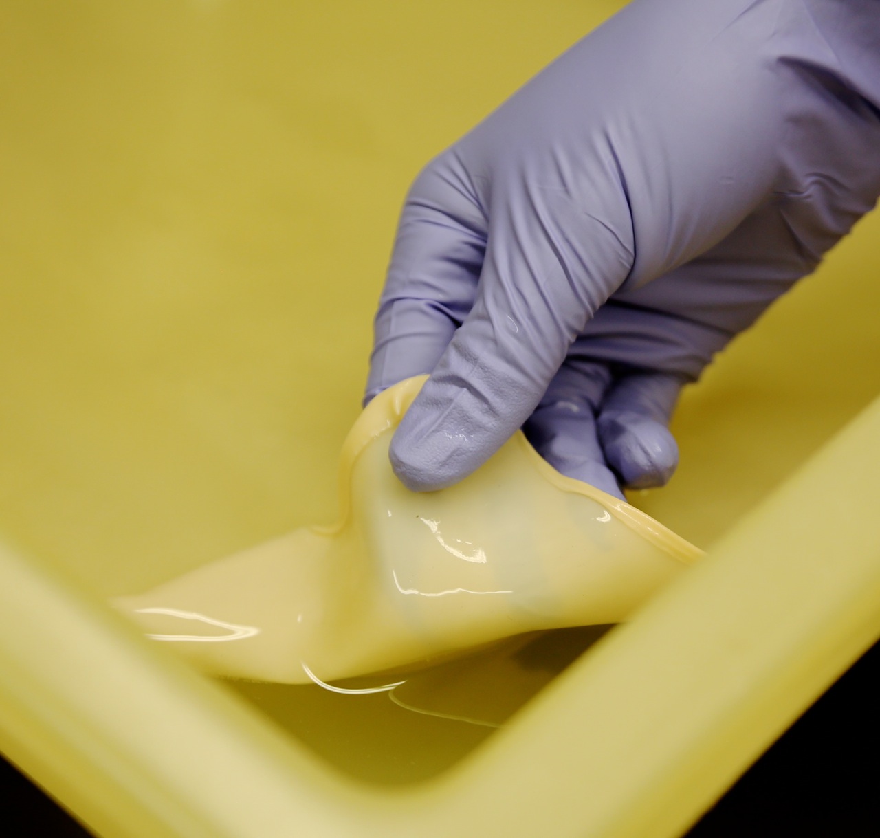
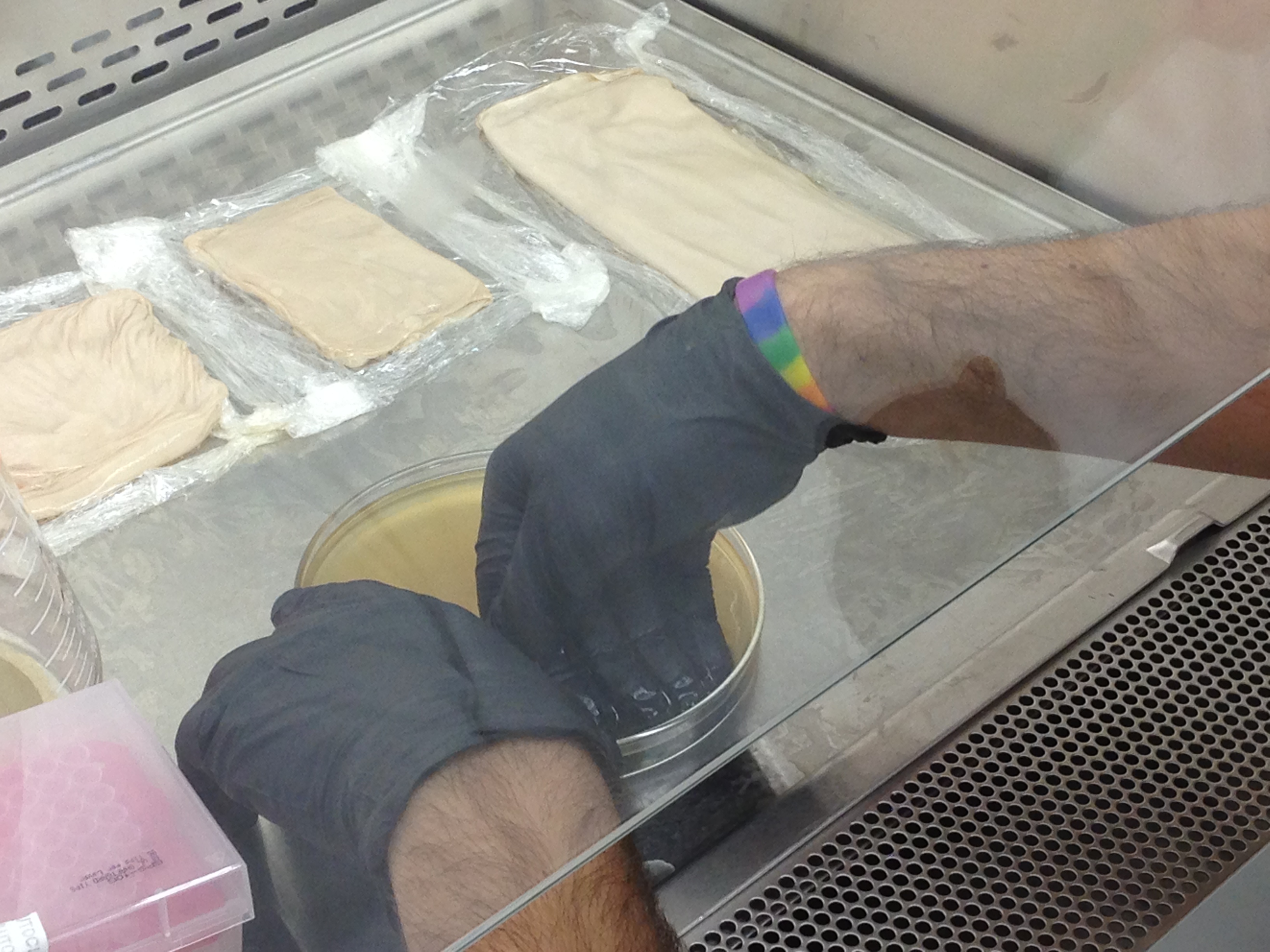
Our team modeled, prototyped, and collaborated with Ecovative Designto grow a mycelium-based chassis for our biological drone. Below you'll find process photos, part designs, and links to open source model files for downloading and additively manufacturing your own biological or bio-inspired unmanned aerial vehicle. Finally, you can see images of the biological, biodegradable UAV that we built and flew!
SBSiGEM2014BTD1.jpg?width=350
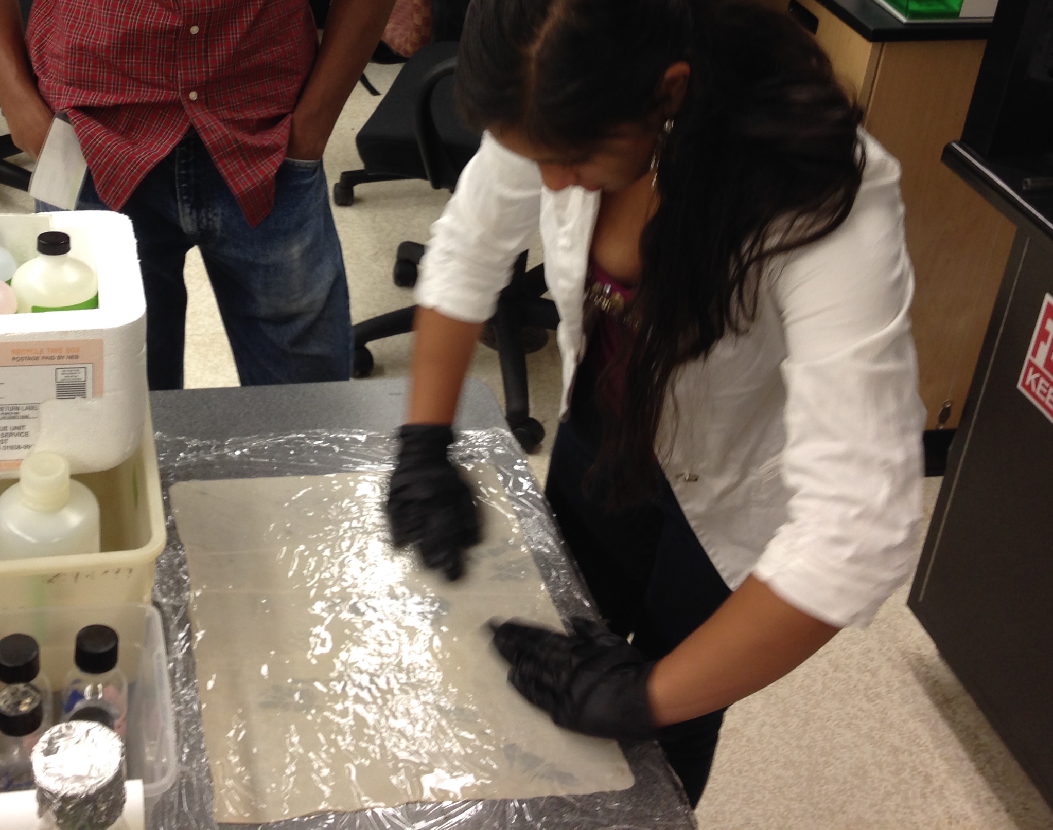
Harvesting a pure bacterial cellulose sheet.
SBSiGEM2014BTD2.JPG?width=350
Experimenting with cellulose material shape.
SBSiGEM2014BTD4.JPG?width=350
Layering cellulose to create thicker leather, see here at the back of the hood.
SBSiGEM2014BTD5.jpg?width=350
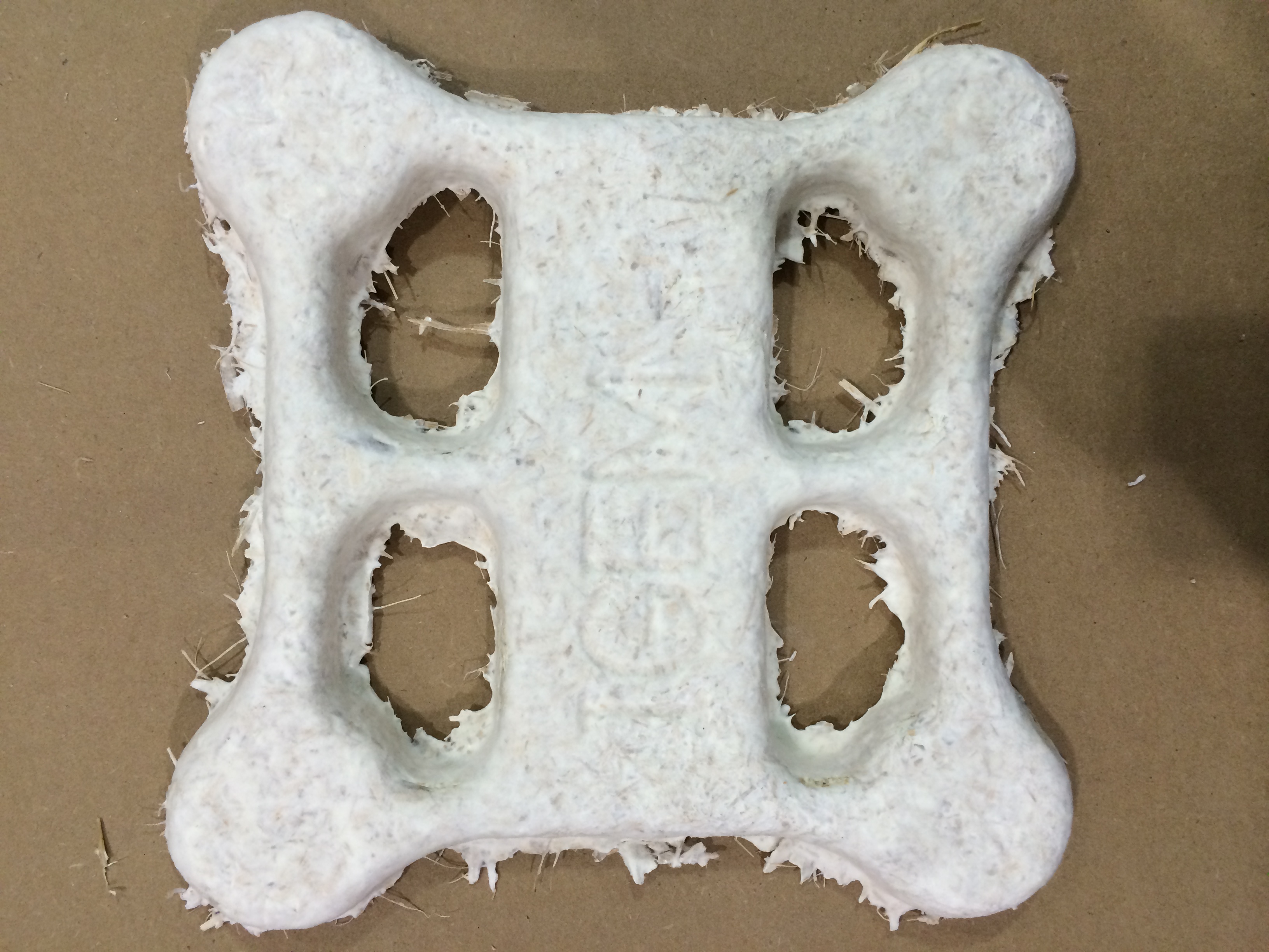
Mycelium drone chassis, modeled and 3D-designed by our team, produced by Ecovative.
SBSiGEM2014_Cellulose_Circuit.jpg?width=350
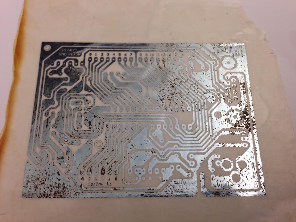
Our team collaborated with a silicon valley start up AgiC Inc. to print circuits onto our cellulose-based biomaterials in order to prototype how fully biodegradable circuitry might function on a biological UAV. See our Biomaterials page for details on the conductivity of this circuitry.
SBSiGEM2014BTD3.jpg?width=350
Variable thickness elements and experimental fragment attachment methods.
SBSiGEM2014BTD8.JPG?width=350
Spreading a cellulose sheet out to dry.

Starting Small, Ending Big
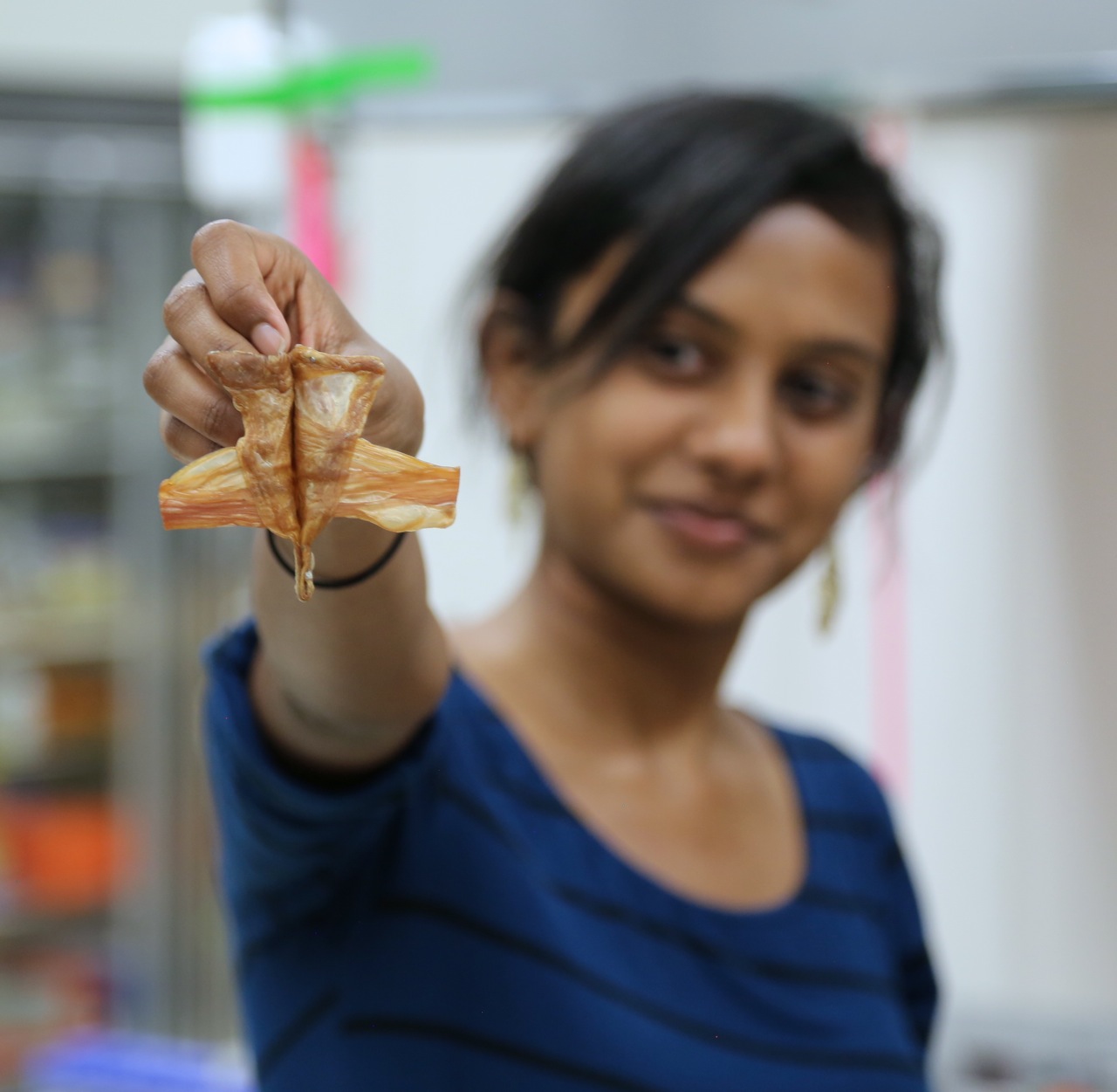
We began by experimenting with producing cellulose in sheets and cellulose acetate non-biologically. Seeing that primarily cellulose materials are extremely strong and tough, but tear easily and becomes soggy when wet, we sought to increase the durability of the cellulose by grinding it into pieces to create a cellulose paste (that became spreadable into sheets like paper made from wood pulp) and stretching and twisting it into ropes to add strength. A few of our material samples follow:

SBSiGEM2014_Cellulose_Screw.jpg?width=350
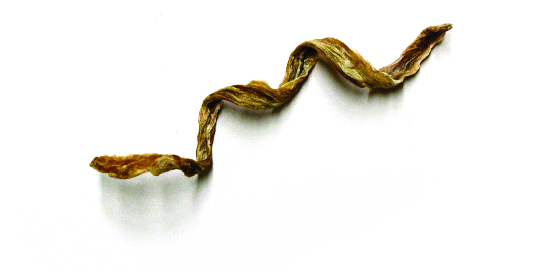
A spiral rope made by weaving together several cellulose sheets and dehydrating them.

SBSiGEM2014_Cellulose_Leather.jpg?width=350
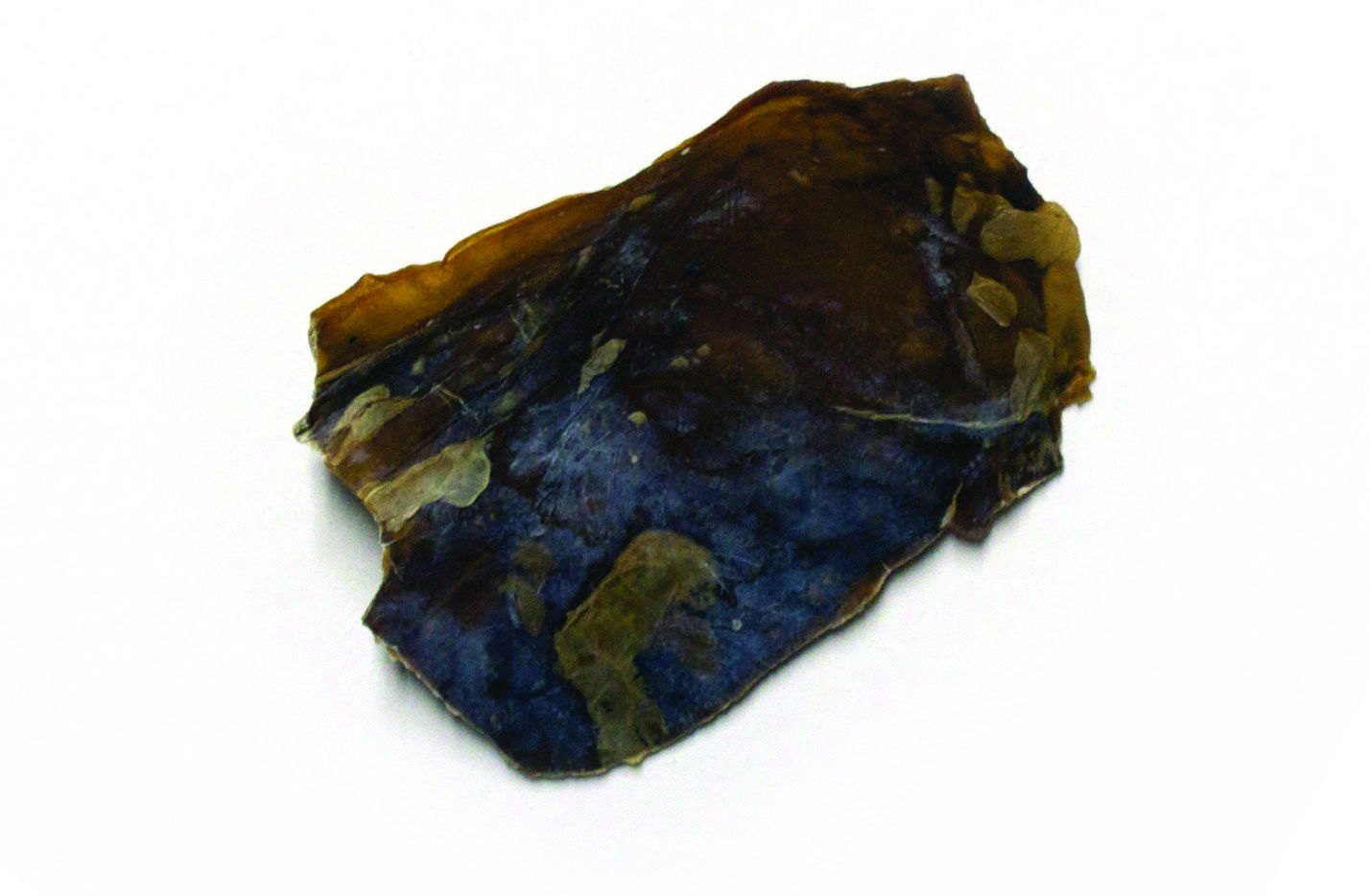
A piece of cellulose leather generated by laying multiple sheets of cellulose together in perpendicular orientations.
While experimenting with cellulose-based materials, we also explored traditional starch bioplastics to compare material functionality. Here is an example of a starch bioplastic that we produced synthetically in the lab:

SBSiGEM2014_Mycelium_Sample.jpg?width=350
Common starch bioplastic, which is more voluminous but less strong than bacterial cellulose. Starch bioplastics, like bacterial cellulose materials, suffer disintegration when wet.
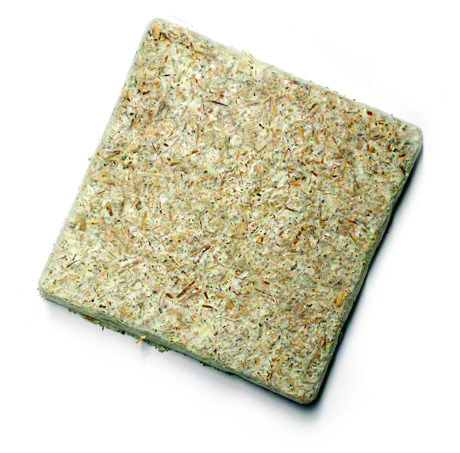
Realizing that cellulose acetate is tough but thin, our team was in need of a building material that was durable and lightweight. So, we reached out to Ecovative Design, a pioneering fungal-mycelium-based biomaterial company, to prototype a mycelium form that could serve as the chassis of our vehicle. Ecovative shipped us mycelium samples (pictured below), that we skinned in bacterial cellulose.

SBSiGEM2014_Mycelium_Sample2.jpg?width=350
6" by 6" by 1" sample of Ecovative's lightweight mycelium-based biomaterial.

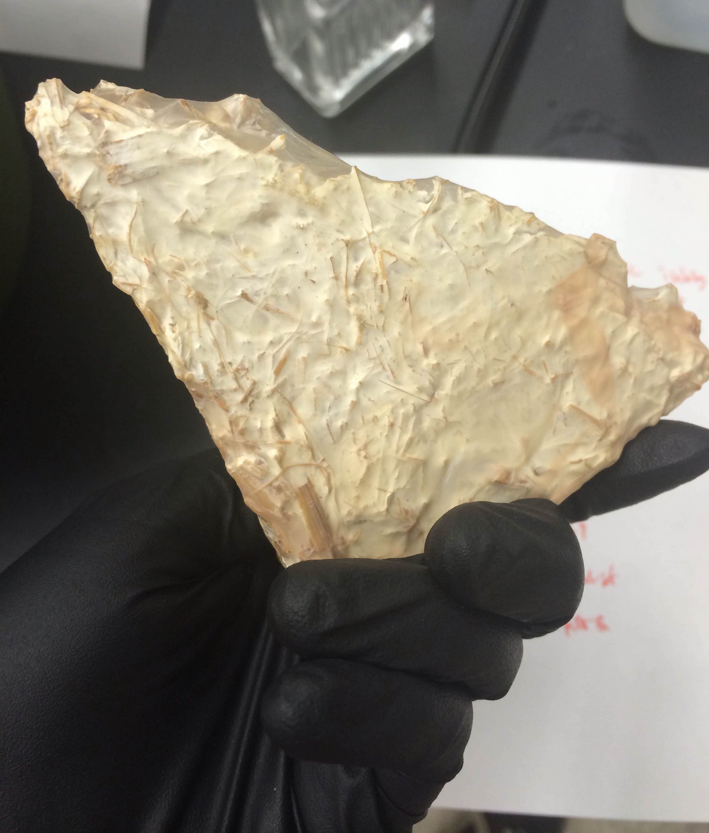
SBSiGEM2014_Skinned_Mycelium.jpg?width=350
A piece of fungal mycelium skinned in bacterial cellulose.
Thanks to Ecovative, we were able to construct a prototype biological unmanned aerial vehicle!

But we didn't stop there. Our team was enthusiastic about drone design and so we developed concept UAV designs meant to inspire future scientists and designers to think outside the box about how a future, partially living vehicle might look. Pseudo-natural and pseudo-industrial, our drone design references the traditional biological architecture of birds while embracing industrial additive manufacturability.

All 3D printable files for this concept drone are available in the downloads section. Images of our work follow:

Eli_Block_UAV_Design.jpg?width=350
Concept UAV Design

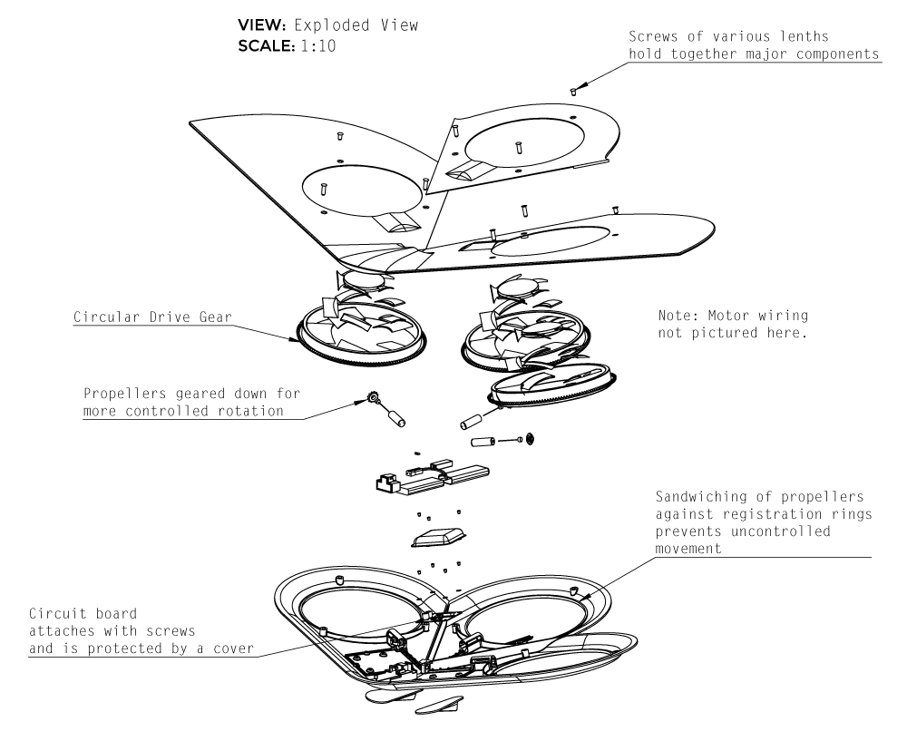
SBSiGEM2014_Exploded_Drone.png?width=500
Biological UAV Concept, Exploded View


Designed Parts & Downloads
We succeeded in producing multiple viable chassis designs for mycelium UAV concept prototypes. You can download our basic chassis designs here. If you would like to receive a copy of the designs for our more involved, final UAV concept (pictured above), then please reach out to us! We would love to share our work! In the meantime, download and check out our other models below:
SBS_iGEM_2014_download.png?width=75
Mycelium_Quad_1.SLDPRT: Download a 3D printable STL file for our mycelium quad chassic (pictured at top of page), which can accept four motors and serve as the foundation for a DIY biomaterial drone prototype.

Links & References
Interested in what we've been working on and want to find more relevant information? Check out some of the following sites, companies, and people who either aided us in our production of biomaterials or collaborated with us in working to produce a viable biological unmanned aerial vehicle.
● Ecovative — Fungal-mycelium-based biomaterial production company
● Miriam Ribul's Recipes for Material Activism documents bioplastic production with household ingredients
● Cooking Objects — Understanding objects, objectivity, and our relationship with sustainably produced, biodegradable household objects
● The NASA Space shop, providing resources and tools for rapid prototyping at the NASA Ames Research Center

Drone Futures
Here is a collection of drone-related sites and speculative work that stimulated our team to think about synthetic biology, the future, and the role of personal unmanned aerial vehicles or biological devices in an evolving world of DIY craft, government surveillance, and channelled creativity.
● Frabrica — Drone, speculative fictions in the age of the drone
● Drone Survival Guide — a poster series highlighting the uneasy relationship between the public and drones
● DIY Drones — a growing online community of makers committed to building unmanned aircraft
● Drone shadows, a visual reminder of constant surveillance
● Anti-Drone hoodie

SBS_iGEM_2014_twitter.png?width=50   SBS_iGEM_2014_insta.png?width=50   SBS_iGEM_2014_link.png?width=50

sbsigem@googlegroups.com
View our Complete Project List
Meet our team!

link to the original post   here
Read more…

Does DJI’s New Drone Hit the Target Market?

3689626099?profile=original

This post also appears in sUAS News ‘The Market‘.

---

I think it’s futuristic – the drone that is.  The camera, on the other hand, is another story.

The drone

For a guy like me who not only follows the commercial market for drones but is also an avid photography and multirotor enthusiast, the new DJI Inspire 1 is, well, inspiring. It’s chock full of features I wish I had four years ago when I first started mounting GoPro cameras on quadcopter kits -- things like ease of use, a simple interface, controller ergonomics, telemetry, a 3D-axis gimbal, integrated HD video downlink, optical flow for indoor flying (how cool is that!?).

Much has already been written on the Inspire 1 T600 (like here and here) so I won’t repeat it.  The question for this post is: Did DJI hit the mark for the target market?  For that answer, we need to go beyond the drone itself and look at how professional photographers and videographers use drones and cameras.

Read more here: http://droneanalyst.com/2014/11/16/dji-new-drone-hit-target-market/

Read more…
MR60

433 Mhz antenna comparison - DIY & standard stock models

3689626007?profile=original

Within AirbotServices.com, all of our professionally built drones integrate a live telemetry link, outside of the main transmitter frequency band. We consider it to be a critical safety element that should be enforced in future European regulations for commercial drone activities. It is a must have. Why, you may ask ?

The current relative lack of reliability inherent to complex electronics and software modules composing a drone (although it may integrate redundancy) will sooner or later inevitably translates in "gremlins" during flight (a priori unexplained bugs) and/or eventually flyaways (uncontrolled drones).

Telemetry provides multiple safety functions:

-A safety functionality by monitoring real time critical elements that should be taken into account by the pilot (battery level typically)

-A safety functionality by sending real-time positionning (GPS) data on the ground station which can be used to find your drone that flew away;

-A debugging functionality by providing real-time to the ground the values of internal parameters (and therefore helps finding out why there is an uncontrollable behaviour);

-A logging functionality (Tlogs);

-An out-of-band communication outside the Radio transmitter band (it the 2.4ghz fails, the telemetry link might save you); not only to receive flight parameters on the ground but also to send  commands.

433Mhz is the frequency of choice for telemetry as it provides the best range & penetration capacity through objects and walls versus higher frequencies (i.e. 900 Mhz or higher).

In Europe the maximum power allowed for using 433Mhz band, for other uses than amateur radio (for which an amateur radio license allows you to use hundreds or thousands of watts), is 10 milliwatts. This band is used for house alarm systems, remote controlled devices, etc.

Such a small power allowance makes it critical to optimize antenna designs on our drones, to maximize the range.

On the test bench : 4 different 433Mhz antenna models:

We will compare hereunder various 433Mhz antenna models, some are commercial stock models, others are DIY models based on best practices, among which excellent build advices provided on this diydrones blog:

http://diydrones.com/profiles/blogs/dipole-style-antenna-for-433mhz?id=705844%3ABlogPost%3A1674324

  • 3DRobotics model:

The standard 3DR duck telemetry antenna such as shown here

3689626041?profile=originalis a 2Db compact sleeved dipole. It is sold with the 3DR telemetry kit.

  • Nagoya 144/433 Mhz model :

3689625865?profile=original

Nagoya is famous for building excellent antennas. This is their telescope antenna, model NA-773.

  • AirbotServices' sleeved dipole model:

This is a 433Mhz model built by AirbotServices, designed by Joe ("Nampilot") as described in the blog link above,

3689626051?profile=originalIt is made of 100% copper. Contrarily to simple dipoles where the two active elements have the same length and are fed in the middle (wich requires a balun to balance it to 50 ohms), this dipole consists of a longer top copper wire and a shorter copper tube which acts as a balun at the same time. The resulting antenna is not only perfectly tuned for 433Mhz, it is also 50ohms balanced without an additional balun.

A RG316 cable feeds this antenna.

  • AirbotServices simple (standard dipole) model:

3689626063?profile=originalThis is the classical dipole with servo wire and a RG316 feeding coax. We added a ferrite choke as a balun. The center is reinforced with balsa to maintain 90 degree angle between the active elements and the feeding coax.

Test method and results:

We use the RF explorer spectrum analyser as our test equipment. Rather than using its small integrated LCD screen, we used the windows PC client software, connected by USB to the RF explorer.

The test signal was picked purely and simply in the ambiant "433Mhz band" signals. At the moment of the test, a particular peak signal was found at about 424-426Mhz. It is not an issue to measure aside the pure 433Mhz frequency as the telemetry device uses frequency hopping between 414Mhz and 454 Mhz.

So each tested antenna were screwed one after the other on RF explorer and we waited for a stabilization period. After which the signal DB levels were measured as follows:

The 3DR duck style Model:

3689626111?profile=originalThe 3DR duck style antenna measures a -78Db signal level.

The Nagoya antenna model:

3689626076?profile=originalThe Nagoya antenna measures a -69Db signal level.

The AirbotServices sleeved dipole model:

3689625882?profile=originalThe AirbotServices sleeved dipole model measures a -69.5 Db signal level.

The AirbotServices standard dipole model:

3689626157?profile=original

The AirbotServices standard dipole model measures a -73.5 Db signal level.

Conclusions:

-The base 3DR duck model provides the least performance as we could expect, fixing an arbitrary base a reference level of -78Db

-Both the Nagoya and AirbotServices sleeved dipole provide the best performance, improving the measured signal by 9Db relatively to the base 3DR model.

-The standard dipole model lays in between with -73.5Db, which  is still 5Db better than the 3DR model. It was also noticed during the measurements that this dipole is quite sensitive to polarization : a difference of 5Db could be measured by rotating the polarization. This sensitivity was not noticed that much with AirbotServices sleeved dipole.

There you have it, our quick telemetry 433Mhz antennas test bench.

Cheers,

Hugues

Read more…
Moderator

In this video is possible to see, the first long range test of  one of advanced functionality that  will be available in a new pro revision of VR Pad station , with this feature is possible recive in realtime a streaming in h.264 with latency near 300  ms. The new feature support : Wifi - 3G - 4G LTE . With Video streaming you recived in realtime the telemetry data from the drone. 

Another interesting video about a new advanced follow me functionality that will be available on VR Pad Station and VR Leash ,too 


3689596642?profile=original

VR Pad Station is an app that turns your Android smartphone or your pad into a ground station combined with a powerful digital remote control radio for use with your RC model or with your drone. 
Is designed to be used on Rover, Airplane or Drones for hobby and professional use. It 's a project dynamic and evolving based on feedback from users of our community: www.virtualrobotix.com
It use mavlink 1.0 and support the firmware APM Copter , Plane and Rover

The current version is a preview suitable only for BETA testing use it carefully.
Use VR Radio only with the simulator, until new updates.

In Version 2.1.0 we adding the support for new VR Gimbal that use mavlink protocol for setting and control the camera . This is last video of new gimbal with mavlink support that use the mission planner mavlink but will be support of our new VR Pad Station  : 

Version 2.1.0

- Updated USB serial library (need more test)
- Added USB compatibility for VR Micro Brain
- Added VR Gimbal configuration panel
- Added a confirmation dialog when enabling RC override
- Improved communication handling
- Improved device compatibility with less requirements
- Fixed some crash problems
- Fixed other bugs

Version 2.0.9
- Added MavLink telemetry logs option
- Fixed FollowMe and Guided Mode
- Fixed "out of memory" problems on some devices
- Fixed a problem where gimbal parameters are not downloaded automatically inside settings
- Fixed crashes on loading airports
- Fixed a bug during arming

Version 2.0.8
- Fixed HDOP decimals
- Added confirmation dialog for ARM/DISARM/TAKEOFF
- Sticks are aligned to the RC of the drone before override
- Separated acc calibration from mag calibration panel
- Added button in mag calibration for compare the drone yaw with the device gps yaw
- Screen never in standby
- Added support to 19200 and 38400 serial baud rates
- Added solar radiation level info inside overview panel

Version 2.0.7
- Changed USB serial library, now it supports more devices

Version 2.0.6
- Added failsafe configuration settings

Version 2.0.5

- Added radio calibration in GCS settings;
- Added airports locations on map, in an area of 100km from user/drone position, activated from map settings;
- Fixed minor bugs;

Version 2.0.4

- Corrected gimbal settings layout on smartphones
- Added waypoint commands
- Long click on a waypoint in the list opens an editing dialog
- Option for setting the zoom when auto-pan is enabled
- Added option during the generation of polygon for set the altitude
- Added, where available, range/units/values of parameters
- 3D map in some areas with normal map type
- Now you can interact with map in the VR Radio, if RC override is not enabled
- Fixed an error in VR Radio where the channels goes directly from RC_MIN to RC_MAX
- Added failsafe and sensors status into HUD
- Added HDOP indication in the action bar

In the new revision 2.0.3 is available

  • A new info bar with a lot of usefull information battery level , gps status , active mode .
  • A new follow me standard mode .
  • Only one connection for different application.
  • Parameter setup for gimbal.
  • New configuration option pannel .
  • New advanced user interface compatible not only with PAD but also with Smartphone android device.
  • A early revision of VR Glass Station a special revision that work on Google Glass device.

We are work in progress with some advanced features as Special follow me mode , Fligh log book and VR Gimbal integration and advanced low latency h.264 video trasmission.

The App is compatible with APM Copter , Plane and Rover.

Inside the community could be possible discuss directly with developer about the new request feature .

Join us in beta testing this is the direct link to google store : 

https://play.google.com/store/apps/details?id=com.laser.VrPadStation

 Google Community Group for manage the beta testing of VR Pad Station continue to join new member  this is the link : 

http://plus.google.com/communities/102697330643558260161

This is the official Virtual Robotix Discussion group about VR PAD Station 2.0.3 :

http://www.virtualrobotix.com/group/vr-pad-station-2-0

Feedback about our application are welcome ... :) In the next week we intend improve VR PAD Station with new feature under development.

Best

Roberto

Read more…
Moderator

This is a video example of how you can add the telemetry module to VR micro brain and test the board with VR Pad Station. Now is possible to connect directly VR micro brain and VR micro Gimbal to VR Pad Station by a usb OTG cable.

These are the board developed by VR Lab : VR micro Gimbal , VR Multi Constellation GPS 8  ,VR Micro Brain and plug and play VR micro telemetry board .

3689625646?profile=original

Example how is possible to assemble  the boards togheter , the form factor is very small and lightwheight . 

3689613300?profile=original

In the picture below is presente the VRX Radio Module lite , Standard and Advanced ( OSD support ) 

3689625833?profile=original

This is an a video example of new VR micro Gimbal in action.

This is a very exclusive video  example of fully autonomous fly using VR Leash experimental kit . You can set the position where put the drone by VR Leash natural reposition system or by PAD / Smartphone user interface available in VR Pad Station Pro.

Some of board use in these drone is already available : 

VR micro Brain APM Copter rev 3.2 : http://www.virtualrobotix.it/index.php/en/shop/autopilot/vrbrainmicro51-detail   

VR GNSS 8 (support GPS ,Glonass and Egnoss ): http://www.virtualrobotix.it/index.php/en/shop/accessories/gps-ublox-8-detail

VRX uBrain Telemetry module lite option 433 : http://www.virtualrobotix.it/index.php/en/shop/accessories/vrx-ubrain-radio-module-lite-433-mhz-europe-38-61-detail

VR uBrain Telemetry module lite option 868 : http://www.virtualrobotix.it/index.php/en/shop/accessories/vrx-ubrain-radio-module-lite-868-mhz-europe-38-61-62-detail

VR radio module lite option 433: http://www.virtualrobotix.it/index.php/en/shop/accessories/vrx-radio-module-lite-433-mhz-europe-38-detail

VR radio module lite option 868: http://www.virtualrobotix.it/index.php/en/shop/accessories/vrx-radio-module-lite-868-mhz-europe-38-61-detail

VR micro Gimbal Board :  will be available at december 

VR Leash : available for OEM and Pro project.

Best

Roberto

Read more…
Developer

APM:Rover 2.47 Released

3689625704?profile=originalThe ardupilot development team is proud to announce the release of version 2.47 of APM:Rover. This is a minor bug fix release. The most important change in this release is the fixing of the skid steering support but there have been a number of fixes in other areas as well.

Full changes list for this release:

  • add support for controlling safety switch on Pixhawk from ground station
  • prevent reports of failed AHRS during initialisation
  • fixed skid steering that was broken in the last release
  • report gyro unhealthy if gyro calibration failed
  • fixed dual sonar support in CLI sonar test
  • fixed Nuttx crash on Pixhawk with bad I2C cables
  • added GPS_SBAS_MODE parameter - turns on/off satellite based augemtation system for GPS
  • added GPS_MIN_ELEV parameter - specifiy the elevation mask for GPS satellites
  • added RELAY_DEFAULT parameter to control default of relay on startup
  • fixed bug in FRAM storage on Pixhawk that could cause parameters changes not to be saved
  • better handling of compass errors in the EKF (Extended Kalman Filter)
  • improved support for linux based autopilots
  • added support for PulsedLight LIDAR as a range finder


Many thanks to everyone who contributed to this release, especially
Tom Coyle and Linus Penzlien for their excellent testing and feedback.

P.S. Hi all - I am helping Tridge with Rover development and this is my first release announcement.

Happy driving!

Read more…

Dear All,

As we are now have finished the belt drive design as you can see, we are now in the making of it. Once we have tested one unit we can see how it functions, (acceleration, control, stress, vibrations, etc..). But yes always there is to be 

3689625675?profile=original

a plan B. And good to advance in that direction too. That craft would be configured just like the original see earlier blog. But at each end iso one e motor with belt, there would be two motors:  one up one down (just like in some quadrocopters). This would be a compact alternative with more redundancy. 

The motors would be controlled separately and we can vary the top and bottom speed. 

We see at first investigation that contra rotating props can have some higher efficiency as 2 seperate ones. We also understand that the prop pitch of the lower prop needs to be higher as the down wind it receives from the top one can then better be used.  

Now the issue is: does any one of you have experience or rules of thumb or simple first effect formulas to tackle the issue? Would think that with the some of the drones this issue must have been studied?

Hope to hear, Best Regards, Winfried team www.TheHummingManProject.com

Read more…

DJI T600 Inspire - Hobbyking

75615.jpghttp://www.hobbyking.com/hobbyking/store/__75615___PRE_ORDER_DJI_T600_Inspire_1_Quadcopter_with_4K_Camera_and_3_Axis_Gimbal.html

This DJI mutirotor is going to flood the market and with a price tag of $2,899.00 will hopefully keep it out of the beginners hands.

Features:
• Completely READY-TO-FLY
• Innovative transforming design for 360° aerial photography / video
• Leading edge camera for 4K video & 12 megapixel photos
• Modular camera gimbal design for easy transportation & upgradability
• 720p HD Live video output
• Support dual transmission system – photographer & Flyer can control the gimbal & model separately (A extra transmitter is required)
• Optical Flow technology combined with sonic waves rise indoor flying stability to a new level
• Intelligent battery with advanced algorithms – It can calculate the distance of your Inspire 1 from you and keep tracking your battery status, so you can manage the flight time better
• Specially design transmitter to fit FPV needs - Dedicated buttons for photo and video capture, a gimbal control dial, an integrated rechargeable battery, HDMI and USB port allowing you to connect mobile devices or compatible screens.
• 1-click take-off & landing
• Return-to-Home function
• Smartphone controllable

Specification:
DJI Inspire
Weight (Incl. Battery): 2935g
Hovering Accuracy (GPS mode): 0.5m(Vertical), 2.5m (Horizontal)
Max Angular Velocity: 300°/s(Pitch), 150°/s (Yaw)
Max Tilt Angle: 35°
Max Ascent Speed: 5m/s
Max Descent Speed: 4m/s
Max Speed: 22m/s (ATTI mode, no wind)
Max Flight Altitude: 4500m
Max Wind Speed Resistance: 10m/s
Max Flight Time: Appro. 18 minutes
Motor Model: DJI 3510
Propeller Model: DJI 1345
Indoor Hovering: Enabled(Default)
Diagonal Distance: 559 to 581mm
Dimensions: 438x451x301mm

Gimbal
Model: ZENMUSE X3
Output Power (with camera): 9W(Static), 11W(In motion)
Operating Current: 750mA(Static), 900mA(In motion)
Angular Vibration Range: ±0.03°
Mounting: Detachable
Controllable Range: -90° to +30°(Pitch), ±320°(Pan)
Mechanical Range: -125° to +45°(Pitch), ±330°(Pan)
Max Controllable Speed: 120°/s(Pitch), 180°/s(Pan)
Camera
Model: FC350
Resolution: 12.0MP
FOV (Field of View): 94°
CMOS: Sony EXMOR 1/2.3”
Lens:
f/2.8 (20mm equivalent)
9 Elements in 9 groups

Aspherical lens element
Anti-distortion filter
UV filter
Still Photography Modes:
Single shoot
Burst shooting (BURST: 3/5/7 frames, AEB: 3 or 5 bracketed frames at 0.7EV Bias)
Time lapse
HD Video Recording Modes:
UHD (4K): 4096x2160p24/25, 3840x2160p24/25/30
FHD: 1920x1080p24/25/30/48/50/60
HD: 1280x720p24/25/30/48/50/60
Max Bitrate of Video Storage: 60Mbps
Supported File Formats: FAT32/exFAT
Photo: JPEG, DNG
Video: MP4/MOV (MPEG-4 AVC/H.264)
Supported SD Card Types:
SD/SDHC/SDXC Micro SD
Max capacity: 64GB, Class 10 or above

Transmitter
Operating Frequency:
5.728GHz~5.850 GHz (Transmitter to Transmitter)
2.400GHz~2.483GHz (Transmitter to radio)
EIRP: 13dBm@5.8G, 20dBm@2.4G
Video Output Port: USB, HDMI
Dual User Capability: Host-and-Slave
Output Power: 9W
Battery: 6000mAh LiPo 2S

Battery
Capacity: 4500mAh
Voltage: 22.2V / 6cell
Energy: 99.9Wh
Net Weight: 570g

Vision Positioning
Velocity Range: Below 8m/s (2m above ground)
Altitude Range: 5cm-500cm
Operating Environment: Brightly lit (lux >15) patterned surfaces
Operating Range: 0-250cm

Included:
Inspire 1 Quadcopter
Transmitter
ZENMUSE X3 Gimbal and Camera
Charger
Smartphone Holder
4 x Spare Props

$2,899.00

Read more…

3689625481?profile=original

Hi there, another update on the blog I wrote last week which showed how to make a cheap ($50) wireless fpv monitor. This week, I updated to show how to convert the cheap hacked together wireless monitor, and using a cheap $2 fresnel lens we can make immersive goggles, either by cutting up cardboard and fixing with sticky tape, or buying a head mount like in this right image. The head mount is still pretty cheap at £14.05 but in the spirit of DIY, I suggest making your own

Update is at the bottom of the blog article. Hope this helps and inspires some peeps.

Article here: http://dalybulge.blogspot.co.uk/

Happy flying :)

Read more…