Posted by Quadzimodo on December 2, 2014 at 8:30pm
The DreamQii team closed out their hugely successful Plexidrone campaign on Indiegogo just a few days ago after passing the big $1million milestone and reaching all it's planned stretch goals - unlocking upgrades including a heavy lift X8 conversion and heavier pro focused gimbal designed for larger mirrorless imaging devices.
It is a clever design which clearly aims to address a number of the issues that detract from the experience of flying a multirotor. The PlexiPower Battery Pack saves the cumbersome process of fastening a conventional lipo and labouring with stubborn connectors, however does lock users into purchasing DreamQii's proprietory packs. Spin on props ensure secure fitment and allow you to swap out blades with ease. The modular system also allows for compact storage yet fast setup time, while facilitating easy replacement of arm and motor assemblies in the field (should something go wrong) without the need to fidling around with any tools.
The Plexidrone has also undergone somewhat of a transformation in terms of design over the past few months, and now looks far more polished and resolved than the earlier 3D printed prototype which began it's campaign back in early October.
While the initially planned campaign has now ended, the Plexidrone and it's list of ancillaries are still available thanks to a new Indiegogo initiative called 'forever funding'.
3DR is hiring more engineers, in our Berkeley office. APPLY HERE!
We're growing fast and working on some really neat new products. Hope you can join up!
Specific roles include:
EE
ME
Embedded SW
Mobile developer
Flight test engineer
What we are looking for We are looking for candidates who have proven expertise in creating well-designed, robust, and delightful systems in end-user products (did you work on a smartphone? how about the roomba? an electric car? that's the kind of work we hope you've done), an ability to quickly improvise and iterate, and a passion for building innovative technologies - and building flying robots (natch).
I'm pretty dang sure there are a lot of folks in the community here that would really enjoy working full-time at 3DR and have super amazing talent levels ... so I hope you get in touch. The time is now! :)
Posted by Quadzimodo on December 2, 2014 at 7:42pm
Australia & New Zealand's favourite electronics retailer and specialist supplier to the electronic engineering community, Jaycar Electronics, just uploaded a few videos showing the latest addition to their extensive product range - The Skymaster Professional Quadcopter.
Jaycar Electronics have been slowly growing their RC category over recent years with toy boats, Gas and EP buggies, planes and just about every type of micro copter imaginable. In the lead up to last Christmas they introduced the Mega Quadcopter and initially couldn't keep them on the shelves. This year they are offering something much more serious.
Faux telescopic legs and oversized landing pads give the Skymaster a rather toy like retro sci-fi look, while a large LED indicator provides visual confirmation of pre-arm and GPS status. Two colour prop nuts suggest self tightening CW and CCW prop mounts are provided, offering convenience and reliability over lesser alternatives. A standard camera mount is available which is suitable for a range of action cameras and a 2-axis brushless gimbal (which appears to be the Tarot 2D V2) is also offered for Hero 3 users who seek out-of-the-box stabilised aerials.
The product copy reveals little about the flight controller, but it is a pretty sure bet to be something like the APM 2.52 V2.0, Devo-M or simular. Firmware is no doubt a custom variation on Arducopter 3.1.5
It doesn't look like a telemetry radio is included, limiting functionality somewhat while making it a simpler, easier and cheaper proposition for new flyers. With a little luck bluetooth or UHF link might well be possible. Jaycar fans will make short work of an easy hack so to unlock all the added convenience and advanced functionality Mission Planner and DroidPlanner can provide. What options exist in regards to firmware compatibility and upgradability remains to be seen, but it would be great if the Skymaster could be tweaked to offer all the polish and power afforded by the recent 3.2 release of Arducopter , a solid UHF radio link and Droidplanner 2 (and, by extension, the added functionality of tools like DroneShare).
Priced at an RRP of $699 for the bare RTF system, the Skywalker is not exactly priced aggressively. Nevertheless, Jaycar will not struggle to find a demand among their legions of tech-hungry gadget-friendly fans. In fact, I reckon the Skymaster is going to absolutely fly off the shelves in the lead up to and beyond the holiday period - introducing thousands of new users to the wonderful world of drones over the weeks and months ahead.
In the Albatros UAV, a new design after Barcelona 3d printed UAV, I'll test a moving mass (batteries) control and an aeroelastic wing for the aileron surface. What do you think about that?
Posted by Glen Sanders on December 2, 2014 at 1:30am
Hi there,
Thought it might be good to post some info on a 'Heavy' Tricopter based on the rcexplorer design. It's now up to 1.85Kg and is going great. It's built on David Winestal’s plates from flitetest with wooden booms. The added weight has happened because I desired stabilised video.
The best performance boost was switching from 3S to 4S batteries, (just noticed I haven't updated the schematic lately oops :-)
So to that end it now has a tarot 2d gimbal, APM 2.6 flight controller, 4S 5200mAh lipos, 850Kv motors with 11x5 graupner e-props. She goes well and I get a good 15 minutes flight time, up to 70Kmhr and 40 degrees of pitch without losing height. It's been out to 1.8Km on 2.4GHz rc and 5.8GHz (600mW) video RHCP....
I've linked a video in case you'd like to see the result....
Posted by Patrick Meier on December 1, 2014 at 1:00pm
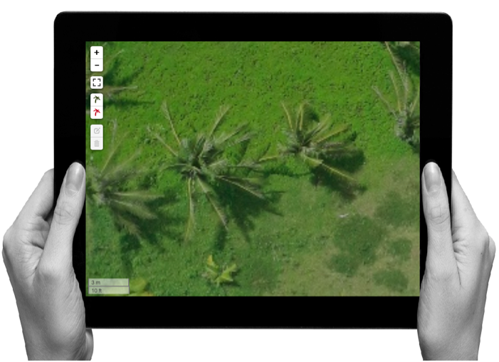
More than 30 million coconut trees were destroyed by Typhoon Haiyan in the Philippines. This has had a devastating impact on local livelihoods. To make matters worse, the rotting trunks of uprooted coconut trees has let to an infestation of the Coconut Rhinoceros Beetle, which is destroying the remaining healthy trees in some areas. So the Humanitarian UAV Network (UAViators) has teamed up with the Filipino UAV company SkyEye to crowdsource the analysis of thousands of aerial photographs that were recently taken of affected areas. This week, hundreds of digital volunteers from around the world will use the MicroMappers website (screenshot above) to trace the trunks of healthy and unhealthy trees.
The results will enable our humanitarian partners to assess the current situation. We will also use the resulting data to create machine learning classifiers so that destroyed coconut trees can be automatically detected in future aerial imagery. This has applications will beyond the Philippines since many disaster prone countries in tropical areas grow and depend on coconut trees as a source of livelihood.
To take part in this crowdsourcing effort join the MicroMappers list-serve here simply send a blank email to MicroMappers+subscribe@googlegroups.com. The project will start on Friday, December 5th at 12pm London time (GMT) and will run until 8pm Sunday, December 7th (end time is variable). So check your emails on December 5th; we’ll send out an email at 12pm with the link you’ll need to volunteer. This link will first lead you to a tutorial which will include a short video on how to use MicroMappers to trace the trees. This is very simple to do, which means no prior experience is necessary.
Our previous deployment of MicroMappers, which also used aerial imagery, focused on wildlife protection in Namibia and was recently featured on CNN here.
Posted by Colin Snow on December 1, 2014 at 10:24am
What if you could talk to a drone? No, seriously. You can already talk to a locomotive, so why not talk to a drone?
For those of you following the technology, you already know that unmanned aircraft systems (a.k.a. drones) are finding their way into Internet of Things (IoT) implementations. IoT applications are typically composed of:
A sensor “at rest,” e.g., on a highway or a bridge or a thermostat that gathers input (like weather conditions or seismic activity)
A connection (via the Internet) between the sensor and a back-end data collection infrastructure
A back-end data collection infrastructure that’s commonly based in the cloud
So why do I claim that drones the future of IoT? For one, drone technology is evolving very rapidly. Drones are already beginning to efficiently replace the connected sensors at rest with one device that is:
deployable to different locations
capable of carrying flexible payloads
re-programmable in mission
able to measure just about anything, anywhere
To illustrate the trend and these capabilities, I’ll highlight the developments of several companies. But first – so that we are all on the same page - let’s look at what I mean when I talk about drones.
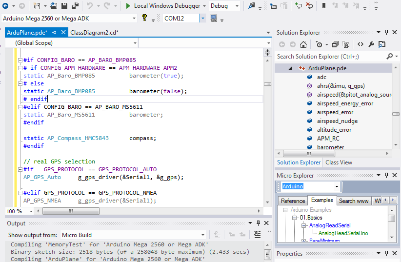
Microsoft has release a full featured version of Visual Studio 2013 free for open source projects or personal use and small business users.
This is great news for the the Visual Micro Arduino IDE plugin. The Visual Micro guide for APM is located here and Visual Micro can be downloaded from here
Until now, developers who did not own a copy of Visual Studio have been able to use Atmel Studio for their Arduino/APM development (Atmel Studio is based on Visual Studio 2010).
Visual Studio 2013 brings a number of additional benefits over Atmel Studio such as great code visibility and powerful code explorers.
Last Friday I had fun witnessing Diether Engelhard and Andreas Breitenstein pulling off four 1hr flawess flights in one day with their APM1 equipped X8 to map some 900 hectares of farmlands in Namibia. The X8 covered a total distance of 240km to provide high resloution aerial imagery - altogether some 9000 20MP images captured with a Samsung NX 1000 camera. This is a classic example of how small, private sector enterprise entrepreneurism and initiative can lead a country to self sufficiency in mapping. Instead of procuring in the expensive coorporate international markets, often advantaged by donor country governments or international finance institutions, Namibia can now turn to it's very own small enterprises to intelligently update and enhance geo-spatial information as and where needed. The true agents of technology transfer, innovative applications and capacity building in the developing world are unfortunately all too often overlooked by the international development sector.
Have you ever think about controlling multiple drones, or enjoying a team flying with your friends, where you can both monitor your drones, even your friend who could not come to the field, even your friend in another country !!
If this is not enough lets imagine you need to fly your Ardu drone in a very long mission, and you need it to be connected with your ground station or Droid Planner, you need no expensive devices anymore.
Imagine you need your Ardu to follow your friend Multiwii, different platforms, well this is a comming soon feature :) rest are already there.
Let us start the story from the beginning. Mobile devices are getting more powerful every day, as in 2014 many mobiles have multiple cores with speed more +2GHz, and +1GB Ram. Recent mobile phones have complete set of sensors Gyro, Accelerometer, Magnetometer, Barometer, GPS as well as rich communication media including Bluetooth, Wifi and GPRS. This is not everything, even mid-range mobiles have powerful camera with very high resolution.
They also have loud speakers and high resolution screens with multi-touch capabilities. That makes mobile a very attractive platform for RC and UAV.
A board with same features would be quite complex to assemble and will require a lot of programming challenges to make these stuff work together, meanwhile an Android mobile provides these features with relatively easy programming and in high level languages such as Java or C++.
People have stopped thinking of mobiles as a classical phone since a while, and it is seen as an integrated device where you can talk to ppl., watch movies, listen to music. The Andruav project adopts the same vision in UAV world, hence your mobile is your own new control board.
So what is Andruav –pronounced “androiv”-. It is an interconnected Android-based mobile that allow both vehicle-to-vehicle and vehicle-to-GCS communication and control. It allows group communication, and drone-to-drone communication.
Currently the system is in its Beta Stage. I hope interested people can join to get the best out of this.
Posted by Chris Anderson on November 28, 2014 at 11:00pm
Very nice work by Ioannis Kedros here. It's an APM-compatible PDB that allows for all sorts of copter configurations, from X and + to Tri and even "spider". Here's more (via Hackaday):
I’ve start building multicopters (or drones if you like it better) five months ago! My first one was a scratch build tricopter based on a KK2.1.5 flight controller and three DT750 motors. Everything was made out of plywood and pinewood! It held excellent if you consider that I was a newbie pilot (still I am) and I had something like 3-4 crash reports per flight!
Two moths ago I decided to go a step further and make my second multicopter. This time it will look a little bit more professional than my previous one! To begin with it will be a quad copter, carry a better flight controller, reuse parts of the previous build (in order to lower the cost) and it will be able to stay above the ground longer.
And if you wondering how my first attempt to build a multicopter looked like, I am planning on making an article about that but you can have a sneak peak on the picture below
Yeah! It looked ugly but it worked far better that I was expecting! So, going back to the quadcopter now! Somehow I should address the key points that I’ve set above. First the looks of it!
In order to do that you can buy one of the multiple available frames out there. They come in different sizes, build materials, strength levels, colors etc. The only thing you have to do is to assemble the frame, add the components you want and you are ready to go. But there is a weakness point on them and this is not the price. Yes, you can find really expensive ones but they can go as low as $40 (without shipping).
The weakness point is the replacement components! After a crash (that you will have no matter how much experience you have), the replacement components are not available or the cost of them is high – compared to the full original frame. And you should stick to one shopping source as some frames are designed specifically for them, making the replacement parts only available by them!
Together with that, the design and making process by your own is way more enjoyable than just assembling some stuffs that came on the mail. And yes, I decided to design and make my own frame. Basically this is the point (or at least one of them) of the hobby! To design, make and learn out of this process!
I’ve cut some pieces of used A4 papers to the size of the electronics components I am going to use (I will get back to those latter). I even marked the position of the connectors to some of them. Then on a cutting matt I’ve translated what it was on my brain on a quick draw. Place all the papers inside to figure out if I have to increase a dimension or make something different that will accommodate my needs better.
After multiple design changes, moving around drill holes and measuring booms and different components I ended to something like this one
The main body of the frame will be made out of PCB material (like my electronic projects). The GPS module will be raised above the mane frame and the will be hold together with the plate drawn on the left side of the picture.
The booms will again made of 12mm pinewood (like my previous tricopter build) because of three things. They can handle the vibrations perfectly, I can cut them easily in different lengths making the quad more stable (or more agile) and most of all I can find replacements in any hardware store around me super cheap! No more ordering from abroad components thats fitting my needs 100%, waiting for backorders and paying expensive shipping and handling fees!
Having the first drawing on the cutting mat, I load the CAD program on my PC and start making the design a reality
It took something like an hour to design exactly what I needed (from start to finish). You should pay attention on the details if you want something good and that’s exactly what I did! I’ve print the file couple of times, then cut it with scissors and stick the two ends on top of the other to have a better understanding of what I was doing. Yes, an actual 3D item is way better than a 2D on your screen
I even placed spacers to the actual height I needed in order to imagine the finish product and exploit mistakes that will propagate on the building process
Then again fixing the mistakes, redrawing, printing, cutting and looking again all around everything. Even the Mobius camera position changed multiple times trying to figure the best placement
You can find multiple CAD drawing programs and some of them are really sophisticated. But as this is a simple PCB you can use just regular electronic design tools. Some of them are free as well like the PCBWeb. I’ve used this one couple of times with very good results so far!
Before to create the gerber files and send them for production I’ve also cut some paper strips that will play the role of the wooden booms. Together with that I’ve also used some water bottle cups in order to have a better understanding of the different multicopter configurations. With the PCB frame I was designing you can build an X quad or a “spider quad” or even a tricopter.
And now its time for the electronics! As I said above, I’ve used a KK2.1.5 flight controller before and I was really satisfied. Now I will go to something more sophisticated. An APM controller! This can accept missions, has various flight modes, autopilot, robustness and in general is order of magnitudes better than the simple KK.
You can buy one directly from 3DRobotics (they have an awesome company) or their distributors but this will come with a large price tag. And to able to unlock the entire APM features you also need peripheral components like GPS receiver, power module, telemetry module etc. If you consider the cost of all of those then the project will be a no go (at least for me)!
Since the APM is an open source project there are various “clones” out there. Some of them are super cheap with fake sensor ICs that and basically worthless while some others are professionally made and are contributing to the actual project too! One of them is this combo pack from HobbyKing
Basically it includes everything you need. The APM 2.7 flight controller with tis case, the 433MHz telemetry modules (there is also a version for 915MHz for the USA market), the Power Module, theOSD (on screen display), all the cables and finally good quality plastic cases
All the components are individual packed in smaller boxes and antistatic bags. A very good shipping method that will protect all the individual pieces from damages during the shipping. But the most critical component of all is the actual flight controller itself! And this is this one below
Some assembly required, as it comes in different pieces, that wouldn’t take more than 4 minutes. You will get five servo cables as well in the box. Something that will be handy latter when I will connect my 2.4MHz receiver with the flight controller.
Before you secure the case with the four included Philips screws remember to add the reset button. Sometimes is a good idea to add and a cotton paper above the pressure sensor as it is sensitive to light and wind. Regular you don’t have to do that if you are using a case but is always better be secure! This sensor will calculate the altitude my measuring air pressure differences.
And before the actual assembly process of the quadcopter I’ve did some proof of concept by fitting on the components! Donning that, hopefully I will identify errors the soonest possible and I won’t have to take everything apart. On top of that you can find the best possible routes for the cabling by doing something like this
This process took a while but after that I was ready to proceed with the final assembly. First I’ve cut the booms in length. I chose them to be 35mm long. This length will give the copter a good balance between stability and agility. And since they are made of wood I can cut them smaller easily – if I wanted latter
Then I’ve marked the positions of the holes in the booms with a pencil and a ruler and drill them with my old Proxon tool
Having the booms ready it time for the PCB frame. In the internal side where then booms met, I’ve placed the power pad. I am going to add all the red cables here. I flood the pad with some solder. Doing that I will be able to solder the cables easily and will help with the currents as well. The pad itself can handle easily high currents by itself. But as I told before, its better to be safe than sorry!
Then I add the cables that will go to the ESCs together with an extra cable for the LEDs and other peripheral components
Next a small piece of double-sided tape will hold the 433MHz Telemetry Module without any problem on the internal side of the frame. Using this module (supports the MAVLink protocol) you can have live feed of telemetry data on your laptop of your Android phone/tablet. Together with that you can set missions and upload them while the copter is flying
Next in line is the Power Module. This can handle up to a 10S LiPo battery, with a maximum current set to 90A, and give back result of voltage and current at any specific time. Together with that gives the proper power to the APM. It comes like in a not very useful setup for my configuration but the build quality is perfect
I’ve cut the protective plastic heat tube and the remove the power cable from both ends leaving exposed only the actual module itself
Then, I used my own cables in the length that I wanted and added the power module at the center of my frame. To protect it even further, a few turns of electricians tape used. A new heat shrink tube will be better idea but I was out of luck when ordering the components I needed
Four spacers around the PCB frame, some bolts to hold the booms together, a few cables and ten minutes later the frame was almost ready! I’ve placed internally the cables of the telemetry module as well as the ones for the power module and the OSD
I’ve also made a small low pass filter for measuring RSSI from the FrSky X8R receiver output. This is nothing more than a RC topology but helps a lot with the results
Going forward, a few bits and pieces placed together, some wire harnesses added to the frame and overall the process was going great without any bad surprises. Something that I was hopefully expecting because I’ve paid so much time in advance, designing the frame and selecting the appropriate components
Next, the four ESCs. Those are the F-20A from HobbyKing. As the name identifies they are capable of continuous 20A current. I don’t need anything close to that but I haven’t got any other better alternative
The wire ends are coming without any 3.5mm bullet connectors. You have to add them by yourself and that’s what I did (including the wires I’ve previously add the to frame itself)
The GPS module I’ve order is not coming with an embedded compass IC, a must have component for a multicopter based on the APM platform. The problem solved easily by using a compass module of mine. Its using the I2C protocol for communication between the sensor and the APM. You don’t have to change any of the code of the APM or do any hardware hacking at all! Its 100% compatible out of the box, plugs to the regular compass port and works exactly the same like using any other external compass
From a previous project I was working on I had some spare led strips. I thought that it would be a good idea to add some of those on the front booms. The original thought was that those would help me a lot with the orientation of the copter.
Those strips are super bright but outdoors in day light and few meters apart from me are just like there is nothing there! On the other hand those are wonderful in night flying!
There are a couple of free output ports on the APM flight controller and I decided to make a small circuit to control the lights. Nothing fancy! Just On/Off! I’ve used a mosfet and a 10K resistor from the gate to the ground and add them in a small prototyping board
After the testing phase I add some hot glue to make the circuit more strong and then place it inside a small heat shrink tube.
I am going to use this quadcopter as an FPV platform as well (have a look here for my FPV setup). Despite that there will be a Mobius camera on board I will use a second camera just for the FPV. The reasons are mainly two. The small board camera can handle the light variations way better than the Mobius and there is no latency problem as well!
The second camera is the Sony Super HAD CCD from securitycamera2000. I am very satisfied with this one and it’s the one that has the best reviews from the FPV community
There is a small lip around the camera for mounting purposes. I’ve removed it using a plier and then add the camera to a plastic enclosure for better protection during crashes. It adds a few grams in weight but its not important for now
To do that you should first remove the lens and the lens holder and then insert the camera inside the case
Its a good idea to secure the crystal oscillator as well. There is some bad feedback on the net about this one. Just solder again the pads with a soldering iron and then add some hot glue or even a few drops of epoxy (but I am not recommending it)
The plastic enclosure comes together with this metallic base. I am going to place the camera lower in the PCB frame (between the two PCB plates) and that’s why I should do a few cuts to it!
Then, two cable ties will hold the camera securely in the frame. During a crash the cable ties will brake protecting the component.
In general, cable ties are a must have if you are building a multicopter. They are offering great durability and also are adding a weak point at the place you want in the copter. Doing so, the weak points will break first – absorbing mush of the crash force and saving the expensive components!
Before place the ESCs on their final position and secure everything in place I should change the firmware of the Atmel chip inside the ESCs. I am going to use the SimonK one that offers greater refresh rates and better stability over the default firmware
To do this upgrade, just cut the plastic of the ESC like the following photo, add some solder and place six flying wires
You can also make a probe like tool but I thought that this is a useless step for my needs. The actual programming tool is the USBasp AVR Programming Device (the stick at the lower end of the photo) and you can find it in the previous link. This is not only useful for just those ESC but for Atmel microcontrollers in general!
After the completion of the firmware upgrades and the overall assembly I’ve add some landing feet close to the tips of the booms. Those are made from old antistatic DIP IC tubes!
Finally depending of your transmitter, you should follow the calibration procedure for the ESCs and then program the APM with the latest copter software. There are so many options in there that this post alone couldn’t even scratch the surface. But there is a full explanatory web page here that will answer your entire question about setting up your APM
And yes! My first quad copter is ready to fly!!!
As you can see, the quad is in the “spider” or “dead cat” arrangement. This is helpful when you are using cameras, especially if those are having wide-angle lenses. The booms of the copter are out of the viewing angle making a more immersive experience of flying. The negative side of those are that you have to spend some more time configuring the PID values for better stability
But as I said above, the frame plates are design to accept easily quadcopters in the regular X configuration, together with tricopters as well! The only thing you have to do is to change the position of the booms!
And you can go from a “spider” (or “dead cat” if you like) quad
to a super agile with great yaw authority tricopter
all the way to a regular X type multicopter
And yes, I am super excited about this project! It flies well and has all the wow factors of the APM flight controller, like the return to launch, waypoints, autopilot, super stability etc
After a few fun flights with the copter I desired to move the front booms to the regular X style. And in case you want a few second of low altitude loiter flight with it then enjoy the next video! I am going to add more info about this copter soon! Stay tuned!
For any other info, suggestion or anything else that you want (even if you just want to say hello) drop me a mail at: john_kedros@hotmail.com
I have a few spare PCB frames and in case you want to have one of them and make your own scratch build multicopter then have a look on the Surplus section
Since I posted the first design for our airship, many experts have contacted me, explaining to me why a lenticular shaped airship would not have very desirable flight characteristics. Their main concerns were:
Lenticular airships are not stable concerning their pitch angle and straight flight (Munk Moment). Consequently the airship will easily pitch up and down.
An oblate spheroid does not have a defined break-off point for the air stream. Instead the break-off point changes position frequently causing a Kármán vortex street, trying to throw the airship off course.
Lenticular airships have a big coefficient of drag.
I especially want to say thank you to Johannes Eißing, Andreas Burkart, Peter Hanickel and Jodoc Elmiger for their valuable advice. Based on their feedback and calculation tools, we started again from scratch. After numerous air-flow simulations, this is the first rough design for the new version "ObliX_neo" we ended up with. The CAD model on ObliX’s homepage will be given a lot more details soon.
We would be very happy to get your advice, questions or any other comments to be able to improve this new design.
Maybe you would even like to join our team? Then feel free to contact me e.g. here.
I've put together a wiki page on learning the ArduPilot code base. Perhaps you are a ArduPilot user who is looking for something to occupy them while recovering from too much turkey this weekend? Try some of the exercises on this wiki page as a sure fire cure for the effects of overindulging:
As instructional materials designer for the DaVinci Challenge, I need to provide clear and concise guidance on all aspects of building and operating drones including preparing ground control systems. With Microsoft as a sponsor of the DaVinci Challenge, I usually start by encouraging installing Mission Planner or APM Planner 2.0 on Windows, despite the difficult of installing unsigned drivers on Windows 8. For those participants with a MAC, guidance is to install APM Planner 2.0. Inevitably, a few students will arrive with a Ubuntu 14.04 as the only operating system. I can't help but smile, because I prefer Linux over Windows, but it does mean extra effort to guide the students through a more complex install process.
So to smooth out the process, one of our Interns created a shell script that checks the version of Ubuntu, installs that latest version of APM Planner 2.0, and creates a desktop icon -- all with a single command.
We are making this available to the public via our Guthub
Posted by Rob_Lefebvre on November 27, 2014 at 6:46pm
Well, the moment we have all been waiting for in Canada is finally here. Transport Canada has published the new UAV regulations. It is important to understand that these regulations effectively come in 2 parts. Basically, you have one set of regulations for UAV's less than 25kg and for simple operations. Then another set for UAV's larger than 25kg and/or complicated operations. Then, within those two groups, there are more groups. For the first, it's broken down into <2kg class, and 2<>25kg class.
The rules allow quite free operation of <2kg UAV's. In a nutshell, you have to not be stupid, and fly safely. You can't be drunk. Know how to fly. Have a plan. And remain at least 30m away from people and things not involved in the operation.
For UAV's less than 25kg, there are a few additional, reasonable additions. You must have a fire extinguisher, and remain 150m away from people and things not involved.
The only question I have is, what does it mean for a building to "be involved in the operation"? If I am taking photo/video of a building, does that mean it's involved? I would assume so. But, what about neighboring buildings? Are they involved? Because, it is uncommon to have solitary buildings 150m away from any other buildings. If this rule is rigidly applied, then it means you can pretty much only fly larger craft in remote areas.
Now, for UAV's over 25kg and/or operations not meeting these simple rules, there is a much more complicated document which applies:
I've skimmed through this, and it appears to be similarly reasonable. There are various levels of permissions, etc. too much to get into in detail here.