All Posts (11086)

Sort by
Moderator

This is a preview of VR Pad Station 2.0.1 enviroment that we use for develop VR Pad Station and check the  VRBrain APM Copter and Plane customization before to real flight .

Here you can found the procedure for join Google Group community  and download VR Pad Station for alfa testing  :

http://www.virtualrobotix.com/profiles/blogs/vr-pad-station-2-0-available-for-beta-testing

Here you can found info for install SITL on linux . In my test enviroment i use VMWare with Ubuntu linux and follow this instruction for configure enviroment on my PC :

http://dev.ardupilot.com/wiki/setting-up-sitl-on-linux/

After installation in ardupilot directory Tools/autotest 

you can found the file : 

sim_arducopter_randy.sh

in mavproxy configuration : 

mavproxy.py --master tcp:127.0.0.1:5760 --sitl 127.0.0.1:5501 --out 127.0.0.1:14551 --out 192.168.1.5:14550 --out 192.168.1.7:14550

you can change the ip adrress after --out with the ip of  your PAD with Port 14550 . On your pad and on mission planner you need to choose UDP connection to port 14550 normally is default .

For found your ip address on your PAD there are a lot of app on Play store that are usefull for  see what's your ip , keep atention if you use DHCP is possible that your ip change every time you connect to wireless network. 

3689585270?profile=original

This is the screenshot of new Pannel available on VR Pad Station 2.0.1 in this pannel you can connect to drone , receive the parameter and choose what application do you want to start or going inside configuration pannel . If you are not connected you cannot select the application .

The actual release online is only compatible with PAD in the next week we finish the layout also for smartphone and release it.

3689585186?profile=original

This is the screenshot of Ground Station app . On all the app is available on the top main information about status of the drone : Battery , GPS Fix , Mode of Flight .

On the top on the right you can found the button for choose the other app available . The app share same mavlink connection so you don't lost time when you change app.

On the left of the screen you can see main navigation info , in the middle of the screen you can found the main command available : 

Take off mode : It's a special guided mode we have implemented for take off your drone , we put the drone in guided at 5 meter and when you click take off after arm the drone the drone going in the sky. We test it at the field and it work fine , but at the moment is better to use these function only in simulation not in real world.

After you can activate guided mode and choose the point on the screen and the drone follow your command.

You can choose land or rtl when you want.

3689585275?profile=original

In this screen you can see the same information but inside artificial horizon , on the map you can see the wayoint you load to drone in last mission and a track with position where you start to fly and the actual position on the point where you guided your drone.

3689585327?profile=original

Here you can see on the left the Waypoint editor where you can add or delete waypoint manually or define automatic polygon  waypoint creation, upload and dowload waypoint on file or on the drone. 

If you decide to go in auto mode you can with auto button . In the middle there are the other button if you want you can retake control of your drone or in guided mode or by RTL or LAND.

3689585199?profile=original

This is the VR Radio APP integrated in VR Pad Station , this is a complete app where you control your drone as on your rc radio , you can choose to use PPMSUM output or MAVLINK protocol , if you choose mavlink protocol you can use the app for fly flight inside the SITL enviroment . If you configure Mission Planner or Lasernavigator 3D , you can see in realtime the position of your drone when you interact with virtual stick.

You can arm - disarm the drone , select stabilize and take control of your drone ... put it in loiter choose other app and start to enjoy with automatic functionality .

I'm enjoy a lot with this kind of configuration and i think that SITL is a great enviroment for guy of DevTeam . It's a valid solution for check if the app work fine before to go in the field for doing real flight.

It's a good solution for learn how your APM drone work , you can set different parameter by mission planner or Pad Station and see different reaction from your drone.

We are only in alfa stage but have a lot of idea to develop inside VR PAD Station , join us and give me your feedback so we can improve your  user experience .

original blog post :  http://www.virtualrobotix.com/profiles/blogs/apm-sitl-lasernavigator-3d-and-vr-pad-station-2-0-1last-update-ho

Best
Roberto 

Read more…
3D Robotics

3689585228?profile=original
From the Mapbox blog. The images below are all animated GIFs, but you'll need to click on them for them to play.

Piecing together the imagery

The first step in creating a sharable map is stitching the images into one single image. Software like PhotoScan and Pix4D make this really easy for you. Here we are going to use Pix4d. Simply import images, select GeoTIFF as output option and let it run.

3689585249?profile=original

Rendering and uploading the map

After Pix4D has completed processing the imagery, import the resulting GeoTiff into TileMill, our open source map design studio. In TileMill follow these steps to make sure your imagery looks great:

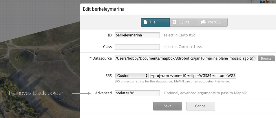
  • To remove the black border from around the imagery, set nodata=0. Usually this value is 0 but the value can vary and can be checked in QGIS
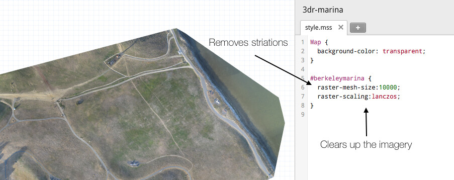
  • Increase the raster -mesh-size. This will make sure reprojection artifacts do not appear
  • Set map-background:transparent. This will make the map look better when overlayed on other imagery
  • Set raster-scaling:lanczos;. This will ensure your imagery is nice and clear. It will also increase your processing time, but it’s worth it.

Once all TileMill parameters are set, upload the imagery to Mapbox.com by clicking Export —> Upload.

Final Result on top of Mapbox Satellite once uploaded to Mapbox.com and styled with mapbox.js.

Sharing the map

Once uploaded to Mapbox.com, you can optionally combine the imagery with Mapbox Streets, Mapbox Satellite or any other layer you have uploaded previously. From there it is easy to share the map either by its URL or as a Youtube-like embed code. To extend the map further use mapbox.js. For instance, the example above is a simple time line built with mapbox.js.

If you have any questions around creating maps from drone imagery or if you would like to share results of your recent flights, hit me up on Twitter @bobws.

Read more…
Moderator


3689584979?profile=original

Top Layer on pc signal in indoor condition

10003964_10203677301477059_1820218844_n.jpg First prototype bottom layer

999966_10203677300677039_1272431247_n.jpg

Signal in outdoor condition

487442_10203677301037048_712883572_n.jpg


Position of satellite.

VR GPS Ublox Lea 6H with HMC5983 Magnetometer


First Virtualrobotix GPS engine using Ublox LEA-6H receiver.

This is a 50-channel high sensitive engine that boasts a Time-To-First-Fix (TTFF) of less than 1 second.

Also provide a rechargeable backup battery to improve warm start.

The dedicated acquisition engine, with over 2 million correlators, is capable of massive parallel time/frequency space searches, enabling it to find satellites instantly.

Innovative design and technology suppresses interference sources and mitigates multipath effects, giving LEA-6H GPS receivers excellent navigation performance even in the most challenging environments.

We are testing also new module NEO 7 and NEO M8 for evaluate how is better module for our drone.

Virtualrobotix GPS uses an high efficient low noise amplifier to improve antenna signal (19dB) and a SAW filter to select GPS frequencies (see graph below).

3689584848?profile=original

In our test we are test different kind of saw filter for improve the quality of gps in presence of RF noise from cpu of other device as Action Camera , in our test for example GOPRO Hero 3+ RF emission is very high and is important to have a good filter for limit the gps glitch.

It also mounting an ultimate 3-axis digital compass, with selectable interface SPI or I2C (HMC5983).

This one is an high speed (220Hz output) and high resolution (2 milli-gauss) magnetometer.


Features and Specifications:

  • ublox LEA-6H module

  • 3,3V or 5V Inputs, with low noise 3.3V regulator.

  • 5 Hz update rate

  • Rechargeable 3V lithium backup battery for high efficient warm start

  • Panasonic Low Noise Amplifier for antenna signal with high gain (19dB)

  • EPCOS SAW high quality low-loss RF filter for GPS application

  • 25 x 25 x 4 mm ceramic patch antenna

  • Dedicated I2C EEPROM for receiver configuration storage

  • High resolution compass (2 milli-gauss) and high speed (2 milli-gauss)

  • Power and fix indicator LEDs

  • ArduPilot Mega compatible 6-pin JST connector

  • Exposed pads for simple soldering connection.

  • I2c / SPI HMC5983 magnetometer .
  • 2 ttl tx-rx ser connection.
  • 38 x 38 x 8.5 mm total size, 18 grams.


Some example from log collected in first test VRX GPS is red Line 3DR is blu


3689585001?profile=original


3689585019?profile=original


3689585073?profile=original

The module will be available in may , for more info of pre order contact us at

info@virtualrobotix.com


http://www.virtualrobotix.it/index.php/en/shop/accessories/3dr-gps-ublox-lea-6-30-37-detail


Origina blog post :

http://www.virtualrobotix.com/profiles/blogs/vr-gps-ublox-lea-6h-with-hmc5983-is-coming

Read more…

The Science of Successful antenna design

3689584353?profile=original

3689584316?profile=original

As promised, James, Brad and Hughes, and anyone else interested, some info on turnstiles and the methods of antenna matching.

James made the following statement:

I came across this link http://www.fpvmanuals.com/category/manuals/equipment-manauls/antennas/  which explains how to build what they call a turn stile antenna.  Could anyone try and explain why this antenna would work as I had really poor performance with it.  I ended up using a simple cross dipole on the RX side with much better results.

I gave the start of an answer in a long reply which can be found in his post : 433 UHF LRS Antenna "Turn Stile"

Some further questions where asked regarding the methods of match the antenna, and the antenna tuning, so I will try to elaborate. 

First some fundamentals.

When I speak of antenna radiation it also includes the reverse, that is, the antenna 'collecting' radiated energy from the ether. 

Any piece of wire will radiate energy when connected to a source of RF ( Your transmitter or receiver). How WELL it radiates that applied energy  is dependent on only two factors-

  - That the antenna is resonant at the same frequency as the radio signal applied and

  - That the feedpoint of the antenna is matched to the impedance of the attached transmitter energy source.

3689584239?profile=original

Maximum energy tranfer between source and load ( the antenna) occurs ONLY when the load and source impedance's are equal.

How well the antenna radiates that energy in any or all directions, if the above conditions are met, is then only dependent on the antenna design, shape, or style. For example, a simple vertical 1/4 wave radiator will radiate a doughnut shaped pattern, in all direction of the compass, with low energy upwards and downwards, in the direction of the antenna element.

A yagi type antenna, on the other hand, ( such as your vhf or uhf TV antenna) focuses the energy in a single direction, as would a torch. Antenna do not have gain. They focus the energy to a greater or lesser extent, in a direction of design, but do this by robbing energy from other radiating directions - Your torch puts more light out the lens end, with nothing out the rear end. If you remove the reflector from behind the torch bulb, the light is radiated in all directions, omnidirectionally, but is much weaker at any distant point than the focused beam.

3689584359?profile=original

Antenna radiation is polarized; that is to say, the radiated electromagnetic wave has a net polarization plane. This is usually either linear or circular. Elliptical polarization is also found, but that is merely a mix of the two former types.

A 1/4wave vertical antenna will radiate linearly, with vertical polarization. Placed on its side it will radiate horizontal polarization.  A Helical antenna ( looks like a coil of wire wound in a screw fashion) wound clockwise when viewed from behind will radiate clockwise circular polarization, and vise versa.

For reception of maximum energy, the two antenna must be identically polarized. There is a massive loss of signal ( easily some 30dB, although the theoretical loss is infinite) if one attempts to receive a horizontally polarized signal with a vertically polarized antenna. Similarly, there are massive losses if trying to receive a circularly polarized signal with an antenna of the opposite circular sense.

The odd man out is that there is only a 3db loss between an antenna that is circularly polarized and one that is linear.

Why would one use circular polarization?

If the two antenna in question could not be made to maintain similar attitudes, such as one in a pitching , rolling aircraft, then there would be unacceptable signal losses as the aircraft banks and pitches. So you could use a vertical on the aircraft, and a helical or turnstile, or similar, on the ground segment. This way you would only ever experience a 3db maximum loss. ( all assuming good line of sight view). Or you could gain back the 3db loss by fitting a similar circularly polarized antenna on the aircraft, giving the best of both worlds. But you actually gain more than that with circular polarization at both ends.

Assume first that the two antenna are simple vertical monopoles, radiating vertically polarized signals. When you are flying, at the flying club, etc, you are probably near some metal structures, the 'hanger' , cars and other vehicles, etc. All these structures reflect the same energy you are trying to receive. In addition, when the aircraft is low and far, the RF transmitted by the A/C antenna follows two paths to your receiver - one directly, and one via a reflection from the ground, somewhat midway between you and the A/C.  What happens to the reflected wave is that the polarization is changed in unpredictable ways. Your receiver ( and antenna) does not know or care where the received energy comes from, so it receives this reflected energy as well. These multitude of received waves add constructively and destructively with the main received wave, causing large, short duration, signal drop-outs - a sort of 'flutter' in the signal.

If both antenna are circularly polarized, however, the picture is quite different. When the circular polarized waveform is reflected , it REVERSES its polarization. When this reversed polarized signal arrives at your receiving antenna it is largely rejected and hugely attenuated, so interfering minimally with the main received signal.

3689584326?profile=original

3689584407?profile=original

On to Issues of resonance and matching.

To repeat a little in my post to James:

Most simple linear antenna are either of the monopole or dipole form. A single monopole ( 1/4 wave vertical for example) or a single dipole will only radiate linear polarization.

Any antenna is only resonant when it is exactly the correct length AT the frequency of operation.( this does not apply to the class of broadband antenna, such as helical antenna, etc. The helical will easily cover an ocatve with good performance).

At resonance the antenna will exhibit its characteristic feedpoint impedance. Feedpoint impedance is expressed with two terms, the pure resistive part, and the reactive ( j operator) part.

Most transmitters and receivers terminal impedance are made to be 50ohms resistive, or very close to that. So it stands to reason the antenna must also be 50ohm resistive to have max energy transfer.  However, none of the antenna are that obliging, so we have to do some feedpoint matching to meet the criteria.

A 1/4wave vertical monopole over a ground plane has a resistive feed point of around 75ohms. A half wave dipole is around 72ohms. As with resistors, placing two dipole in parallel as in the IBcrazy turnstile, will result in a feedpoint impedance of 35ohms.

A 75ohm feed connected to a 50ohm coax and transmitter will exhibit a 1.5:1 SWR ( the ratio of power going out to power reflected). A 1.5:1 SWR means that approx 3% of your transmitter power is not being radiated. ( 30milliwatts for a 1watt transmitter). That is not so bad, and we can live with an SWR of 1.5:1 in most cases.

The turnstile antenna is a pair of crossed dipoles, fed 90deg out of phase with each other, thereby generating circular polarisation. You CANNOT simply connect the dipole in parallel at the coax feedpoint though. Apart from the halving of impedance ( which we decided we can live with) the radiation pattern and polarization of the antenna will be totally destroyed by unwanted radiation from the coax cable. The RF energy, at the dipole connection point, 'leaks' out and currents then flow down the outer shield of the coax. As mentioned previously, any piece of wire will radiate RF energy, and so the coax radiates this energy, and the radiation again adds constructively and destructively with the main antenna radiation, causes complete distortion and signal nulls in the pattern. This radiation from the coax MUST be prevented.

This is done by means of a Balun transformer. - which is is an acronym for 'Balanced to Unbalanced transformer'.

A dipole is a balanced device - it is electrical equal along each element, outwards from the feedpoint. It therefore requires that the feedpoint be fed in a balanced fashion. Coax cable is an an balanced feeder - the shield is at ground potential, while the inner core carries the energy. This effectively ( oversimplifying a little) connects the one dipole half to the 'live' core, and the other half to 'ground' unbalancing the dipole. This causes currents to flow on the coax outer shield, and distortion of the dipole radiation pattern.

Baluns can be constructed from coax cable, but the accuracy required in coax cable length ( they are normally length multiples of 1/4 wavelength) is very critical, especially in the GHz range - 0.5mm can have a great effect.

The turnstile is not new - it is some 50 to 60 years old, and is well researched and published. Up to the VHF and lower UHF region , the coax balun, with embedded impedance match transmission line transformer, is used, along these lines:

3689584418?profile=original

For the higher microwave frequencies, a plumbing type version is more appropriate. This is called the spilt tube or split sheath balun, and looks like this when used as a feed for a pair of crossed dipoles.

3689584368?profile=original

3689584345?profile=original

The balun and feed match consists of an outer and an inner tube. The ration of diameters D/d is chosen to give the desired impedance:

D/d = 1.86 for 75ohms, and 1.5 for 50 ohms.

Typically the outer tube would be around 8mm for use at 2.4GHz.

In order to obtain circular polarisation, I mentioned that the two dipole have to be fed 90deg apart ( phase quadrature).

This can be done as in the coax balun version above ( inserting an extra 1/4wave length of coax in the leg to one dipole gives an extra electrical wavelegnth of 90 degerees). 

Or, this can be achieved by slightly lengthening the one element ( becomes more inductive) and shortening the other( becomes more capacitive) - this also introduces the required phase difference between the elements.

This can be seen in the images above - the one element is typically around 0.21 wavelength per half, while the other is around 0.25 wavelength. One short and one long element penetrate the outer tube and are connected to the inner tube, while the opposite pair of elements are connected only to the outer tube. The outer tube is split or slotted ( 0.5mm width slot). The slot is approx 0.23 wavelength long.

3689584431?profile=original

3689584389?profile=original

The relationship in length between the two dipoles is critical, typically this would be measured on a network analyser and the feed impedance of each element set to say R+j45 ohms ( longer dipole) and the other to R-j45 ohms. This will give the correct phase relationship between elements. A half mm variation can have a great effect, turning a good antenna into a mediocre one..

The last image above shows a teflon tube - this is inserted in the tube from below, and fits snugly inside the outer tube, and over the inner tube. This is then slid up and down to adjust the 'R' part of R+-jX, till the match is a good 50ohms. This does not affect the antenna radiation pattern or characteristics. Obtaining a 50ohm impedance match can be done by trimming the element lengths as well, at the same time destroying the antenna radiation pattern and circularity.

And that is why it is not so simple to do at home, and why the 'Hobby King'  et al variants sold everywhere are mostly trash..You will probably achieve a few km range with those- remember, any old piece of wire will radiate -  I easily  achieve 15km with 500milliwats at 2.4GHz using two split sheath balun , properly matched and trimmed, crossed dipoles..

For those interested:

References are - RSGB VHF/UHF Manual - page 8.45

Modern Antenna Design - Page 255

Here are some images of my split sheath balun crossed dipoles..

3689584470?profile=original

3689584445?profile=original

Joe

The Nampilot.

Read more…

3689584952?profile=original

CAA to hit illegal drone flyers with hefty fines


Johannesburg - The South African Civil Aviation Authority (SACAA) is set to clamp down on the illegal flying of Unmanned Aircraft Systems (UAS), or drones, in civil airspace.

According to a statement sent out by SACAA, the move was prompted by recent reports of UAS already operating in the South African civil aviation airspace.   

UAS are classified as any aircraft that can fly without a pilot on board. They come in all sorts of shapes and sizes and can be controlled remotely by an individual on the ground, in another aircraft or through an on board computer system.    

Current civil aviation legislation does not provide for certification, registration and/or operation of UAS in the South African civil aviation airspace. 

"The fact is that the SACAA has not given any concession or approval to any organisation, individual, institution or government entity to operate UAS within the civil aviation airspace. Those that are flying any type of unmanned aircraft are doing so illegally; and as the regulator we cannot condone any form of blatant disregard of applicable rules,” said Poppy Khoza, Director of Civil Aviation. 

While this was hardly problematic before, a surge in demand for the use of drones - especially for commercial purposes - has prompted the SACAA to integrate the use of drones into the South Africa airspace as speedily as possible.    

In the mean time, until regulations have been put in place, anyone caught operating a UAS could face fines of up to R50 000, a prison sentence of up to 10 years or both. 

The use of GoPro drones have proven to be particularly useful in the creation of video and photographic content for publications. The bird's eye footage not only provides alternative, fresh views of events and happenings, but also allows media access to crowded or inaccessible areas.

A recent example includes drones being sent up to gain unprecedented footage of the opening of the Oscar Pistorius trial at the North Gauteng High Court in Pretoria.

In June last year police officers apprehended a man who flew a radio-controlled mini helicopterover the Pretoria hospital, where former president Nelson Mandela was being treated.

Less controversially, drones can also be used to capture incredible never-seen-before natural imagery, such as this thousand-strong dolphin pod migration. 

As the regulator of civil aviation safety and security, the SACAA has noted the need to put regulations in place to deal specifically with UAVs.     

“Unmanned aircraft systems are a relatively new component of the civil aviation framework, one which the SACAA, together with other regulators worldwide and under the guidance of the International Civil Aviation Organisation (ICAO), are working to understand, define and ultimately integrate in to the civil aviation sector. As such, the process of developing policies, procedures, regulations and associated standards in order to certify and subsequently authorise operation of UAS is currently in progress,” Khoza explained.  

In collaboration with other ICAO member states, South Africa is working towards providing a regulatory framework and guidance material, to underpin routine operation of UAS in a safe, harmonised and seamless manner comparable to that of manned operations.   

There are many factors to consider in the process of developing guidelines for authorisation, but the SACAA are targeting the end of the second quarter of this financial year to have some guideline document that could be followed. 

“The SACAA acknowledges that the current civil aviation legislation does not provide for certification, registration and/or operation of UAS in the South African civil aviation airspace. We are also cognizant of the urgent need and demand for UAS usage for commercial and many other reasons. Hence, the SACAA has allocated the necessary resources to the UAS programme to ensure a speedy integration of drones into the South Africa airspace. However, until then we would like to appeal to those that are disregarding the laws to desist from such actions,” Khoza concluded.  


http://www.news24.com/Travel/Flights/CAA-to-crackdown-on-illegal-drone-flights-20140402

Read more…

Video showing how to use UGCS in action

3689584931?profile=original

We have created video showing UGCS in action. There are series of videos explaining different aspects and features of UGCS mission planning software. There is even video showing how to connect copters to UGCS and actual footage of simple group flight and telemetry.

Videos on UGCS usage can be found here: https://www.youtube.com/playlist?list=PLRfRuRLHgAaWRJLLbUY7OUJg0LwZEKgtJ

Please know that UGCS is available for free just by registering at our site www.ugcs.com. For free version we provide support right here at DIYDrones.com. Look up the UGCS users group http://diydrones.com/group/ugcs

Now here is challenge. Who will be the one operating most drones simultaneously using UGCS! Get your copters together and try it! :)

Read more…

Fukushima photo essay by Drone Adventures

3689584818?profile=original

Drone Adventures teamed up with Taichi Furuhashi, researcher at the Center for Spatial Information Science at the University of Tokyo and mapped three unique towns in Fukushima district: Iidate village, Hisanohama, and Tomioka.

Read more below about the details of this project and don't forget to look at the high-resolution interactive maps created by Drone Adventures:

http://robohub.org/fukushima-photo-essay-a-drones-eye-view/

Read more…

3689584863?profile=original

http://www.dailymail.co.uk/sciencetech/article-2595245/First-UK-prosecution-dangerous-driving-DRONE-Man-fined-800-illegal-flying-unmanned-aircraft.html

First ever UK prosecution for dangerous driving of a DRONE: Man fined £800 for illegal flying of unmanned aircraft

  • Robert Knowles, 46, was found to have flown his homemade aircraft into restricted airspace over a nuclear submarine facility
  • He also flew his drone, which was equipped with a video camera, too close to a vehicle bridge in an illegal manoeuvre
  • Both offences breached the UK’s Air Navigation Order and he was found guilty on April 1 and fined £800 at Furness and District Magistrate Court
  • The UK Civil Aviation Authority (CAA) said the conviction sends a message to recreational users of drones that they are subject to aviation safety rules

A man has become the first person in Britain to be successfully prosecuted for the dangerous and illegal flying of an unmanned aircraft (UAV).

Robert Knowles, 46, was found to have flown his homemade aircraft into restricted airspace over a nuclear submarine facility, as well as flying the drone too close to a vehicle bridge.

Both offences breached the UK’s Air Navigation Order.

Beware incoming: A man from Cumbria has become the first person in the UK to be successfully prosecuted for the dangerous and illegal flying of an unmanned aircraft (UAV). A stock image of a quadcopter drone is pictured, but Robert Knowles' UAV was homemade

Beware incoming: A man from Cumbria has become the first person in the UK to be successfully prosecuted for the dangerous and illegal flying of an unmanned aircraft (UAV). A stock image of a quadcopter drone is pictured, but Robert Knowles' UAV was homemade

Mr Knowles, of Barrow-in-Furness, Cumbria, was found guilty on 1 April and fined £800 at Furness and District Magistrate Court following the prosecution by the UK Civil Aviation Authority (CAA), who said the case raised important safety issues concerning recreational flying of unmanned aircraft.

THE CAA’S RULES FOR OPERATING UAVS WITHIN THE LAW

  • A drone must never be flown beyond the normal unaided ‘line of sight’ of the person operating it. This is generally measured as 1,640ft (500m) horizontally or 400ft (121m) vertically.
  • A UAV fitted with a camera must always be flown at least 164ft (50m) distance away from a person, vehicle, building or structure.
  • A UAV fitted with a camera must not be flown within 492ft (150metres) of a congested area or large group of people, such as a sporting event or concert.
  • Consideration must be shown to other airspace users. Therefore unmanned aircraft should not be used in the vicinity of airports or within restricted airspace.

The court heard that on 25 August, a UAV was recovered from water near to a submarine testing facility in Barrow-in-Furness, operated by the defence company, BAE Systems.


The aircraft is said to have flown through restricted airspace around the nuclear submarine facility before it crashed.

A spokesman for the CAA told MailOnline that the UAV was more like a model airplane than a helicopter-style aircraft and was built from scratch, with a small video camera attached to its body.

The police were called to investigate whether the video footage was a security concern and while they decided the flight was not a significant security breach, analysis of the video footage taken from a camera fitted to the device subsequently revealed that during its flight the drone had skimmed over the busy Jubilee Bridge over Walney Channel.

The UAC was well within the legally permitted 164ft (50metres) separation distance required, according to the CAA.

After it was recovered, the UAV was traced to Mr Knowles who admitted to building the device himself and operating it on the day in question.

He was charged with flying a small unmanned surveillance aircraft within 164ft (50metres) of a structure and flying over a nuclear installation.

The CAA said the conviction sent a message to recreational users of UAVs that the devices are subject to aviation safety rules.

Punished: Mr Knowles, of Barrow-in-Furness, was found guilty on April 1 and fined £800 at Furness and District Magistrate Court. The court heard that on August 25, a UAV was recovered from water near to a submarine testing facility in Barrow-in-Furness (pictured) operated by the defence company, BAE Systems

Punished: Mr Knowles, of Barrow-in-Furness, was found guilty on April 1 and fined £800 at Furness and District Magistrate Court. The court heard that on August 25, a UAV was recovered from water near to a submarine testing facility in Barrow-in-Furness (pictured) operated by the defence company, BAE Systems

A spokesman for the authority said: ‘Anyone operating an unmanned aircraft for their own private use should be aware that they have to abide by certain rules.

'These rules are in place to protect the safety of the public, and simply require operators to maintain a safe set distance between their unmanned aircraft and any people, buildings or vehicles in the vicinity. Followed correctly, these rules will not interfere with the ability of an individual to fly an unmanned aircraft recreationally.’

The conviction of Robert Knowles follows the recent case of a photographer from Lancashire accepting a caution for using a UAV for commercial gain without permission.

Lawrence Clift had sold footage of a school fire taken from his quadcopter to media organisations, even though he did not have authority from the CAA to operate the device commercially.

Anyone using unmanned aircraft for ‘aerial work’ requires special permission from the CAA, which the body claims ensures safety standards are being adhered to and that the operator  of the UAV is fully insured.

Found: The drone was reportedly found crashed in water near to BAE Systems' submarines testing facility in Barrow-in-Furness (pictured). After it was recovered, the UAV was traced to Mr Knowles who admitted to building the device himself and operating it on the day in question

Found: The drone was reportedly found crashed in water near to BAE Systems' submarines testing facility in Barrow-in-Furness (pictured). After it was recovered, the UAV was traced to Mr Knowles who admitted to building the device himself and operating it on the day in question

Read more…

3689584519?profile=originalWe did a quick evaluation how much accuracy we could achieve on all axises using a multirotor. We read many accuracy reports from fixed wings and this teaches us that the planimetric accuracy (horizontal) is usually about 1x the ground sampling distance (GSD) (0.5 if you're really good and have better cameras) and that the vertical accuracy (Z) is usually 2-3 times the horizontal accuracy. That's only valid for some altitude ranges, the regular flight altitude for uav's between 80-150 meters. Forward velocity and trigger distance requires a certain altitude to make it work.

Here we lowered the altitude from 80m to 40m and used a multirotor. We wanted to find out whether the vertical accuracy definitely would improve and hopefully establish a 1:1 relationship between vertical accuracy and GSD as well. The reason why vertical accuracy would improve steadily is because there's more perspective in images at lower altitude, so you pick up more height information in each image, which corresponds to better Z estimates.

In this example case we flew at 45 meters with a hexa at a speed of 3 m/s to get a high 85% forward overlap, making it more difficult for a wing to do the same. 211 photos were taken. The GSD produced is 1.41cm.

The photos were georeferenced using 5 marker points that were collected with high precision GPS equipment. The expectation is that when these GCP's are marked in the image, there's about a 0.5-1 pixel deviation, so it's expected that the error in marking GCP's is about 0,5-1 GSD as well. Sharper pictures and better markers reduce that error.

In this case we had 2 less accurate GCP's, so the planimetric accuracy of this dataset eventually became 1.7cm, slightly above 1* GSD. What we confirmed though is that we got a 1.8cm vertical accuracy for this set, (or rather, the residual error from the mathematical model).

This dataset could have been improved as follows:

  • Better marking of GCP's and more attention paid during GCP marking.
  • Sharper photos (better lenses).
  • Higher precision GPS.

In the end, the maximum accuracy that one should expect with this equipment is 1* the GSD and better equipment isn't going to make this magically happen. This accuracy isn't correlated to the real world, that would be a totally different exercise altogether.

Here are some detailed images of the point cloud from close up. Notice the vertical detail of the irregular curb.

3689584560?profile=originalAnd the detail of a house. The planar surfaces aren't warped, a good indication of excellent georeferencing and accurate point triangulation.

3689584540?profile=originalThis experiment is very relevant, because Lidar is commonly used for "real" precision projects, often considered for work where they need better than x cm precision. Although lidar data is probably as accurate as 5mm, it is also subject to occlusions and the station needs to be moved around a lot to get proper point cloud coverage, so operating it isn't all that easy.

UAV point clouds may always have less accuracy than laser clouds, but they do have the advantage of the bird's eye view: they generate data across an entire region with the same consistency in accuracy and density, whereas lidar isn't that consistently dense for every part of the survey area due to occlusions.

Price makes a big difference too. Lidar stations apparently cost $175k to acquire, whereas uav's probably put you back by $3000. The question that one needs to answer is whether the slight improvement in accuracy is worth the extra money.

What this experiment shows is that also for uav's 2cm vertical accuracy is probably within the possibilities, pending further experiments where datasets are compared against points in the real world.

Read more…

Welcome to the Humanitarian UAV Network

UAViators Logo

The Humanitarian UAV Network (UAViators) is now live. Click here to access and join the network. Advisors include representatives from 3D Robotics, AirDroids, senseFly & DroneAdventures, OpenRelief, ShadowView Foundation, ICT4Peace Foundation, the United Nations and more. The website provides a unique set of resources, including the most comprehensive case study of humanitarian UAV deployments, a directory of organizations engaged in the humanitarian UAV space and a detailed list of references to keep track of ongoing research in this rapidly evolving area. All of these documents along with the network's Code of Conduct—the only one of it's kind—are easily accessible here.

UAViators 4 Teams

The UAViators website also includes 8 action-oriented Teams, four of which are displayed above. The Flight Team, for example, includes both new and highly experienced UAV pilots while the Imagery Team comprises members interested in imagery analysis. Other teams include the Camera, Legal and Policy Teams. In addition to this Team page, the site also has a dedicated Operations page to facilitate & coordinate safe and responsible UAV deployments in support of humanitarian efforts. In between deployments, the website's Global Forum is a place where members share information about relevant news, events and more. One such event, for example, is the upcoming Drone/UAV Search & Rescue Challenge that UAViators is sponsoring.

When first announcing this initiative,  I duly noted that launching such a network will at first raise more questions than answers, but I welcome the challenge and believe that members of UAViators are well placed to facilitate the safe and responsible use of UAVs in a variety of humanitarian contexts.

Acknowledgements: Many thanks to colleagues and members of the Advisory Board who provided invaluable feedback and guidance in the lead-up to this launch. The Humanitarian UAV Network is result of collective vision and effort.

See also:

  • How UAVs are Making a Difference in Disaster Response [link]
  • Humanitarians Using UAVs for Post Disaster Recovery [link]
  • Grassroots UAVs for Disaster Response [link]
  • Using UAVs for Search & Rescue [link]
  • Crowdsourcing Analysis of UAV Imagery for Search and Rescue [link]
Read more…

April Fool's joke made real

We joked about using FPV gear to try 3rd person snowboarding last April 1st.  And then we made it happen!

3rd person RC flying: old hat.
1st person RC flying: cool! but done.
1st person snowboarding: fun! and done.
3rd person snowboarding: at long last.

Finally, this 4th quadrant is filled-in. I tried it so you don't have to! Watch the video to see how it went.


Maybe next season we'll try again with an autonomous follow-copter as the camera platform!

Read more…

UAV flying over Lithuania

This is little video which I put together last summer before UAV competition (Our team won 1st place!).

Competition consisted 3 main tasks:

1.Reading information from horizontal target (known place)

2.Reading information from vertical target (known place)

3.Finding target in known area


Our team almost succeeded in main 3 tasks (we found target but camera got it on edge of screen and wasn't really clear)


Setup: DragonFly-1 platform

APM 2.5 from RCtimer with 2.74 ArduPlane

HD Wing Camera II 1080P


Thanks Ministry of Economy of the Republic of Lithuania for sponsoring competition.


Read more…

Hi guys,

I recently bought Pixhak AP and finally calibrated it on TBS Disco. It fly's really stable and reliable. The Twinstar is flying with APM 2.5 and same thing here, 6km fpv is a pure plesure.

Also wanted to show you our designated spot for drone flying and testing in Warsaw, Poland. Do you have a place where officials let you fly your drones? You hear a lot about restrictions in U.S and other countries. I wonder how is it in your place of living?


Best to All,

Greg


Read more…
Developer

3689583965?profile=original

We now have a new update to APM Planner. The major achievement is we now have prebuilt linux builds avaiable for debian and Ubuntu flavours.

See http://ardupilot.com/downloads/?category=35

Functional features include log downloading over MAVLink (no need to go to the Terminal anymore) and .bin dataflash log file support. So if you have large files on an SD card you can just put the card in your computer and copy them before analysis.

There's also numerous bug fixes, thanks to all who have raised these issues to our attention.

Thanks,

AP2 Team.

Raise support requests here http://ardupilot.com/forum/viewforum.php?f=82
Read more…
Moderator

3689583787?profile=original

3689583853?profile=original

This is the final configuration of VR Tiger Shark X8  RTF  :

The drone is designed and produced in our lab . The material use in Tiger Shark are Carbon Fiber and ergal . The plastic cover and finiture make by 3D printing  SLS technology.


VR Brain is the Autopilot board used in Tiger Shark.

VR Gimbal is the Brushless gimbal controller in Easy Shot Gimbal .


Between Tiger Shark and Easy shot we put a special anti vibration system that cut vibration from drone frame to gimbal. After a lot of work for setup it work very well :)


The frame configuration is X8 coaxial configuration we choose to use this configuration because is possible continue to fly also without two propeller if the payload is not so heavy .


The Payload for camera is near 1 kg . With a 10 Amp 4S battery we are near 15 min of fight.


This is a last fly test doing by Emile with Tiger Shark and Easy Shot Gimbal.

The fly test is doing with last revision of APM Copter available on our repository :

http://vrbrain.wordpress.com/download/version-3-0/

This is the revision of code use on VR Gimbal 

http://vrgimbal.wordpress.com/download/vrgimbal-1-13-2/


The Fly of drone is very smoth and automatic functionality as loiter are solid as rock.


Original blog post : http://www.virtualrobotix.com/profiles/blogs/vr-tiger-shark-x8-vr-gimbal-fly-test-doing-by-emile-last-week

Read more…