Get a head start on the NASA Centennial Challenge's ADS-B requirements by plugging a $20 USB dongle into your drone and tracking nearby aircraft:
Start with an AR.Drone (or other ARM-based amateur drone).
Buy a $30 USB dongle. See the rtl-sdr wiki for recommendations.
Compile and install the dump1090 Mode S/ADS-B decoder software with my easy-to-use cross-compiler setup: ardrone-dump1090-cross-compiler
Plug in the receiver.
And now you're decoding packets:
ADS-B sense-and-avoid is seen as critical to integrating unmanned aircraft into the National Air Space, and this is the beginning of a cheap "sense" solution. Next up: "avoid".
Posted by Alan Sanchez on April 2, 2013 at 10:27am
We are still growing fast at 3D Robotics. We are looking to expand our engineering team here in San Diego and are looking for a Mechanical Engineer to join us. You can see our other job listings at the company blog here.
Mechanical Engineer
Responsibilities
You will be responsible for contributing to the design, development, manufacturing and testing of new products for 3D Robotics. You will use your engineering expertise and design thinking to create functional and aesthetically pleasing products while working as an integral member of a multi-disciplinary team at 3D Robotics. You will engage with manufacturers, vendors and partners as you work on the development of new products. Because of the wide variety of products we design you will likely design for a wide variety of manufacturing processes (injection molding, metal extrusion, CNC milling, composite fabrication, etc)
Qualifications
BS in Mechanical/Aerospace Engineering or equivalent.
Minimum of 2 years of relevant working experience.
Proficiency in CAD solid modeling and finite element analysis. (Proficiency in Autodesk Inventor is a plus)
Mechanical Design experience.
Product development and manufacturing experience.
Attention to detail and commitment to quality.
Capable of working in a multidisciplinary team environment.
Excellent verbal and written communication skills.
Computer proficiency.
Electrical and electronics experience is a plus.
Familiarity with 3D Robotics products is a plus.
How to apply
Please submit your cover letter, resume, portfolio and any additional material to jobs@3drobotics.com.
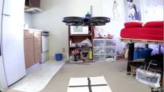
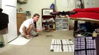
The copter flies away & returns to the starting point at 2 different altitudes, using only optical flow odometry for position & sonar for altitude. The fact that it landed at nearly the takeoff position was probably coincidence, but optical flow has proven very accurate in a 30 second hover. It may depend more on time than movement.
For the 1st time in many years, the entire autopilot was on board. Only configuration parameters are still stored on the ground station.
The takeoff is hard coded for a certain battery charge. This battery may have put out a lot more than the battery it was hard coded for, causing it to bounce during the takeoff. Nothing optical flow guided besides the AR Drone has been shown doing autonomous takeoffs & landings. It takes a lot of magic.
It was a lot more stable than the ground based camera. Ground based vision had a hard time seeing the angle of movement, relative to the copter. Optical flow has precise X & Y detection in copter frame.
How long can they stay in bounds? The mini AR Drone did surprisingly well, compared to the commercially successful AR Drone. The degradation was reasonable for a camera with 1/3 the resolution & 2/3 the frame rate. It's not likely to get more accurate. The mane problem is glitches in the Maxbotix.
Optical flow can hover for around 90 seconds at 0.5m before slipping off the floor pattern. Above 1m, it slips off after 1 minute. At 1.5m, it slips off after 30 seconds. The Maxbotix falls apart at 1.5m over posterboard.
The mane requirement in optical flow is the angular motion needs to be very accurately eliminated or it won't work at all. Using the IMU gyros works well. This is done by adjusting a 2nd pair of gyro scale values until rotating the camera doesn't produce a position change.
The heading & altitude need to be factored in when integrating optical flow or it won't accurately calculate position. The academic way to convert pixels to ground distance involves a tan of the pixel shift to compensate for parallax, then multiply by the altitude. The pixels are so small, the parallax was neglected & the pixel shift was just multiplied by altitude.
Optical flow initially needs to be tested on something like this:
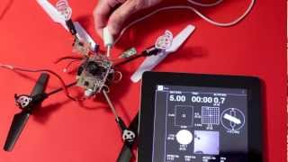
To gain enough confidence & calibrate it enough to start integrating it on this:
A lot of energy went into finding the optimum floor pattern.
So the optimum pattern seems to be random splotches of paint with dry brushing in a grid. Too much brushing makes it too smooth. A few gallons of toner would be nice. A laser printer could get the optimum fractal pattern perfect.
For all the energy going into making robots navigate human environments, there's no pondering of the idea of making human environments navigable for robots. Floors with optical flow patterns would be a lot easier than LIDAR.
Straight lines of featureless tape were the worst. It seems to rely on texture of the paint up close, while painted patterns far away. The only way to get a pattern big enough to fill the flying area with enough reflection for sonar is paint on a plastic drop cloth.
The worst patterns require a higher minimum motion. The best patterns cause the least minimum motion to be detected. The pattern affects the outcome more than the frame rate or resolution.
Long & boring video documenting interference between wifi & the Maxbotix MB1043, the world's most temperamental sensor. Some orientations do better than others. The Maxbotix & wifi wouldn't be very useful on any smaller vehicle.
A totally random orientation of wire & dongle was required. Wire orientation, wire insulation, dongle orientation, dongle distance all determined whether the Maxbotix died. Any slight movement of the wire breaks it.
The automatic takeoff & altitude hold were extremely accurate. The 10Hz update rate wasn't as problematic as feared.
So basically, after 6 years, the Maxbotix still has to be powered up facing away from the ground or it returns bogus values. This continues to be the greatest scourge of sonar navigation. The Parallax sensor in the AR Drone initializes properly with no clearance.
It still needs an external RC filter to filter the power supply. You'd think they would have found a way to store the calibration data on the flash or make a bigger board with integrated power filter to generate the best readings.
The Maxbotix still requires a manual trigger to range at its maximum rate of 10Hz, but it repeats the same value if triggered at less than 25Hz. It needs to be triggered at 50Hz to output 10Hz of unique data.
Flying it manually with the tablet is reasonably easy.
The mini AR Drone has an MPU9150 read at 1100Hz for the gyros, 125Hz for the accelerometers & mag. The PWM is 2000Hz. The IMU needs liberal foam padding or the attitude readout drifts too fast.
It turns out USB host on the STM32F407 interferes with I2C, so you can't read the IMU when wifi is on. It has nothing to do with RF interference. The IMU has to be driven off a secondary microprocessor & the data forwarded on a UART. It needed a 400khz UART to transfer the readings fast enough.
There's at least 0.5ms of extra delay to get the readings from the I2C breakout processor to the mane processor. The I2C interface itself has at least 0.4ms of delay to get the voltage from the gyro. In total, it could take 1ms for a motion to be detected. Such is the sacrifice of reading out an IMU on I2C. The delays from movement to digital reading are what make instability. It's not unlike the AR Drone, which has a second microprocessor read the I2C sensors.
The electronics with wifi use 300mA. Wifi sends 2 megabits, manely consisting of the optical flow preview video. Star grounding & star power supply were required for anything to work. Having everything except the motors behind a 3.3V regulator & 1000uF of capacitance was required.
Wifi was especially sensitive to voltage glitches, making running on a 4.2V battery with lousy MIC5205 regulators extra hard. The MIC5353 would be a much better experience.
After years of dicking around with charge pumps, pullup resistors, & BJT's to turn on MOSFETs that require 5V to turn on, finally got around to probing the Syma X1's board. It uses a MOSFET that turns on at 2.5V, the 9926A. The 9926A is an extremely popular dual MOSFET made by many manufacturers.
The electronics weigh around the same as a PX4Flow, except using the PX4Flow would have required another board in addition to it. The PX4flow was ruled out because of the weight & the size being too big to fit anywhere.
PX4Flow weight: 17.5g
With the PX4Flow connected to USB & Qgroundcontrol fired up on a Mac, it was immediately clear that it had a very long, sharp, macro lens, allowing it to resolve texture from far away.
Setting it to low light mode produced a noisier image. In any mode, the position updates came in at 100Hz, despite the sensor capturing 200Hz.
It didn't need any calibration. Just connect it & it outputs Mavlink position packets. The lens was already focused. It outputs packets at 100Hz on USART 3 but not USART2. It seems to run as low as 3.3V at 120mA. Below that, current drops & LEDs start going out. Above that until the 5V maximum, current is constant.
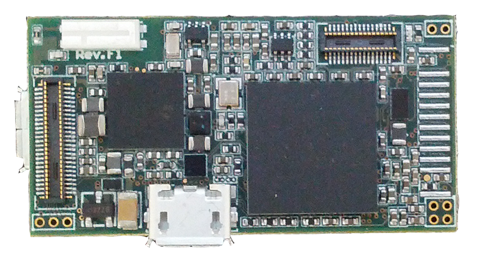
Most of what the PX4Flow does was redone on a new board, with the TCM8230. The autopilot was implemented on the same chip. The optical flow only does single pixel accuracy, 42fps. It crops to get a similar narrow field of view. It scans a 96x96 area instead of the PX4flow's 64x64. The scan radius is 8 pixels instead of the PX4flow's 4.
It requires a more detailed surface than the PX4Flow. The optimum combination of camera contrast, motion distance, frame rate, & scan radius dictated the camera run at 320x240. Running a higher frame rate or resolution made the camera less sensitive & blurrier in the X direction.
Also, the PX4flow uses a histogram of the motion vectors. Found better results from a straight average of the motion vectors.
Assembly language made an incremental improvement in the scanning speed, but the mane limitation still seemed to be memory access. The scanning area & scan radius would probably have to be slightly smaller in C.
The Goog couldn't find any examples of vectored thumb inline assembly, so it was a matter of trial & error. The STM32F4 programming manual, inline assembler cookbook, & STM32 Discovery firmware are your biggest allies in this part of the adventure.
It turns out there are no NEON instructions in thumb mode. Thumb mode has yet another set of vectored instructions with no special name.
For the 1st time ever, it's the inline assembly language absolute difference of an 8x8 macroblock:
Just finished trimming and sanding my newly fabricated landing gear.
As best as I can tell these things are incredibly strong, and as they are made of fiberglass quite shock resistant and incredibly forgiving to sheering force. These are for my 10lb aluminum H style A/V Quad that is almost done. The weight makes the thing incredibly stable with regard to video.The entire process from mold fabrication to final touches took about a day and a half, all that's left is spray painting them, but that should only take a couple of minutes.
Some quick notes:
18 plys that degrade in size at two inches per layer so that the thickest point is at the top where the maximum level of bending potential will be.
(3 full length plys first and last; for finish and delamination protection)
Since people have been talking about building nice shock resistant landing gear on the cheap and quickly I thought I would post my solution; and a tutorial on how to build some of your own.
As you can see the mold can be tailored to make 3 - 4 landing gear at once, and really just depends on how much raw material you end up having.
As of now I hope to have the complete tutorial out by about the fourth, I hope it will help some of you guys out though I realize that most of you are more than familiar with the process.
In yet another example of non-military application of drones, NASA researchers investigate the gases in a volcanic plume in Costa Rica with small electric-powered planes. These planes are, in fact, repurposed military drones being applied to the benefit of mankind.
The full story, with maps, graphics, and more photos is at:
The wind was calmer then it has been in months so I decided to see just how stable the Arducopter (2.5 APM, UBlox GPS) can be with the 2.9.1 code. I was pleased, I could have hovered until the battery runs down. Also, landing while in Loiter is really smooth, much better than I could do flying in stable mode!. Just had flip the switch back to stable mode once down to finish the flight properly.
A Great week for all attendants and a glorious 2day for all DIYDrones members and APM users & Devs!!
With glad, i realized that a great amount of US and EU researchers use APM for their work, combine & exchange knowledge and as a super active community members involve rapidly at their expertizes.
I was one of the lucky who followed the UAS fundamentals workshop, attended all the wonderfull thinks that photogrammetry and remote sensing geniuses were up to and watch what market leaders had to display, as well as presenting our efforts of creating a UAS for precision agriculture!
Special Session: UAS Capabilities Overview, with a great overveiw of the UAS potentuals and a long discussion for there integration at US airspace "system" by FAA. I understud the conserns and problems, but since iam not US citizen, neither fly at, i wont express my opinnion, but i think its usefull to inform you that there is a major consultation with FAA to overcome any issues.
Heres a quick video with our paper presentaion
If you can tolerate gopro's mic and my terrible english here is the full presentation
I want to thank
-Every fellow that i ve met at the conference and encouraged our work, i wish them the best,
-All DIYD members for their support,
And last but not least, my friends and colleagues at UcanDrone Team
If you missed the conference and you were intersted at a topic here is the final program if you want to find somebody.
Posted by Chris Lovett on March 31, 2013 at 3:00pm
Hey, I had to get my roof repaired, and so I took my quad up for a little roof inspection afterwards. Worked great. I reckon you could sell this as a package to roofing companies. That way they could show home owners how bad their roofs are and why they need repair, and then show them how great it looks when all the work is done.
Taulab is a fork of Original Open Pilot project , some guys decide to fork it and develop a code that support a lot of different platform .
The main advantages of this project is that native at 32 bit , use a operating system and all the code is write in pure c , not use c++ class.
A lot more complex of other project but very interesting for developers.
The other advantages of work doing by Stefan is the opportunity to doing some benchmark between two firmware that use same hardware VR Brain .
Could be interesting evaluate the quality and performance of firmware ported to 32 bit platform as Arducopter32 rev 2.9.1.1 and TauLab that instead use an Operating system and is 32 bit native.
This is only a introduction of work doing by Stefan he promise me that create a post with more info about his works :)
So this is some example of how vrbrain fly with TauLab Project firmware
Stable fly :
Simple Fly :
The next step will be : return to home , auto landing and navigation waypoint :)
*** This Group's Main Focus is to Help Assist in Any Way in the Development of the Fighting Walrus Radio for iOS telemetry***
This is a group dedicated to networking and organizing/discussing Group Fly Events in and around the Minneapolis area for all Drone,RC,and UAV Hobbyists!
Useful Links to the Fighting Walrus Dev Group and Blogs
We have a winner! Adrian Mescalchini is the victor of our "Design a New Banner" competition, and his work is now gracing the top of this page. We'll work with him to slightly enlarge the type, but the overall design was a clear favorite amongst those voting in the poll over at Google+ (I wanted to also get the views of a broader community, not just the current members of this site)
Coming in a strong second was Petrus Botha, with this impressive range of options:
It was hard to choose just one, so in recognition of two such talented designers, both will be getting a full APM 2.5 kit as prizes. But Adrian, as the people's choice, wins the top award, of the banner at the top of this page.
Many thanks to all the others who entered this competition. Ning, our hosting platform, is moving to a 3.0 version with a lot of new design tools and a cleaner aesthetic, and we'll be migrating to that this summer. That means lots of additional opportunities for this community to contribute to the evolution of our design. More contests, more prizes!
Meanwhile, Adrian and Petrus, if you're looking for more design work, please ping me. We'd love to sign you up for paid design work at 3DR. Or frankly anywhere else where I can use cool graphics. You both rock!
It's a Bluetooth Low Energy Arduino Compatible platform. It uses a ARM CoreTex-M0 for processing power. It has shields that support servo motors amongst many other options. This would be a great platform for a bridge between a long range radio to your UAV and tablet based GCS. Could easily be programmed to support Antenna tracking, and it's cheap. Being Arduino compatible APIs would allow porting of the ArduStation code.
Bluetooth LE (also know as Bluetooth Smart) is supported on the most popular smartphone and tablets, Samsung S3 has BLE, as well as Apple iDevices. As the world of Internet of Things grows, BLE looks to become a major way to connect to these devices.
I thought I would post some information about some research I have done. This video shows a simulation of UAVs swarming with an advanced control algorithms.
Seven UAVs are shown, which find a source of fumes or aerosols by measuring the concentration at their actual position. Due to communication and a distributed Extended Kalman Filter they estimate the fumes position. These UAVs fly at a certain concentration line, which in the video is marked blue. This is just a demonstartion of one kind of task for the swarm.
The main focus for all of the research is to see what can be accomplished by getting a large group of relatively simple machines to work together. Each device has a microcontroller brain, camera, accelerometer, proximity sensors, and a microphone. By mixing and matching the use of available components they can test different concepts which will be useful in creating utility robot swarms for real-world tasks. The video shows off the robots grouping themselves by like characteristic, a test called segregation (the purpose of this didn’t resonate with us), and group tasks like moving that box. The nice thing is that a series of white papers is available at the post linked above (click on the PDF icon) so that you may dig deeper if these projects are of interest to you.
Earlier this year there was some discussion of the AllwaysInnovating Mecam. Here's some more details, which make the unit very interesting.
The MeCam is based on the Always Innovating Cortex-A9 SoC Module which can run from 1.0GHz to 1.5GHz depending on the configuration. It's the world smallest module available on the market that offers GHz Arm-based CPU, 1GB RAM, SD card, 2.4GHz/5GHz Wi-Fi and Bluetooth connectivity.
It's amazing to see the compute power getting ever cheaper and ever smaller!
There's a really good piece in this week's Business Week (print, web and Ipad, shown) about DIY Drones.
Here's how it begins:
The Federal Aviation Administration isn’t expected to approve unmanned aerial vehicles for commercial use until at least 2015. Even so, manufacturers are already preparing to jump into the market—relying on the open-source movement for free research and development. Amateur designers and manufacturers are building prototypes at home, then e-mailing or posting the results, often with how-tos that can be completed using part-making 3D printers.
That’s giving far more people, including startups, an opening in the $1.6 billion market for drone design, which will almost double in a decade, according to the aerospace and defense consulting firm Teal Group. Online support is “quite a game-changer,” says Jeff Moe, chief executive officer of open-source 3D printer company Aleph Objects. “You have collaborative worldwide development of hardware and electronics.”
The teamwork extends from pilotless aerial vehicles that spray crops or map coral reefs to those that detect radiation. DIY Drones, an online community founded by former Wired Editor-in-Chief Chris Anderson, has more than 35,000 members and provides free access to thousands of schematics. Its pages receive more than 2 million views per month, says Anderson, whose own company, 3D Robotics, is making use of the crowd-sourced R&D. “We’ve been able to bring this huge amount of energy, ideas, and talent to bear for free that otherwise would have taken millions of dollars,” he says, citing his drone autopilot software, radios, video components, and camera controls among the designs he developed with help from DIY.
ArduCopter / ArduRover / ArduPlane specific GPS devices with uBlox NEO6 modules are here...
Finally they are here. We have been testing and developing these GPS devices over 4 months and now they are available on jDrones store. These modules are optimized for ArduCopter and ArduPlane use and we have been having great success with these modules. Accuracy on jDrones Quad/Hexa copters is amazing when using these modules. Position accuracy is close to 1 meter and 3D lock times are counted in seconds.
Model One: is specially made for ArduCopter / Multicopter use and it has detachable high patch antenna with 10cm cable so if you want you can always detach antenna from main module and put it on big groundplane.
Top side of ArduCopter / Multicopter GPS
Bottom side of GPS with antenna detached:
Technical detail:
PCB size 38 x 38 mm
Mounting holes 32 x 32 mm, M3
EM406 style connector
28 x 28mm detachable high gain antenna
Battery backup
I2C bakcup memory
Model Two: is using same electronics as Multicopter GPS does but it has smaller size PCB for easier "inside" mounting and fully waterproof high gain outdoor antenna with strong 3M 2-Side tape. This way you can mount your antenna outside of your vehicle and no need to be worried about rain or anything else while your sensitive electronics is safely inside of your vehicle.
jDrones ArduPlane / ArduRover GPS Kit
There are 3 main parts on this kit: uBlox NEO6 electornics, High Gain antenna unit and IPEX cable
Technical details:
PCB size 32 x 30 mm
Mounting holes 37mm corner to corner, M3
EM406 style connector
40 x 45mm High gain waterproof GPS antenna, 30cm cable
IPEX connector cable 70mm
Battery backup
I2C bakcup memory
It is amazing how these small things can change your mission operations. We have been really happy with them and I hope that everyone else will be as happy as we are.