All Posts (11086)

Sort by

Screenshot_1.jpg?width=750

Hi everyone! We’d like to present new features of Sputnik Web (https://sputnik.geoscan.aero) - 3D Reconstruction.

This function allows user to create 3D models from aerial photos which captured by drone (UAV).


Here, we will use an isolated object as an example.  This is the old tower which located at Saint-Petersburg, Russia.

 3689729277?profile=original

Requirements for camera:

  • Matrix 5-25 MPx
  • ISO should be set to minimum values for avoiding noise
  • Focal length 20-80 mm
  • EXIF required or GPS geotags in smartphones.


Requirements for flying:

  • Choose a point of interest and record it
  • Fly up to a radius of 20-30 meters (depending on the model)
  • Place the model so that it can cover most of the image
  • Start to fly around and capture photos with 60-80% overlapping


For the best results, we recommend that user should fly on different levels like what has shown the picture. If your drone located in the top level, we recommend that you point the camera lens down. Textures are hidden in scene view if you point the camera lens up. We flew on two levels, so there was not enough textures.

Here are some photos from our database:

Highest level:

3689729240?profile=original

Top level: 

3689729175?profile=original

Middle level:

3689729305?profile=original

Lower level:

3689729200?profile=original

After that, please visit the Sputnik Web (https://sputnik.geoscan.aero), and click on the “ 3D Reconstruction” button. 

3689729402?profile=original

Create new reconstruction, input name, choose photos and go back to the main interface of 3D Reconstruction.

 3689729365?profile=original

By and large, users can find our chosen photos on the List (left side of the page) and the photos are displayed in real captured place. Selected photos with the red color that which do not participate in the Reconstruction.  If users click on the picture in the left list, users can see the actual photo.

The processing result control block is located at the top. Users can choose the processing results and speed of reconstruction, as well as, finding the detailed information by clicking the “GPIX RATES INFO. “

 scr3.png?width=750


If you select Speed and Orthophoto and Elevation map cell the number of GPix will match 0.73.

In case Quality and Orthophoto, Elevation map and 3D model are selected, GPix will be equal to 2.9.

Please select the most efficient option for you!


Almost done, now click on START RECONSTRUCTION and waiting results.

scr4.png?width=750

When it has finished, you will receive an email.

If you want a test, please register in the service, visit this page https://sputnik.geoscan.aero and click support button (on the right) for request a 3D Reconstruction demo.

 scr5.png?width=750

You can find the result here: https://sputnik.geoscan.aero/location/2551?accessCode=w16gxmqxu62gnpxhize4wcrd6z1o21cy4o1vbtfzyoja5mjary
Read more…
MR60

This video shows from hardware getting ready to Arduino IDE programming how-to set up a standalone  (access point, AP) web server on a ESP8266 module hosting a web page to control remotely a servo via WiFi.

In this use case, the objective is to turn on and off the button of a flashlight ona drone via a smartphone or a tablet. See video here:

A ESP8266 ESP-07 model is used for its external antenna capability (better range than integrated PCB antennas).

Cheers,
Hugues

Read more…


This Boeing experience seems very interesting to me. This octocopter is the biggest I've seen. I estimate that the propellers should be about 2100mm.
I ask some questions about whether this really makes sense:
Batteries and flight time: 7 or 15 minutes is enough?
This prototype could fly 7 minutes with 227kg and about 15 minutes with 100kg, according to my calculations.
Perhaps this short flight times have non sense but, if it could flight for 50 minutes with a lighter payload? it is possible and they say than they want scale it. 100 or 200kg for 50 minutes? this could replace helicopters in some missions.

But the question now is this:
Do multicopters have size limit?

Many times it has been said that large propellers do not achieve stability and multicopters can not be scaled up, but some recent examples deny this theory.
big propellers have more inertial but aircraft have also more inertia so it need less response time to get stability. So Are there propeller size limit?
Some time ago it was said that the limit was 26-28 inches, but now you can see multicopters with propellers of 1500mm with good stability, so Can we see fixed pitch propellers of 3 or 5 meters?

Known specifications:
MTOW - 747 lb  (340 kg)
Payload - 500 lb (227 kg)
Dimensions: (4.57 m) by 18 ft wide (5.49 m) by 4 ft tall (1.22 m)

Assumptions:
Propeller 84 "
Battery = 40S 40Ah 148V (li-ion)
Battery weight - 40kg total
Empty weight (no payload, no battery) - 70kg

Thanks, Josip Nunth

Read more…

World's First Graffiti Drone (Part 1)

3689729611?profile=original

Graffiti drone - a project by Tsuru Robotics, implemented in association with Interactive Lab, has become a truly unique undertaking. If only because, no one before us, had designed the painter drone, with complete automatic control. The demonstration of this wonder took place in the Winzavod Center of Contemporary Art, in Moscow. Misha Most, the artist, was drawing on a computer, which prefigured drone’s trajectory.

It looked natural and spectacular. But, the creation of the graffiti drone, itself, required ingenious technological solutions. Here’s one of them:
The drone paints with spray paint. The common spray paint that you can find at any hardware store. When using spray paint, one can prevent his hands from getting soiled by putting on the gloves. Otherwise, you’ll have to wash and scrub your hands after each painting session. But you wouldn’t bathe a drone, would you?
The first few trials of the flying painter showed that it’s not very tidy. The air flows, coming from propellers, were almost sucking the spray in, and it poured down on the machine, profusely.
Long story short, we needed to come up with a constructive solution. And we did. How do people protect themselves from the rain? Obviously – with an umbrella. We integrated the umbrella principle into our graffiti drone. The spraying system was shielded by a screen that resembled the umbrella, lying on its side. This screen, thanks to its concave shape, was collecting flying splatter of paint, thus protecting the mechanisms of the drone.
Propellers were, of course, getting soiled, you can't help that, but it stayed clean long enough. Graffiti drone was carrying out two kinds of painting tasks, it outlined the contour first and then filled it in. When painting, the propellers needed cleaning after emptying every second spray can, when painting outline, they were able to last much longer.
The workload that our drone had to keep up with was huge – we planned to fill a 100-foot wall with paintings! And a bumpy wall at that, as was discovered upon closer examination. The wall was assembled from the slabs some of which did not line up. Usually, it wouldn’t stand out, but it affected the quality of the painting. How did we go about it?
The drone was set to paint not over the entire wall, but only over some parts 9 to 13 feet wide. At this range, the bumpiness of the wall did not matter. As soon as the part was calibrated, the drone would get to work. Upon finishing the part, “the artist” would move to the next one, following the pattern.
As mentioned above, we used the common spray paint. But the caps had to be modified. It turned out that they come in many types. The difference lied in the width of spray. We chose different caps for different tasks. When outlining, we needed a much thinner line, when painting, we needed it thicker. We had to go through dozens of caps till we found what would fit the best.
Still, even the best paint spray with a perfectly functional cap would spray with a slight delay. It took a split-second for the paint to reach the canvas, and it also took some time for spraying to stop. That almost imperceptible time lag often prevented us from getting 100% of accuracy. We solved that too. The drone was programmed in such a way that, when necessary, it pushed (and also let go of) the cap a bit earlier. Thus, the spray hit the mark, flawlessly, without leaving empty spots, or spraying beyond the outline.
This is only a fraction of problems, that’s been solved during the production of our graffiti drone. You’ll find more puzzling quirks and interesting solutions for further publications.

For all collaboration and more information: http://tsuru.su ,https://www.instagram.com/tsuru_robotics/

Read more…

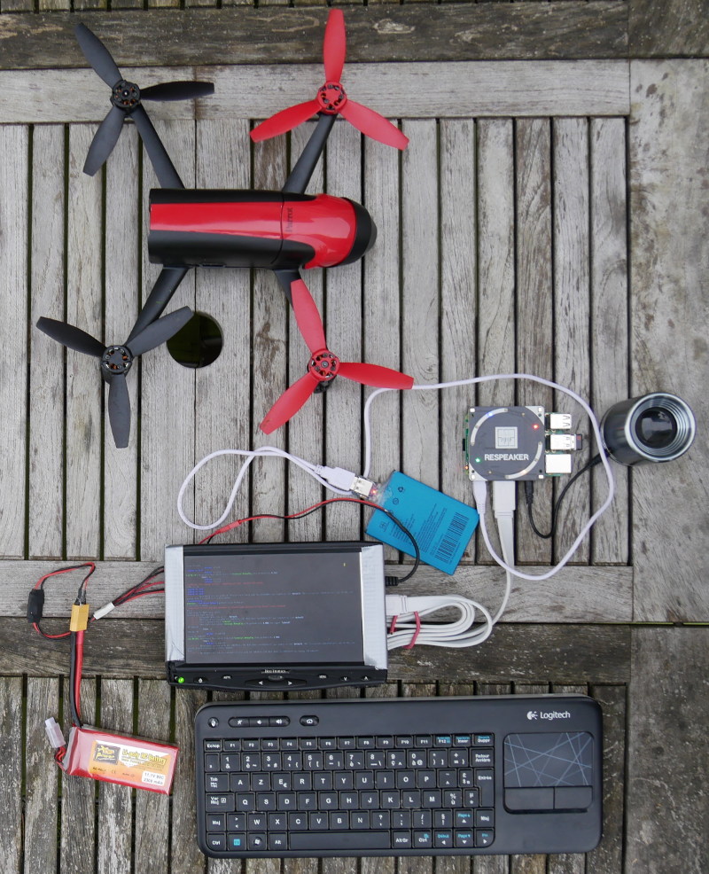
hardwarePart-800.jpg?raw=true

Hello,

I've made a proof of concept of a voice controlled UAV using a Parrot Bebop 2. Voice recognition is done in a Raspberry Pi 3 thanks to Snips.ai it is done offline, you do not need internet.

Here is a small demo :

As you can see there is about 3 second between order and action, so don't fly near obstacles !

Maybe it could help disable people to fly UAV and experiment FPV. If you find it useful let me know.

A largest use case for vocal assistant in UAV could be to talk to Mission Planner to query information about battery or altitude.

More details on my github.

Read more…

3689728968?profile=original

The quality of images taken when using UgCS photogrammetry tool is highly dependent on capabilities of the camera used. Thus the photogrammetry route has to be planned around the capabilities of the camera and not the drone.

Cameras usually have five main settings/parameters:

  • shutter speed,
  • aperture,
  • ISO,
  • matrix size
  • focal length.


Furthermore the amount of light is crucial for taking good photos. Most cameras are set to adapt to the amount of light.


Below is an illustration how shutter speed, aperture and ISO can affect the result:

3689729032?profile=original

For best results the camera matrix needs to get as much light as possible. For example:

  • if the ISO of the digital camera is set to a low value, e.g. 100, the resulting photograph will have better quality comparing to when ISO is set to, say - 1600. The higher the ISO - the grainier the resulting image will be. Whenever possible it is recommended to set ISO to a lower number;
  • when there is sufficient light, for best results the camera shutter speed can be decreased, but the speed of the drone - increased
  • If aperture will be increased, it will increase DOF (Depth of field) and the photo will be sharper.


Matrix size. The main rule is - the larger the size of the matrix, the more sensitive the camera. That’s why a DSLR camera with a full-frame matrix will give higher quality photos than a cheap camera with a small matrix.


Focal length. If the focal length is increased, then exposure time or drone speed should be decreased. Otherwise the photos will be blurry.


Knowing the camera settings, it is possible to anticipate how they affect the results of a UgCS photogrammetry mission, adding two main conditions for a drone flight: speed and altitude.


Let us analyze 3 common types of illumination during daytime:

  • sunny day with clear skies,
  • sun mixed with clouds,
  • cloudy day


Note - It is not recommended to fly in low-light conditions such as during twilight or early morning.


Sunny day with clear skies


On a bright sunny day when there is a lot of light, a test flight with DJI Phantom 4 (GSD = 2.5, True focal length = 3,6 mm, resolution – max (4000x3000 px.) was made with the following settings:

  • Flight speed = 6 m/s,
  • 'Camera by time' action set,
  • the box 'Additional waypoints' - unchecked,
  • 'Stop&Turn' turn type,
  • Overlap - default.


The route calculated by UgCS had the following parameters:

  • Height - AGL ~ 55 m;
  • Trigger interval = 3 sec;
  • Duration est. – 13 min;
  • The calculated area - about 10.39 ha.
  • Parameters of the photogrammetry tool: size of footprint - 100.00 m x 75.00 m.
  • Parameters of the photogrammetry tool: number of waypoints 44, number of passes - 11
  • Camera triggering by time: Automatically calculated parameters - 212 shots, every 3.00 s

3689728951?profile=original


The camera was set up in the field with these parameters (in Manual mode):


  1. Minimal ISO number;
  2. Minimal Shutter speed (1\160 and less);
  3. Autofocus;
  4. Phantom 4 fixed aperture = f2.8


The particular values have to be adjusted individually according to illumination. The result of the test flight was excellent: photos were clear and sharp. Only one battery had to be used for the flight with a small reserve left.

3689729072?profile=original

If the GSD would be decreased, flight altitude will also be decreased. The true focal length will remain constant; therefore, the drone’s flight speed has to be decreased or the speed of the shutter increased (exposure time decreased). The minimal trigger interval for DJI Phantom 4 is 3sec, therefore the flight speed has to be decreased. If GSD is decreased to 1.5 cm, then drone's speed has to be decreased to 2 m/s (DJI has this limitation on minimal flight speed for auto mode). Covering the same test area will require 4 batteries instead of 1 and the flight height at 20m AGL will be unsafe due to hazards such as trees.

Downside of good illumination - photos can have sharp shadows, affecting the productions of orthophoto and 3D models.


Sun mixed with clouds

The level of cloudiness has to be monitored and the settings have to be adjusted accordingly – the speed of drone and shutter speed has to be decreased, other settings can be left as previously described. The ISO value can be increased if necessary.


Second option is to use the action 'Set camera mode' with 'Shot' parameter and additional waypoints. If interval between waypoints is less then 70-90m, it is useless to increase drone's speed – the drone will not have enough distance to reach the speed set. Mostly it is recommended to use the default flight speed - 5 m/s. 


Cloudy day


The main thing to take into account when flying on a cloudy day is to fly with 'Set camera mode' action to 'Shot' parameter and additional waypoints. Shutter speed can be set to a longer time, but should not exceed 1/60. Furthermore the ISO value can be increased but shouldn’t exceed 400. 


As you can see, the capabilities of the drone exceed those of the camera. But the effectiveness of entire drone system is determined by the least efficient part. Therefore, many professional surveyors use DSLR cameras with wider lens aperture on drones with several batteries to deliver optimal and efficient result.


Get UgCS here: www.ugcs.com

Safe flights,
UgCS Team

Read more…

Secure Pprzlink released

Penguin.gif?00baf

Dear DIY Drones community,

I am very happy to announce a release of a secure version of Pprzlink. Pprzlink is a communication protocol for Paparazzi autopilot. Secure in this context means that each message send or received to or from your UAV is encrypted and authenticated. While having an encrypted communication with a UAV is by no means new (and should be the standard way of talking to drones), Secure pprzlink has two major distinctions.

First, Secure pprzlink uses a formally verified cryptographic library HACL* which is also used by, for example, Mozilla Firefox. Formally verified code is mathematically assured not to have any unintended behaviors, which is especially important for cryprography algorithms.

Second, Secure pprzlink implements a station-to-station key-exchange protocol to exchange temporary session keys before establishing encrypted connection. That way the user doesn't have to worry about key management.

Secure Pprzlink is written in C and Rust, and althogh it is mainly used by Paparazzi autopilot, it is a standalone project and can be used in other applications where secure communication is important.

More detailed explanation is on Paparazzi blog: https://blog.paparazziuav.org/2018/03/26/secure-pprzlink-released/

Give it a try and give us feedback and ask questions on paparazzi gitter channel, or via paparazzi mailing list.

Happy (and secure) flying!

Read more…

3689728985?profile=originalThere has never been a fad held in as much secrecy as the self driving car craze. It's been 15 years of startups, yet no source code or algorithm has ever been released by anyone working on a full sized self driving car, while past generations were quick to release source code for quad copters, web browsers, operating systems, & video codecs. Every Stanford student is working on some self driving car project, but with no place to start. It's like thousands of Linuxes being written from scratch, with no-one making any progress beyond what can be done in the 5 years between graduation & a better living through flipping houses.

Tried enhancing the only released footage of the Uber crash, the 1st fatality caused by a self driving car, but it was a downscaled, compressed copy of a video. The dynamic range was too poor to resolve any details in the shadow, where a human would have seen details.  The current generation has an attitude that the car did everything possible & blindly accepts the company claim that the secret autopilot was extremely sophisticated.  To someone programming autopilots for years, it didn't seem like a very capable autopilot at all.

The car was going too fast to stop in the visible distance, which for the car could have included the LIDAR range. Human drivers are told to go no faster than they can stop in the visible distance.  Someone with no ivy league degree would have at least used a better camera in a self driving car or used brights to overcome such a lousy camera. It surely detected the biker with LIDAR but lacked any ability to predict where moving objects would be in the future.  
Perhaps a former algorithm used LIDAR, but the current fad is detecting objects from lousy video using neural networks, so that's what they used.  Maybe there were so many false positives from a more sophisticated algorithm, they ended up doing nothing at all.  
The industry couldn't do any worse by being less secret, but Airbus & Boeing don't share any information about their autopilots & manage to not kill all the humans, most of the time.  
A fatality caused by a machine has a much bigger impact than a fatality caused by a human driver.  The odds might be less of getting hit by a self driving car, but it's like getting sucked into a tree shredder instead of getting shot by a human.  There's always a feeling the human can avoid what the machine can't.

Read more…

3689728758?profile=original

Well, that's happening.

I don't know what's happening inside the Ardupilot community, it's really a community project or what else?.

But as i know and you know, the community doesn't make it private any related project, Ardupilot is a Free Software and open sourced project for related projects and for well like many others.

Today, they removed and banned to me from official Ardupilot social networks and my related project called URUS (Universal Robotics Unmanned System) propossed to the community as a solution for a universal and accesible tech for drones, robotics and unmanned vehicles system that was posted and published on their community discussion about 2 years old, and it not just, because my project is a fork from Ardupilot master and master-AVR.

I'm being paranoic, but i think the purpose from some people inside the project is to opaque the good faith that have Ardupilot growing up very fast on the unmanned robotics technology world.

I will continue with development and supporting to Ardupilot project and my project the URUS System project for well.

Thank you very much to all, sincerely.

Hiroshi Takey F.

UPDATED:

The URUS work progress and info for the community was removed from Ardupilot discuss platform.

For people that want to continue following the URUS project work in progress info there is a mirror and you can see it at:

https://hackaday.io/project/18002-urus

I hope to update the info here on diydrones mirror too at:

https://diydrones.com/forum/topics/adding-urus-system-to-apm

the documentation is work in progress too there is too much for do, but i hope to update the main tutorial to build the first example, this is updated at:

https://github.com/UrusTeam/docs

and the documentation frontend is at:

https://urusteam.github.io/docs/

Thanks for all people that want the good of the URUS project purpose.

3689728820?profile=original

3689728868?profile=original

Read more…

3689728545?profile=originalHi,

After somewhat of a gap we have reached the next episode in our series of autopilot precision. In this series of videos / articles we test multiple drone autopilots in terms of precision by flying them on a simple photogrammetry route created in UgCS mission planning software.

In this part we analyse the results of Yuneec H520. Next week we will release the results of DJI M600 and after that - overall results.


See the results in the video below:

Download the KML files and take a look at them yourself in Google Earth:
https://www.ugcs.com/en/page/comparing-precision-of-autopilots-for-...

Get the newest version of UgCS here:
https://www.ugcs.com

Safe flights,
UgCS Team

Read more…

10 km high flight with a 1kg quadcopter!

I was quite surprised to see a quadcopter flying that high! It was done by Денис Корякин as shown on his youtube channel.


Specs:

Receiver: TrueRC 5.8GHz X²-AIR Antenna RHCP
FPV glasses: Furious True-D V3.5 Diversity Receiver System
Video transmission: Antenna FOXEER Thor 60mm RHCP / SMA PA1331
RC link: TBS CROSSFIRE
Motors: Cobra CM2206 / 1400
ESC: T-Motor f30a PC: Matek: f405-AIO
Propellers: Gemfan 7038
Battery: Assembling Li-ion 4s3p
Weight: 1.06kg

Interestingly, we can estimate the amount of energy spent to go that high and compare it to battery use. A quick estimate is 1.1kg * 10000m * 9.8m/s/s = 110 000 J (gravity energy), and 14V * 6Ah = 300 000 J (electrical energy). This is just above 30% of the maximum theoretical efficiency if there was no aerodynamic losses. The flight up was 17 minutes. You have to balance how fast you go up. Too fast and the aerodynamic losses are high. Too slow and you spend too much time hovering. For rockets, the optimal speed is about the free fall terminal velocity. That would seem to indicate that he could go higher by going a bit faster.

Another potential problem is motor overheating. I don't have much experience with motors that high, but the low air density can make cooling difficult.

Although those records are fun, there is a regulatory challenge associated with them. 10 km is about the height of airplanes, so you need clearance from ATC.

Have you flown higher?

Read more…

About GET
GET is the world leader in distance wireless power transmission. An electrically powered drone can recharge and fly indefinitely via efficient safe high power in-flight rapid recharging in a GET power hotspot. The company’s distance wireless charging technologies uniquely enable drone delivery and many other industrial applications.

Today electric drone flight time is just 15 to 30 minutes before batteries must be recharged or swapped. GET’s breakthrough Wireless Power Flight Platform enables battery-powered drones to fly forever between power hotspots. The Platform combines our proprietary wide-area wireless power hotspots with commercial grade drones equipped with our onboard lightweight wireless power receiving antenna and rapid charging system.

GET’s power hotspots wirelessly charge drones on the fly at a rate of over 5 kW per drone at 80% efficiency. Placing power hotspots at 3 to 5 mile intervals enables cost-effective continuous flight across the wireless power cloud network. Power hotspots are safe, operated well within world health organization guidelines, and have no interference with other communications or electronics.

GET’s Wireless Power Flight Platform enables continuous drone parcel deliveries and many other drone-based services in the energy and utilities, construction, security, mapping and surveying, oil and gas, public safety, and agriculture sectors.

GET joins over 8500 unmanned vehicle industry leaders for the AUVSI Xponential Conference held this May 1-3 in the Denver, Colorado Convention Center.

Come meet us and learn about the miracle of wireless powered flight at our exhibitor Booth 3439 – click to find more http://getcorp.com/meet-get-at-auvsi-xponential-denver-may-1-3/

Read more…

3689728554?profile=originalComNav Technology Ltd. develops and manufactures multi-constellation, multi-frequency GNSS RTK/PPK engine boards and receivers for ultimate high precision positioning applications. With more than 100000 pieces boards delivered to the market and their successful application during past 6 years, ComNav Technology Ltd. is trying to provide best GNSS solution to the worlwide customers.

For more information about the boards, pls feel free to visit www.comnavtech.com or drop an email to gnss.oem@comnavtech.com

Read more…

0?e=2120439600&v=alpha&t=1cWY6j1OLHIz66HfP4Zv5DH8SpgmxP0gsYUcS0BZdBg

Summary

In Spring 2017, Aeriosense provided its services to Allteck Line Contractors Inc., an industry leader in transmission line maintenance whose expertise ranges from design and installation to maintenance and repair of high-voltage infrastructure. Allteck was looking to achieve more efficient, more cost-effective detailed inspection of high-voltage transmission lines.

Using Aeriosense's automated drone inspection solution on an 18 km, 138kV transmission line section near Dawson Creek, Allteck was able to significantly reduce both the cost and time of inspection, as well as increase safety and reduce disruption to local landowners.

The Challenge

Conventional detailed inspections require up-close visual assessments of a transmission tower's key components. Typically, these inspections are done by either physically climbing the transmission tower or by using a bucket truck, both of which are expensive, time-consuming, and have associated safety risks that need to be mitigated.

Single pole structures can only be climbed part way while energized, giving only marginal advantage over ground-based inspection. While bucket trucks, are costly and subject to limited access in challenging terrain. The transmission line in this project goes through a rural area with farm fields and ranches, so right of way (ROW) access must be coordinated and disturbances must be minimized.

Automated Drone Inspection Tool

Aeriosense's automated drone inspection tool employs a drone equipped with visual and IR cameras, which is automatically guided to and around the structure on a pre-defined flight path. The system was used to inspect 8-12 poles from a single take off location before being taken to the next section of the transmission line.

This system allowed high-quality visual and infrared imagery to be collected and analyzed in detail without the need to climb the poles or drive a bucket truck over the farm fields.

Results

Allteck's experience with Aeriosense's approach was extremely positive. Automated drone inspection significantly reduced project costs and disruption to local landowners and dramatically increased the speed and safety of the detailed inspection of the transmission line, all while producing equivalent quality of inspection compared to conventional methods.

Inspection of the 18km stretch of 138kV line, which previously took 30 days, was completed in under 5 days, with separate inspection flights for detailed visual and thermal imaging. Significant cost savings were achieved compared to conventional inspection methods while avoiding cost overruns due to ROW access issues.

Key Results:

  • Inspection time reduced by 85%, inspection cost reduced by 80%.
  • Inspection speed of 1km/hr, 10 structures/hr.
  • Eliminated safety risks associated with climbing and bucket truck inspections,
  • Minimized disturbance to landowners,
  • Reduced time spent on project coordination,
  • Equivalent inspection quality compared to conventional inspection methods,
  • Inspection data logged, to allow future condition trending
"Compared to the bucket truck inspection we are seeing significant cost reduction in the detailed inspection using the Aeriosense tool. It also gets the job done faster, freeing up our bucket truck and personnel for other jobs. The other benefit is we don’t have to worry about rutting out and damaging the farmers’ fields"
- Kevin LaChapelle, Regional Manager, Allteck
0?e=2120439600&v=alpha&t=1cWY6j1OLHIz66HfP4Zv5DH8SpgmxP0gsYUcS0BZdBg

0?e=2120439600&v=alpha&t=ijVpw9RSFXY_10y36dSjj_pSepHbwOjJ9i-Z5bGW_2Q

Future Plans

Given the strong results achieved during this inspection, Allteck plans to make automated drone inspection part of their routine inspection for the 18km transmission line near Dawson Creek. Allteck is also exploring the possibilities of applying Aeriosense’s automated drone inspection tool to other projects in the future.

Read more…


Wind Gusts
Drones have the potential to perform many useful tasks, such as search and rescue, package delivery and aerial imaging. But in order to perform these tasks in an outdoor environment, the vehicles need to be able to control their position under the influence of wind gusts. This is especially true when flying close to obstacles, as a position error due to a wind gust might result in a collision.

Incremental control
At the MAVLab of Delft University of Technology, we have taken the concept of Incremental Nonlinear Dynamic Inversion (INDI), and applied it to the linear accelerations of MAVs. The idea is that both disturbances as well as control forces are measured by the accelerometer. This means that a desired acceleration can be achieved by incrementing the previous control input based on the difference between desired and measured acceleration.

INDI can be compared to the integrator part of a PID controller, but where an integrator is blindly adding input, INDI takes the actuator effectiveness, actuator dynamics and filtering into account. This way, it can exactly determine the size of the input increment that should be applied, and it knows when the output should be expected. This allows the controller to react very fast to even the strongest of disturbances, such as a 10 m/s wind gust in the video above. (Note that the top speed of the Bebop is 13 m/s, according to Parrot!)

Wind tunnel experiment
In the experiment shown in the video, the drone is flying in and out of the wind tunnel flow, which is blowing at 10 m/s. We show a comparison of position control with INDI and PID, both with the same inner loop control. The position of the vehicle is sent to the drone at 4 Hz using an Optitrack infrared tracking system. When flying in and out of the wind tunnel, PID control leads to large overshoot, where it takes a long time for the integrator to compensate the change in wind. For INDI control, observe that the maximum deviation is much smaller, and that the vehicle returns to the correct position in a much shorter time.

The figure below shows the top view of the experiment, where the wind tunnel is blowing in the negative XN direction, and is located at −1.425 < YN < 1.425.
3689728401?profile=original

Autopilot

The use of INDI does not require any fancy sensors, except for the accelerometer that is standard on most drones. If the position loop is bypassed, it is even possible for a pilot to command accelerations; letting go of the stick will make the drone resist any acceleration, such that it keeps its velocity.

The INDI code is included in the Paparazzi open source autopilot, but should be easy to incorporate in other autopilots as well.


More information can be found in the paper, which can be downloaded from Elsevier (free for the first 50 days) or Researchgate.

Read more…

Free Aerial Imagery Data (Personal/Commercial Use)

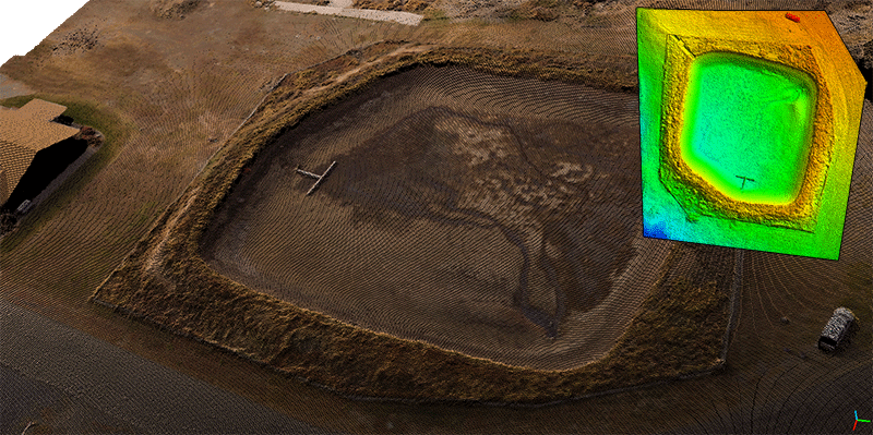
dm-4th-ave-res.png?width=600

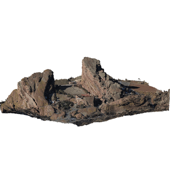
Free Aerial Imagery Data Collection JPGs, GeoTIFFs and Point Clouds!

We've updated our sample data page with a number of new drone based aerial imagery collections. These are available for personal and commercial use! We would love to hear about how you make use of these photogrammetry / drone mapping examples. There is a description of each data set located on the samples page and a combination of NADIR and Oblique collections. If you need a data set with Ground Control Points, contact us. Enjoy!

Thanks,

DroneMapperdm-data-redrocks-obl.png?width=500

Read more…

Servo Redundancy

3689728314?profile=original

I continue to develop my "full scale" gas powered, variable pitch quad-copter.

After watching the video below at 

Amazing DIY Projects

I realized (more vividly) how vulnerable a quad is to any fault in the control system.

Then I saw his video here --> Redundant flight controls where at around 23:30 in the video he informs that he will use quintuple redundancy.  That got me thinking about how I could follow the same approach using multiple independent flight controls to provide redundancy for the control system aspect of the project.  His project is different in that he has many outputs (~76 electric motors), but I only have 4 collective "swash plates" that I have to move, so the challenge was to come up with a linkage to connect multiple servos in a way that they won't fight each other, but will also be able to retain control if one of the servo's fails.

Below is an image of the non-redundant setup I'm using for collective pitch.

3689728379?profile=original

I struggled quite a bit with many different ideas, but finally arrived at this which I think is elegantly simple.

The servo arm is connected to a rod-end which is screwed into the bottom of the lower (non-rotating) portion of the swash plate. If the angle of the servo sweep is kept reasonable (60 to 90 degrees total) this arrangement does not create too much binding or bending of the servo arm.

Looking back at the first image, you can see that I've connected the servo arms together in an equilateral triangle arrangement, with the rod-end at the center of the triangle.  The motion path of the rod-end is exactly the same as it would be with a single servo.  Of course, this still needs to work if one of the servos fails. If that happens, lets assume the servo just stops moving, and stays in place (gear friction is greater than the linkage torque so servo doesn't "freewheel").

The issue here is that the rod-end only moves one-third the distance of any given single servo movement.  So with one failed servo, the rod-end will only move 2/3 the distance of the remaining two active servos.  For this reason, the servos should be adjusted so that they have 50% extra travel (only use 2/3 of their range when all 3 servos working). 

Another issue is tuning:  The system will have lower gain when one servo fails, so I will need to test the flight stability in both cases (all servo's working, and again with a failed servo) to ensure the PID loops will be able to safely control in both situations.

This design works best if the failed servo doesn't freewheel.  I'm don't think it will work if the failed servo doesn't freeze in it's failed position.

The idea here, is that each of these servo's would be controlled by a separate flight controller, so the whole control system would be tripley (word?) redundant.  Actually, this linkage concept could be extended to make it 4,5 or even 6x redundant, but only 3 servo's can be directly connected to each other by the "Y" linkage.  Beyond 3, I will need to join multiple linkages together.  

Below is a photo of my non-redundant collective linkage on my most recent test stand.  Getting ready to test the vibration of a 2 cycle engine driving a variable pitch 2 blade rotor.

3689728189?profile=original

Always interested to hear comments!

Read more…

Recently I started working on convolutional neural networks (cnn) for obstacle avoidance. With the help of "DroNet" from ETH Zurich and the "Deep Learning for Computer Vision" book from Adrian Rosebrock, I managed to build my first cnn algorithm for obstacle avoidance. The cnn module is written in python, using a keras module with tensorflow backend. I included my cnn algorithm in a dronekit script. By sending mavlink distance messages to the flight controller in loiter or altitude hold flight mode, my drone is able to avoid obstacles. A brief description and demonstration of the developed cnn is given in the YouTube video. First results are promising.

Read more…

IR Laser Night Vision Zoom Camera For Drone

Sky Eye-12NLT is one 1080P 12X zoom camera designed for multirotors to conduct night vision mission like inspection,surveillance,search and rescue,due to its powerful night vision capability.It consists of one 1080P 12X stellar zoom camera and an IR laser illuminator served as an auxiliary IR light for the zoom camera.The 12X stellar zoom camera features super low illumination:0.0005lux/F1.5(white/black),is able to spot the object as far as 500 meters in the night with the help of IR laser illuminator.

Sky Eye-12NLT offers an wiring hub for wiring and video out(HDMI output),which makes wiring pretty easy and clean.Also the gimbal provides 2 smart speed modes:FAST speed and LOW speed.Fast speed mode is used for small zooming range,which makes the gimbal control sensitive and quick.LOW speed mode is used for large zoom range,will enable you to target the object more accurately.

Sky Eye-12NLT comes with an outstanding advantage that the gimbal can not only be controlled via PWM signal,but also serial command.Also gimbal data(like Yaw/Pitch/Roll angle,zoom status etc) can be obtained by sending serial command to the gimbal via its serial port,which is really useful for precise gimbal control and system integration.

2 useful features are available on Sky Eye-12NLT.The first one is tracking,which will enable the pilot to track object freely during daytime or night time.The second one is geotagging,that means the gimbal will geotag the gimbal position on video streaming or photo that you currently choose on screen,and GPS coordinate will be displayed on the screen too.

So to sum up,in the daytime,Sky Eye-12NLT is a normal zoom camera for drone.And in the nighttime,the gimbal can be used to monitor targets that normal daylight camera can not.

Features:
1) Weight:1265grams
2) 1/1.9 inch 2MP CMOS sensor
3) 12X optical zoom,12X digital zoom,HDMI 1080P/30 video out for video downlink
4) 1080P/30 H.264 video recorded for on-board TF card
5) Super low illumination:0.005lux@F1.5(colorful),0.0005lux@F1. 5(white/black)
6) IR laser illuminator cover range: over 500 meters
7) Auto object track and geotagging
8) PWM control and serial command control
9) Convenient wiring hub for RC receiver and video output(AV and HDMI)
10) 3-aixs high stabilized gimbal system
11) Adjustable control speed: SLOW speed for large zoom range,accurate.FAST speed
for small zoom range,sensitive and quick.
12) One key back to center

Product Link:http://www.yangdaonline.com/sky-eye-12nlt-12x-1080p-ir-laser-night-vision-zoom-camera/

Product Photos

3689728151?profile=original

3689728220?profile=original

3689728272?profile=original3689728174?profile=original3689728242?profile=original3689728296?profile=original

Read more…