If you're interested, please follow our one-minute open-source contributors tutorial and let us know once you have an improved proposal for the look-and-feel. Please use a new folder for image files and back up the old CSS file, so that users can eventually choose between different "skins". In general we made good experiences with the current coloring, but we're open for completely new ideas.
All Posts (11086)
Sort by
so I bought an easy star and decided to do things right and use it as a surrogate body with a little forgiveness. So, without further adieu, I present to you all! The CHRIS FLYER! Which should hopefully be flown tomorrow (without GPS) (http://www.diydrones.com/forum/topics/baud-rate-change?xg_source=activity)
Homemade Spacecraft from Luke Geissbuhler on Vimeo.
that combines vertical take off with conventional fixed wing flight. This video is apparently of the miniPanther weighing 12kg and with 2hour endurance.
Peter
DIY Drones is featured in this week's installment of my favorite tech show, the excellent Robots Podcast, which interviewed me a few weeks ago. From the writeup:
"The [DIY Drones] community relies on a development team of more than 100 active developers contributing to about a dozen projects, both hardware and software. One of their products, the ArduPilot autopilot, can be strapped to your flyers for autonomous control. In a rather new twist in the industry, DIY Drones focusses on making open source hardware that can be used by all in the same spirit as open source software.
Anderson covers all the questions you ever had about making flying robots, including safety and legal aspects. He also discusses risks in putting this technology in the wrong hands and some anecdotes of crazy projects coming out of the community."
Check it out here. And subscribe to hear all the podcasts, which cover loads of ground of interest to this community, from other UAV issues to basis research on AI and locomotion. It really is a must-listen production from a crack team of researchers at a top Swiss robotics lab. Highly recommended.
First, I will conclude what I am plannign to do: being a professional software developer for a decade or so, i am building a drone by transferring my knowledge of software projects to this. Hence, the first part was finding use cases and such, and finding preconditions that i want to meet.
Some preconditions are:
- tier structure - arduino == platform driver, android == command gateway, webgui == user interface
- as few soldering and custom parts as possible
- exclusively open source, and free software as far as possible (some might have forgotten - there is a difference)
- web-based (i really dont want to mess around with r/c electronics and reach and such)
- swarm-alike - each drone should be aware of all others, be able to communicate with each other and to help and replace each other (for example seamless drone replacement in POI mode)
Matrix Pilot Camera Targeting: Tree Test - Software Stabilized
Strategy: Have MatrixPilot / UAV DevBoard (UDB) point camera roughly in the right direction.
Take out the jitter movement using software stabilization.
The above flight was flown on a day with 10mph of wind, with a lot of turbulence (I included the landing in the video to show the turbulence).
1. The UDB is calculating its orientation 40 times / second using a 16 bit Direction Cosine Matrix
2. I use se Bill Premerlani's "High Bandwidth Dead Reckoning", which means MatrixPilot knows it's
absolute position 40 times / second, by integrating the accelerometers. The accelerometer positions are
corrected by allowing for the GPS delay and some of the GPS dynamics (GPS info arrives at least 1
seconds after the real event).
3. The camera code computes the target location from the above 40 times / second.
The main issue at the moment is that I'm using a camera with progressive scan. This causes each frame of the image to be distorted when the camera rotates (accelerates) in a new direction.
Pitch Servo resolution is 0.2 degrees which translates into moving the picture 7 pixels. Ideally it would be at least 1/10th of that, e.g. 0.02 degrees.
Photos of the build of this project are here.
Main Wiki for MatrixPilot is here.
For reference the flight path, in autonomous mode, is shown below.
This guy knows how to rock that quad!
Motors: FC 28-22 1200kv
ESC : HK SS 25-30A
Props: 8 x 4.5
The mods for the 9ch TX display are coming along nice.
The current display is shown.
Mods for it are coming for different screen modes.
Use XBee to receive data to be displayed on TX.
TX does need programming as in this place.
http://www.rcgroups.com/forums/showthread.php?t=1266162&page=157#post16340409
Late happenings at ArduCopter "Factories"...
Another milestone on releases, few weeks ago we had our first official Alpha software release and now saga continues..
It's been long and fast ride in past 6 months. It all started as a dream to create nice expansion for original ArduPilot electronics. Then Jordi and others created new even better and more compact electronics for IMU use, after that people started to create more and more their of flying devices. So finally we decided to take it to next level. Level of ArduCopter and it's full line of electronics, frames and other R/C equipment.
We on development group owe a bit thanks to the whole DIY Drones community and people who are playing key roles on it. Now we already have nice and rather well working ArduCopter software written for the latest hardware and well working fixedwing software so things are looking good on our users perspective. Sure there are still many things to develop, and new development happens every single day, maybe some of our users won't always see it but there are a lot of things done behind the scenes.
In totally on ArduCopter project it self we have around 20 people working with it, some as occasional commiters, some of us are more or less working as full time and some even all day around 7 days per week... Why, well we just like it a lot and we want to provide these good experiences to our users.
I should not need to tell that what we are trying to do here but let's say it anyways. Thing what we try to accomplish with ArduCopter and ArduPilots projects in generally is to create low cost and easy to use UAV platforms that can be extended easily to higher levels. We try to keep designs as simple as possible so people even with low mechanical skills would be comfortable to build them and enjoy of flying.
Naturally our platforms is not for everyone but at least we try to make it suitable for as many as possible. And you can be part of that process. So if you have any ideas just let us know. We are constantly looking new ideas and ways to do things.
ArduCopter KITs
Long waited time has come. We have been using hundreds of people to find all suitable parts and part providers for us, thousands of emails has been sent back and forth and now finally ArduCopter v1.0 release is at hand.
Also long waited prices for KIT's are here too. Our original goal was to create a multirotor platform with less than $1,000.00 USD, and yes Sir, we did it. Actually we did it way under of our first price goals. So here they finally are:
ArduCopter Quad v1.0 Full KIT price will be $499 USD
- ArduPilot Mega
- ArduPilot Mega IMU / OilPan
- MediaTek GPS
- Needed connectors for GPS and APM
- Motors (850kv), ESCs (20Amp), 10x45 Propellers
- Full Frame kit
You only need to add Radio/Receiver and battery to make it complete.
ArduCopter Quad v1.0 Frame KIT, $290 USD
- Full Frame kit
- Motors (850Kv), ESCs (20Amp), 10x45 Propellers
ArduCopter Quad v1.0 Frame itself $160 USD
- Just all frame parts
All frame KIT's have Fixed delivery price of $55 USD and it works most of countries. But due some countries can have high delivery costs, we will cover extras costs as long as they stay under 25%, if it goes more than that we might need to charge small extra for delivery. We are constantly looking better and more economic methods for deliveries.
Hexa and other frames will be available later after basic production is running properly on Quad frames. There also is going to be full range of extra accessories and spareparts for all frames.
Frame itself contains parts like in earlier Beta frame had plus some extras and upgraded parts based on our beta tester comments and proposals. Main changes are in Arches, Power PCB, MotorMount, New choices for arms, landing gear fins, spareparts and also some extra connectors are included on this new frame kit.
Originally we planned to have pre-orders and Asian/European orders under PhiFUN but due legal issues and taxation, we moved it to more official company to ensure that everything is done legally. So we are using Fah Pah Electronics new site that I have been building last week for all our deliveries. All PhiFUN operations has been moved under Fah Pah. (My working table is still on same place and full of tiny AC parts as always hahah).
After normal deliveries has started, ArduCopter KIT's and parts can be found from following shops:
http://store.diydrones.com (for US only)
http://store.jdrones.com (rest of the world)
There will be few local distributors, their names/locations will be announced later (edited to here)
Estimate to start deliveries is now on 1st week of November. Depending on how our Motor and ESC shipment is arriving from factory. We are keeping parts arrival records on our Wiki so check it out.
Now let's fill the world with ArduHappines :)
Cheers,
Jani / The headless ArduCopter man on Youtube ;)
Our IT guys found this in a closet. It's an old quadcopter that uses thermopiles rather than gyros for stabilzation. It's RC only, but it's got a big old webcam on a stalk. Like a Parrot AR.Drone from the dark ages!
The only identifying writing on the board says "Spectrolutions, 2004" and when you Google that it comes up with this site, which shows a very similar board with "Draganfly" markings. Maybe this is a prototype of an earlier version of the current DraganFly?
[Update: it looks like it is indeed a prototype of the DraganFly V, which came out that year. Here's a good pictoral history of that development]
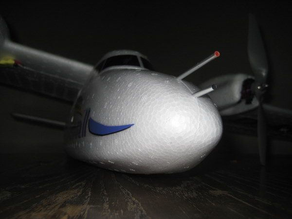
Here’s a build log for my Ardupilot Mega Twinstar II. Hopefully the included photos will be useful to anyone trying to decide which airframe to buy and wants to get an idea of the space in this model.
Overall, I am very happy with the Twinstar, my build didn’t require many modifications to the standard kit and the instructions in the box are pretty good. I’ve upgraded it to a brushless setup with a 3 cell lipo for power as it is cheap and sooo much better. I’ve included a full parts list at the bottom.
The great thing about the twinstar is it comes with an APM sized hole on the CG! (which by the way is a good thing for the IMU).
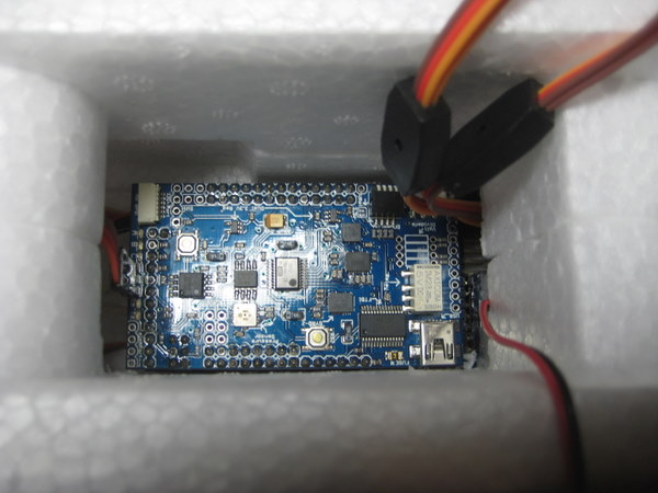
Okay, so a little bit of shaving is required on the left hand fuselage half. And as I later discovered, its best if you put a straight pin header on the airspeed sensor connector, not the right angled one shown here. Otherwise you can’t pull it out between the wing bolts so easily.

This next picture shows my chosen component layout in the fuselage. I’ve gone for servos in the standard location for simplicity. The receiver I am going to put in the rear as the servo connectors on the APM must point backwards, and I have a switching mode power regulator just below the rear wing bolt.
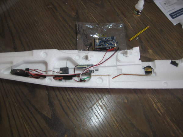
If I want to change the receiver in the future, I’ll have to cut it out, but I imagine I can patch it up again no problem. If I need to rebind the receiver that’s also covered, as I put a y-lead on the battery connector, one end going out the side of the fuselage, the other end to the voltage regulator.
I cut out a hole for the servo wires from the receiver and then hot glued them in place with the APM in the fuselage, being careful not to get any glue on the APM itself. This means that the APM can be simply pushed into the servo connectors and all 8 inputs are wired up in one go. I made my servo wires to fit, and in retrospect, I would have bought some 8 long female headers instead of servo connectors for the APM end. I also cut a slot out for the USB connector.
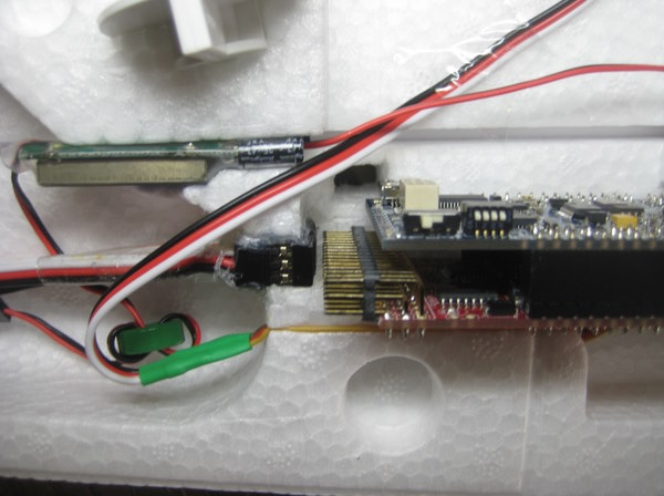
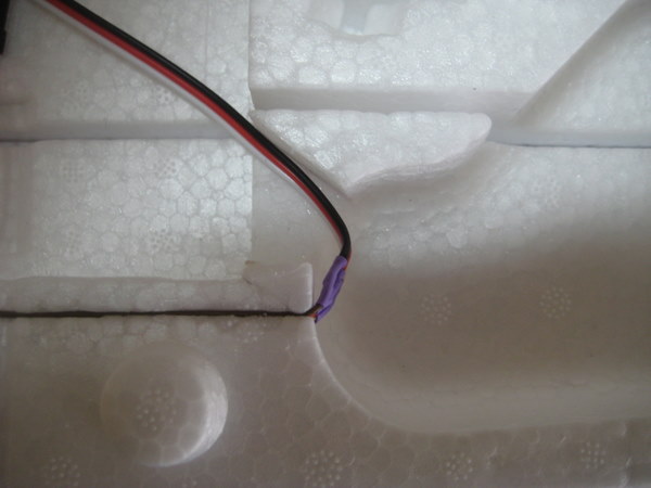
On the other fuselage half, a hole for the output servos must be cut. Here the rudder servo wire can be seen passing by. The wire is embedded in the foam, so as not to interfere with the underside of the board, and then appears through the newly cut gap. When installing the APM, that wire is going to get pushed back into the compartment behind.
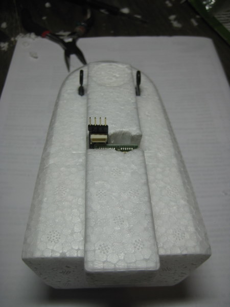
The pitot tubes go in the nose, so the airspeed indicator should probably go somewhere near by. Here’s my choice. I have put velcro hook and loop tape on the sensor so if it needs re-plumbing when I end up bending those tubes, its easier to remove and put back. For the connector, I used a 90 degree header, but soldered it at an angle, so that the output is pretty much in line with the fus.

I then cut a v shaped channel in the fuselage half for the tubes, tacked them in place with CA, and then offered the other fuselage half up, squeezed them slightly, leaving an imprint of the pitot tube location. Then I cut a corresponding v.

Here is a picture showing the string that I’ve attached to the board to help pull it out of the hot glued servo connectors. As it is a snug fit after all :) When it is in place, take a look at the two cutouts on the fuselage in-sides where the tailplane snakes are installed. These provide excellent ‘rails’ for sliding back a piece of card to above the APM, providing protection from the wires coming from the wing.

The GPS unit goes nicely in the canopy, which essentially provides it with a massive amount of protective foam. I didn’t feel the need to have it protruding out the top either, I’m sure the foam will not interfere with the signal. Oh, and it’s best to remove the 4 pin header (only required for FTDI connection if yours wasn’t pre-programmed) or you’ll end up spiking a wire or battery!
The motor supplied is about the same diameter as my selected brushless motor, only longer and 20g heavier. So the mount requires shortening. Being an outrunner, the outside of the brushless motor rotates, and so clearance between it and the flanges on the mount is more critical- so these will require filing down a little bit too.
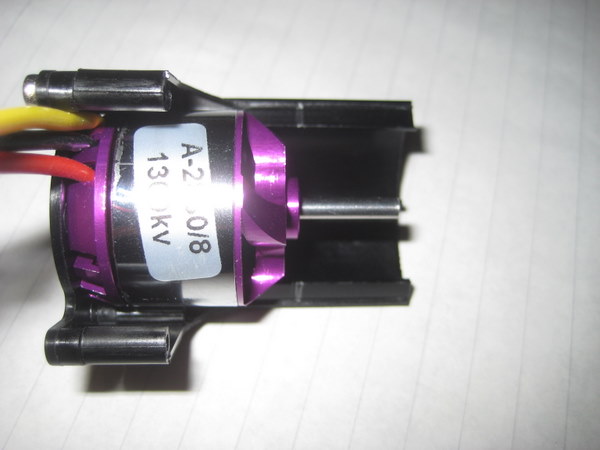
I’ve installed the motor mounts facing the opposite way to the way shown in the manual such that the load from the motor isn’t pulling on those four feeble looking self tappers that hold on the mounting plate.
I wanted the ESC to be in the airflow to give it a good amount of cooling, but didn’t want it to ruin the aerodynamics of the wing. So I opted to cut into the motor nacelle slightly and CA the ESC in place such that the smooth side is flush with the surface of the wing. The only real protrusion into the airflow is the capacitor.
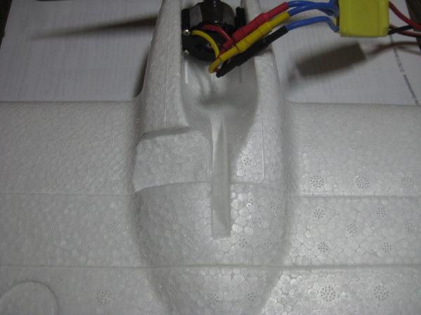
The wires (all of which I had to extend) can then be run into the foam as per the manual, before gluing on the spar cover. As there are quite a few wires running down here, I tacked them in place with some CA to help alignment and minimise trimming of the cover.
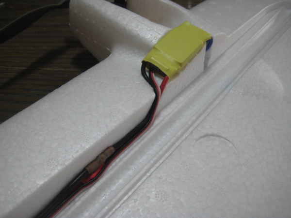
I also broke the connection on the middle red wire coming from the ESC to disable the included BEC. This means that I don’t have to use the less efficient linear BEC and as an added bonus, can power on without the wings attached if testing.
I used a smaller servo than the recommended, but with enough glue I believe it won’t move around within that over-sized cut out. Also, the decals can be used later to smooth the wing where there is now a big gap.
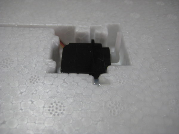
Finally a power wire needs to be made with 3.5mm gold plugs for the battery end, positive male, negative female. The other end is connected in parallel to two (female) deans connectors for the ESCs as well as a single JST (male) connector for the radio power supply (the switching mode voltage regulator or “UBEC”). The lipo is held in place with velcro, for which I bought the branded stuff, the kit supplied didn’t appear to be all that strong. I originally went for counter rotating props in this, but my APC props were so out of balance that I had to put some cheapo GWS ones on until my blade balancer arrives.
I took a lot of pictures during the build, so more are available upon request. Here’s the part list, which after postage, without the transmitter and receiver comes to around £500 (in the UK). Also the take off weight is 1.3 kg
I took a lot of pictures during the build, so more are available upon request. Here’s the part list, which after postage, without the transmitter and receiver comes to around £500 (in the UK). Also the take off weight is 1.3 kg
| Part | Model | Quantity |
| APM | 1 | |
| Oilpan | 1 | |
| Airframe | Multiplex Twinstar II | 1 |
| Motors | 1300kv 28mm by 30mm 50gr outrunner | 2 |
| ESC | 30A unbranded | 2 |
| UBEC | 3A Switching mode unbranded | 1 |
| Servos | Emax ES08D 8gr digital servos | 4 |
| Lipo | 3000mAh 3 cell Loong Max Tipple | 1 |
| Propellers | 9x6 | 2 |
| Servo wire | 6 metres is plenty! | 1 |
| Servo connectors | 10 pack male | 1 |
| Power connectors | 2x Dean pairs, 3.5mm gold, JST male | 1 |
| GPS receiver | uBlox | 1 |
| GPS adaptor | diydrones adaptor | 1 |
| GPS cable | 30cm is more than long enough | 1 |
| Pitot tubes | Bought spares! | 2 |
| Airspeed sensor | MPXV7002DP | 1 |
| Xplane | Version 9 | 1 |
| Transmitter + Receiver | Spektrum DX7 + AR7000 - this may change when I add telemetry | 1 |
I have successfully flown this a handful of times now. It flies superbly- very stable with plenty of climb out performance. I haven't worked out the flight time yet as I've been tinkering a lot, but I reckon it could comfortably cruise for 15-20 minutes.
The stock settings for the APM work very well indeed. As do the default FBW-B speeds- the minimum of 6m/s looks very slow and I was worried about it stalling at first, but it had no problem in keeping its height and attitude rock solid :)
Anyone out there have any experience with connecting a cellular modem to the ArduPilot Mega? My intent is to create greater/more reliable down/uplink range. If a radio modem has the capability, it doesn't seem too much of a stretch to think that a cell modem could.
JFK
I found the plane and I think it looks very much like the foam Skywalker version.
The model is made in strong GF and has a wingspan on 1.6 M.
Wings are made in balsa and the total weight is around 1 kg.
Here you have some pictures.
The foam version of the UAV and FPV planes
No more intell about new frames or platforms. ;-)
This caught me out big time. And I thought it might be of help to someone else to post my experience even if it was foolish.
The scenario: I have two AP one with V1 shield, Thermopile sensors. Second one with V2 shield with IMU +V2 I only have one GPS EM406 that I swop around (waiting to get UBlox) for second AP.
The problem: I could not get the throttle to work on the First AP every ting else work fine, after rereading the manual rescan the discussions and blogs for similar problems I found some and try all the options only to end with the same problem –no throttle-. Now I started to swab shields around. I want to add that if I remove the shield the throttle works fine.
The result was and a good lesson not to take short cuts when building. When I soldered the pins of AP1 I have also soldered in Pin 13 so instead of de-soldering pin 13 I have just cut the pin flush to the plastic base. Everything was fine till I used Velcro to strap the AP to the base in the airframe it put enough force on the shield to make pin 13!! . I will not repeat the names I called myself.
The lesson Read the manual on the lines and between the lines and do not take any short cuts it will bite you!!
Toward the end of the video you can see the crash. The plane is trying to follow a runway beam but winds up oscillating back and forth and eventually tip stalls. The only thing that saved me from ending up on the roof of the barn was accidentally flipping on the autopilot for 1/4 of a second as I was in a panic flipping every switch.
My beamfollow is what I suspect caused the crash. It works like this:
1) The "beam" is created and basically defines a path to follow. It is assigned a bearing.
2) I get the distance from the aircraft to the beam. 30m out the bearing command is perpendicular to the beam. As the aircraft gets nearer and nearer, the bearing command converges to the actual beam bearing
3) The aircraft follows the beam bearing by feeding the bearing error into the bank command (The aircraft simply banks toward the bearing)
If the aircraft is going decently fast, there aren't any issues. But something oscillates when I go slow, and especially when I just hover in the wind making no progress as in this video.
So the two bugs are:
1) Beamfollow oscillations induced by low airspeed
2) Altitude was lost making all the turns, making recovery impossible.
3) Probably flying 30 feet above the treetops in gusty winds made for all sorts of funky air currents.
I've learned 2 things from all this:
1) Don't ignore strange behavior. It WILL happen near the ground one day.
2) FAILSAFE MODES! Plane should recognize dangerously low altitudes or oscillations and enter a wings level climb and alert the user.
The damage? Stripped aileron servo gears, Cracked left aileron, busted pitot tube, chipped prop, and a few cracks on the fuse. She'll fly again in a few weeks!
Seeeduino Film Motion Frame is a motion sensing extension board designed for Seeeduino Film. It’s flexible, super slim, and suitable to build wearable applications.
It consists of a barometer, 32Mbit flash and a 3axis accelerometerSensor to provide sensing and logging of eight, temperature, air pressure, motion. FILM and other extension FRAMEs could be simply connected via the 20p universal bus like a chain, native 2.54mm pitch pins also enable quick prototyping.
Features
- Seeeduino Film compatible
- Flexible
- I2C 3-Axis Accelerometer
- I2C Barometer
- SPI 32M-BIT flash
- Ultra small/slim form factor
- 0.1” pitch pad breakout
- 20pin daisy-chain flex bus
- Transform by cutting and chaining
- Reinforced to increase endurance
Application Ideas
- Sports and Gyms
- Aviation
- Hiking/Climbing
- Data logging
- Environment Sensing
- Security
Documents
As part of my slow but sure attempt at entering the competition I have created a simple but effective solution to this part of the rules using a Ray casting algorithm and running this on a Netduino in C# (easy to convert to Arduino).
Here is the code to test if the current location falls within a polygon:
public static bool LocationInsideBoundry(Position point, Position[] boundry)
{
bool insideBoundry = false;
try
{
int j = boundry.Length - 1;
for (int i = 0; i < boundry.Length; i++)
{
if (boundry[i].Longitude < point.Longitude && boundry[j].Longitude >= point.Longitude ||
boundry[j].Longitude < point.Longitude && boundry[i].Longitude >= point.Longitude)
{
if (boundry[i].Latitude +
(point.Longitude - boundry[i].Longitude) / (boundry[j].Longitude - boundry[i].Longitude) * (boundry[j].Latitude - boundry[i].Latitude) < point.Latitude)
{
insideBoundry = !insideBoundry;
}
}
j = i;
}
}
catch (Exception)
{
return false;
}
return insideBoundry;
}
Pretty simple stuff and works a treat.
Here is a simple app in .net that shows if the current location is inside the boundary – drag the map around with the right mouse button add some points and if the location is inside the boundary then the group box background will be green – outside then red.
Hopefully it will be of some use.
Cheers
Justin
