All Posts (14048)

Sort by

Bixler with ArduPilot flying Waypoints

Just an update on my previous Blog Post.  I have tested Loiter, RTL and Waypoint navigation on my Bixler Plane. 

So far I am happy with the results.  There was a bit of wind on this specific day.  I also tested waypoints at 100m Altitude which I was looking forward to seeing the end result myself.........but my camera battery went flat.......... 


Chris you are welcome to link some of these videos to the Arduplane site.....


Pictures of my plane with GoPro Camera.3689435294?profile=original

3689435227?profile=original

Video's of Waypoint flights

https://www.youtube.com/watch?v=njTb_Tbd6CI

https://www.youtube.com/watch?v=-qtRcn_wZQo

https://www.youtube.com/watch?v=PbHMyzBpwR4


Read more…

MookaFrame: New 3D frame

I am trying to convince me that AC2 can fly better...

So, in my spare time, I designed this new frame. I think to send in production (ponoko?) as soon as possible.

The concept is that everything, especially motors, must be protected.

I definitely must add the landing gear, propeller protection and camera mount, shouldn't I?

Any suggestion appreciated.

3689435255?profile=original

3689435193?profile=original

3689435220?profile=original

3689435268?profile=original

Read more…
Developer

Sailboat Autopilot Design for ArduPilotMega

We just finished up modeling sailboat dynamics and implemented a controller. The dynamics were interesting due to the swinging airfoil. We modeled the winch system using a basic spring model that can only pull the sail in. It works well and can simulate irons, tacking, and jibing. All of the drag coefficients etc. are very rough at this point but the overall dynamics seem realistic.


The sailboat we are using is a 1/3 scale laser sailboat and we hope to have it sailing with the autopilot soon. The autopilot will be implemented for ArduPilotMega using the ArduPilotOne library.

 3689435320?profile=original

For the controller we are using a feedback system on the rudder to hold the commanded course. We are using a lookup table for the desired sail position given the apparent wind direction.


We have rigged up a wind indicator using a coil wound variable resistor that can easily plug into one of the existing 5 v adc slots on the apm. We removed the stopper so it can freely rotate.

3689435337?profile=original

Read more…

As part of Centeye's participation in the Harvard University Robobee project, we are trying to see just how small we can make a vision system that can control a small flying vehicle. For the Robobee project our weight budget will be on the order of 25 milligrams. The vision system for our previous helicopter hovering system weighed about 3 to 5 grams (two orders of magnitude more!) so we have a ways to go!

We recently showed that we can control the yaw and height (heave) of a helicopter using just a single sensor. This is an improvement over the eight-sensor version used previously. The above video gives an overview of the helicopter (a hacked eFlite Blade mCX2) and the vision system, along with two sample flights in my living room. Basically a human pilot (Travis Young in this video) is able to fly the helicopter around with standard control sticks (left stick = yaw and heave, right stick = swash plate servos) and, upon letting go of the sticks, the helicopter with the vision system holds yaw and heave. Note that there was no sensing in this helicopter other than vision- there was no IMU or gyro, and all sensing/image processing was performed on board the helicopter. (The laptop is for setup and diagnostics only.)

The picture below shows the vision sensor itself- the image sensor and the optics weigh about 0.2g total. Image processing was performed on another board with an Atmel AVR32 processor- that was overkill and an 8-bit device could have been used.

3689435112?profile=original

A bit more about optics: In 2009 we developed a technique for "printing" optics on a thin plastic sheet, using the same photoplot process used to make masks for, say, making printed circuit boards. We can print up thousands of optics on a standard letter size sheet of plastic for about $50. The simplest version is a simple pinhole, which can be cut out of the plastic and glued directly onto an image sensor chip- pretty much any clear adhesive should work.The picture below shows a close-up of a piece of printed optics next to an image sensor (the one below is a different sensor, the 125 milligram TinyTam we demonstrated last year).

3689435074?profile=originalThe principle of the optics is quite understandable- a cross section is below. The plastic sheet has a higher index of refraction than air, thus a near hemisphere field of view of light may be focused onto a confined region of the image sensor chip. You won't grab megapixel images in this manner, but it works well for the hundreds of pixels needed for hovering systems like this.

3689435090?profile=original

We are actually working on a new ArduEye system, using our newer Stonyman vision chips, to allow others to hack together sensors using this type of optics. A number of variations are possible, including using slits to sense 1D motion or pinhole arrays to make a compound eye sensor. If you want more details on this optics technique, you can visit this post, or you can pull up US patent application 12/710,073 on Google Patents. (Note: We are planning to give a blanket license of the patent for use in open hardware systems.)

(Sponsor Credit: "This work was partially supported by the National Science Foundation (award # CCF-0926148). Any opinions, findings, and conclusions or recommendations expressed in this material are those of the author(s) and do not necessarily reflect the views of the National Science Foundation.")

Read more…
3D Robotics

Pop-up fabrication of a robotic bee


From the video description: 

The Harvard Monolithic Bee is a millimeter-scale flapping wing robotic insect produced using Printed Circuit MEMS (PC-MEMS) techniques. This video describes the manufacturing process, including pop-up book inspired assembly. This work was funded by the NSF, the Wyss Institute, and the ASEE. Music: D-Song by Bonobo

See "Pop-up Book MEMS":
https://micro.seas.harvard.edu/publications.html

Read more…

Releasing the shackles - how far do you want to go?

FATBOX_GPRSV2.JPGSince I got into building my own drones I have been fascinated with the prospect of extremely long range drones that are not restricted by the limits of point to point wireless technology.

The public cell network seems like the perfect solution for long range drones as it covers most countries and now supports extremely high bandwith.
I've done some experimenting with the dronecell and various other options but they have all missed the mark somewhat in some way.

I stumbled across this solution the other day and it seems like the perfect solution for larger very long range drones.
The FATBOX GPRS2 is a wireless DTU with a few extra bits of trickery that lend it as the perfect long range solution for our needs.

  • Serial port - The serial port can be interfaced to the APM mavlink port (the same one used by the XBee) with the simple addition of a TTL level converter.
  • Dynamic DNS - it has a built in Dynamic DNS client, this means when you turn it on, it automatically connects to the internet via the builtin GPRS modem and registers its IP address with a DDNS provider. This means you can simply type in the DNS name into the mission planner to connect to the APM without needing to know the IP address.
  • Transparent - unlike most GPRS modems, the Fatbox can be setup to be a transparent serial router. When you turn it on, it exposes the serial port over UDP on its IP interface. As the APM mission planner supports UDP, it should be plug and play.
  • Dual SIM - if coverage is an issue, you can insert two SIMs from different providers, if it loses its connection, it will automatically connect with the other SIM and register its new address with DDNS. You will get a brief dropout on your APM planner but can then just reconnect.
  • Ethernet interface - this is the kicker for me, it has a built in ethernet interface that can be used at the same time as the serial port. This opens the door for video or any other ethernet based device you might want to add to your drone. You could also add a wifi link for redundancy and access the serial port via wifi and fall back to GPRS if you go out of range.

The only downside is that out of the box it weights 420 grams.

It comes in a steel case and the board itself only weigh 120 grams so I am going to look at other case options or perhaps just fly it naked.

Mine should be here soon so watch this space for the results of my testing.


* note: In some countries, by default your SIM card is on a firewalled APN which means you can't contact the IP address over the internet. This is usually just a case of ringing your provider and asking for the name of a non firewalled APN.


Read more…

3689435049?profile=original

Black Friday, 2011. The boss comes in with a plastic bag. I'm the only one in the office--everyone else is out shopping.


"I've had an epiphany," he says.


That's never good.


He proceeds to dump out the bag. A small pile of tinkertoys, a couple of moustraps, and a thin cross-bar to a Christmas tree that probably hasn't seen St. Nick in 40 years.


"We need to be making these copters out of stuff ANYONE can get their hands on. Cheap and dirty and quick."


That's how the SMAP center students from UAHuntsville and Calhoun Community College in Huntsville, AL started the Tinkerbot build. We've been building multicopters for about a year, testing and building and flying and lots and lots of crashing, all in the name of research. We scrounged together enough parts...


We sawed the mousetraps in half and mounted some spare Robbe Roxxys to them, then glued--yes, glued--the mousetrap to a tinkertoy hub which fit right over the end of the tree stand (more glue here). Using only more tinkertoys and more hot glue, we created the chassis around the center of the stand and glued some spare ArduPilot guts to the middle. 


Then, on the only clear day in Alabama in the fall, we took the thing out to see if it would fly.... I hope you enjoy.

Read more…

FPV Media Coverage

TBS has been invited to SternTV, one of the most renouned and respected TV shows on german TV. We did a small edit of our day there, check it out:

Read more…
Developer

Please welcome ArduPilotMega 2.0!

3689434949?profile=original APM 2.0 is the culmination of almost a year of hard work. We wanted to make it perfect and we finally have it, we are pushing the limits of AVR and Arduino. I’m sure you will love it, and it’s designed to cover all the DIY community expectations (including those that are not so DIY and are only interested for something that doesn’t require soldering skills). 


Check the product listing for availability status!


Main Features

  • Three processors--a triple-core autopilot!
  • All new state-of-the-art sensors; the first autopilot to use the Invensense 6DoF MPU-6000
  • Smaller, lighter, cheaper than APM 1.0--just $199 ready to fly, with GPS, magnetometer and dataflash included.
  • Like APM 1.0, this is the world's only Universal Autopilot. The same hardware can autonomously control planes, multicopters, regular helicopters, rovers, even boats, with just a one-click firmware change--no programming required! Best-of-breed mission planning and two-way telemetry, and soon with advanced scripting with Python for robot acrobatics and more.
  • Twice as much dataflash memory, with SD card slot
  • No soldering required
  • When using the internal sensor fusion processor of the MPU-6000, more than half of the Atmega2560 processing capacity is free for new advanced features.
  • Native USB, with all new PPM encoder software


3689434962?profile=original


New sensors

The big advance in APM 2.0 is the introduction of the Invensense MPU-6000 sensors, which have an internal Digital Motion Processor (DMP) that does advanced sensor fusion. We’ve tested it for months, including lots of flying, and it significantly outperforms the DCM used in APM 1.0. It’s your choice whether you want to  use the MPU-6000 internal sensor fusion or do it yourself in the main processor, but if you choose the DMP it frees up nearly 40% of the processing power in the Atmega 2560. This is a digital chip, so we were able to eliminate the ADC chip used in APM 1.0, lowering chip count along with cost and size.

We’ve also upgraded the barometric pressure sensor to the MEAS MS5011, which has a resolution of 10cm! This is at least twice as accurate as the pressure sensor on APM 1.0 and should give ArduCopter best-of-class altitude hold capability. Here are some of our side by side tests conducted by Jose Julio (Spain):


3689435013?profile=original
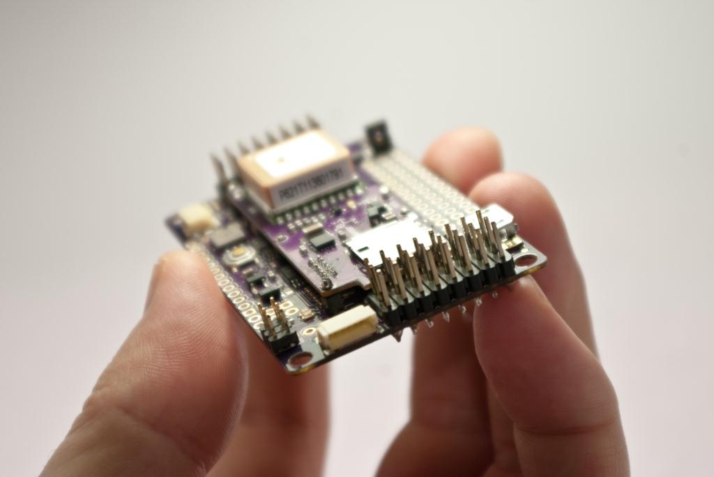
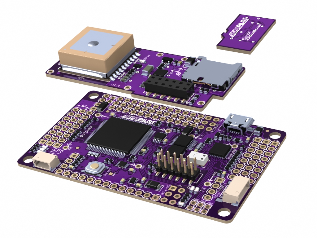
We joke about the color of APM 2.0, we say that is the fusion of ArduPilotMega V1.x (Red board) and the Oilpan/Sensor Shield (Blue board) and resulted to be a purple board. Well this might not be the real reason of the purple color, in fact the APM 2.0 fuses the APM 1.0 and the Oilpan/Sensor board into one, in order to save space and make it cheaper.

Micro daughterboard

But why does it have a small daughterboard with an SD slot, GPS and the magnetometer on top? Aha! The big dilemma I had for months! I was very concerned about leaving the GPS and the Compass stacked on the main board. What will happen to the compass if the board is placed near to big electromagnetic fields like a brushless motor? What will happen if the board is inside a carbon fiber frame and GPS reception is blocked? But what happen if none of those issues matters to you and you want a small board with everything on it? What can I do to solve the necessities of everybody?

So I developed a small shield that can be mounted inside the boundaries of the pins and has special connectors to keep a very low profile of the system, so if you want a small board then you have it! But this shield is optional, so you can still attach your old GPS by using the standard APM V1.0 GPS connector or the classic compass port. But because I promised no soldering I have created a special I2C port (similar to the GPS) that allows you to attach an official APM 2.0 Compass board by just plugging it (yeah just plug and play). The SD slot is there because I had no other place with easy access (underneath the main board was messy and you will be obligated to dismount and flip the entire board to remove the card, you don’t want that right?). In the other hand the daughter board will come in four flavors: GPS+MAG+SD, GPS+SD, MAG+SD and SD. For example if you want to attach only the magnetometer (Compass) externally you just buy the option GPS+SD.


SD card dataflash

The SD slot can read regular SD cards. But for the moment we don’t use them in ArduPlane or Arducopter code because writing regular FAT tables is very slow and can screw up the main loop refresh rate (We’re not using a RTOS yet, and won’t until we migrate to ARM in Q1 next year). There’s why I have created a custom SD card with dataflash on it (twice the capacity of the one in APM 1.0), plus it has the advantage of being removable so you can have multiple logs or you can easily replace it when you exceed the life of the chip. But in case you are planning to use APM 2.0 in something that doesn’t require a 200Hz loops (like a very powerful data logger or weather station) you can interface with a regular SD cards and write text files on them. The possibilities are endless!

The board itself is our first four-layer design and is smaller than APM 1.0 (believe it or not it’s just 2.6 x 1.6 inches, even smaller than the UDB) and this includes four mounting holes and rounded edges to give a nicer look and feel! Of course it’s lead free and ROHS complaint.

New PPM encoder and USB interface

Along with the Atmega2560, there is an Atmega32-U2 that works as the USB (FTDI) serial programmer (Arduino Compatible) and PPM Encoder. This setup allowed us to save even more space and reduce prices by eliminating the FTDI chip in the APM 1.0 board. Best of all, you can update the Atmega32-U2 firmware without buying a SPI programmer; you can easily update via USB!

The Atmega32-U2 also features something called “Serial0 Auto Switch”. This function automatically toggles the serial port 0 from the Atmega2560 from the USB Serial programmer and the modem/OSD port. When you are about to upload a new code through the mission planner or Arduino the Atmega32-U2 will auto-route the Serial0 to the USB Com port and load the code, when is done it will automatically switch it back to the Modem or OSD port. This maximize the usage of this serial port that before was wasted the average of the time (not used while flying). On the APM 1.0 the modem won’t work when is programming and you don’t program anything while you are flying so theirs is virtually no downsides in normal operations. Anyway in case you want a dedicated UART for each you can still switch back to the old APM 1.0 configuration with some solder jumpers.


3689434985?profile=original


More I/O

APM 2.0 is also packed with 12 analog pins that can be used as digital I/O pins and three of them can be “solder jumpered” to add extra PWM output channels (for gimbal operations). Each analog/digital pins can be used to read or control special devices like current, RPM, voltage and ultrasonic sensors and output devices like cameras and relay’s. The mission planner will allow you to define in which pins you have connected a device and a drop box will give you the options to select pre-defined sensors or declare a new one (Something similar to Remzibi OSD). This sensors or output devices can be later used in missions and do actions when certain conditions are met (Not implemented yet).

APM 2.0 features 8 PWM outputs (and can be increased to 11 if you give up 3 of your 12 analogs) and 8 PWM inputs. You can also bypass one of the pins with a solder jumper to insert your own PPM signal, still you can use the other PWM inputs left to control something else (so you can have more than 8 inputs).

 
The +5V servo power is optionally separated from the rest of the board, you can join both powers by insert a regular jumpers. This saves us a lot of problem in some setups. It also features a protection diode to protect the board from reverse polarities.  Reset pins are left exposed with ground, so you can add an external reset switch if you wish.


3689434874?profile=original

Thanks to the incredible work of the DIY Drones Dev Team, the ArduPlane and ArduCopter code will support the APM 2.0 board when it ships. Special thanks to Pat Hickey, an embedded programmer rock-star, who led the team who ported the code to the new board. Others who worked tirelessly on this include Jose Julio, Andrew Tridgell, Doug Weibel., Randy MacKay, Jason Short, John Arne Birkeland, Olivier Adler, Sandro Benigno, Max Levine the 3DRobotics team and scores of others. It was a huge job!

Special thanks to Chris Anderson for making this possible.

 
The new code is already in the repository and supports both APM 1.0 and APM 2.0.  The Mission Planner will autodetect your board and load the appropriate code (Note: the official 3D Robotics APM 2.0 board has a unique signature and the MP will look for that. Other people can make their own APM 2.0 boards, but the official MP will probably not support them). But if you want to do it manually in Arduino just change this line in Config.h from APM1 to APM2: # define CONFIG_APM_HARDWARE APM_HARDWARE_APM1


3689435034?profile=original

APM 1.0 (back) vs APM 2.0 (front)


Price

As you can see the board is more than great! But when you discover the prices you will be double amazed:

APM 2.0 + Daughter board (with all sensors) + 1 x dataflash Card for datalogging + USB micro cable + All pre-soldered and tested for just $399… But we have a special DIYDrones promotion; if you buy it within the next 100 years you only will pay $199.95 (yeah you read it right $199 US Dollars). =P

Seriously. $199 for everything, for everyone, always.

Important note: The board is already available and tested, but with this incredible price you can expect a very high demand (even before formal announcement) so the only way you will be able to get one board soon is by pre-order at the link below. The expected waiting time is from 1 to 6 weeks. First come, first served. We expect to end this delay by February when the shortage of some sensors is over. (We’re going to limit the first batches of board to users; unfortunately we can’t allow distributor sales until customer pre-orders are filled)


3689435056?profile=original

3689434887?profile=original

Read more…

Slow and steady progress, wings cut and mounted

This is taking longer than i thought but happy with progress in the last two weeks or so. I got the wing cores cut (by Glenn at OfftheEdge)and proceeded to wing bag the centre section. This was a disaster as i tried to get too fancy and mylar the top which resulted in a very heavy section, I have since decided to mount the wing either side of the fuse and reduce the wing span by 350mm.So i have now mounted the wings either side of the fuse snd will proceed with the design from there. Next is to figure out how to mount the rear spars into the wing and then cover the wings in fibre glass. And then install airelons, rudders, elevator, and the list goes on.Uploaded from the Photobucket iPhone AppUploaded from the Photobucket iPhone App[IMG]http://i1228.photobucket.com/albums/ee451/runwin2/92695557.jpg[/IMG][IMG]http://i1228.photobucket.com/albums/ee451/runwin2/438844e8.jpg[/IMG][IMG]http://i1228.photobucket.com/albums/ee451/runwin2/7f13f927.jpg[/IMG]
Read more…

X-Plane 10 is here!!!

Since I'm tired of seeing nothing here for the past day (yes some of us for some reason check for new blogs over and over....its a compulsion), I figured I'd share some of the not-so-spammy-spam that has been cluttering my mailbox from Laminar Research!


X-Plane 10 is here!!!  Full information here 

http://wiki.x-plane.com/What%27s_New_in_X-Plane_10

and here 
http://www.x-plane.com/purchase-x-plane-10/


Some new features:
Obvious graphical improvements

"Plausable" scenery, never again look at the annoying looking flight sim ground! (sweet!)
Better handling of multithreading on multicore/multicpu systems 

New weather system, clouds now look real from all angles, and not weird/2d when you're at the same altitude as them.

more...check first link for full list


Now is this fully compatible with APM?  I don't know yet, the demo is available but i haven't tried it, i'll give it a shot tomorrow, i expect it should be no problem, however i have not read full release notes to see if there have been any changes with network controllers and data throughput.  Either way, X-Plane is by far my fav flight sim, and its nice to see its gotten even better :)

Read more…

Flying robots to build a 6-meter tower

flyingrobots.jpg

 The FRAC Centre in Orléans, France will for the first time host an exhibition to be built entirely by flying robots. Titled "Flight Assembled Architecture," the six meter-high tower will be made up of 1,500 prefabricated polystyrene foam modules. The exhibition has been developed by Swiss architect Gramazio & Kohler and Italian robot designer Raffaello D'Andrea, to inspire new methods of thinking about architecture as a "physical process of dynamic formation."

'Flying Machine Arena' was developed by D'Andrea (image: Raffaello D'Andrea)Flying robots will construct a 6 meter (19.7 foot) high tower (image: FRAC Centre)Each quadrocopter is fitted with custom electronics and onboard sensors (image: Raffaello ...The FRAC Center will for the first time host an exhibition to be built entirely by flying ...

The installation involves a fleet of quadrocopters that are programmed to interact, lift, transport and assemble the final tower, all the time receiving commands wirelessly from a local control room. The tower, which will boast a height of 6 meters (19.7 feet) and a diameter of 3.5 meters (11.5 feet), will be constructed within a 10 x 10 x 10 meter (32.8 x 32.8 x 32.8 foot) airspace, in which up to 50 vehicles can be tracked simultaneously at a rate of 370 frames per second with millimeter accuracy. This "Flying Machine Arena" was developed by D'Andrea, and features a state-of-the-art motion capture system.

Each quadrocopter is fitted with custom electronics and onboard sensors to allow for precision vehicle control, whilst also providing the opportunity for pre-programmed flight paths, which could include arcs and spirals. Furthermore, the fleet management technology helps avoid collisions by taking over when the flying robots get too close to each other. The same technology is also used for automating routine take-offs, landings and vehicle calibration and charging.

The Flight Assembled Architecture exhibition will be on display at the FRAC Centre from December 2 through to February 19, 2012.

Check out D'Andrea's Flying Machine Arena and the impressive quadrocopter moves in the video below.


Fast Transitions of a Quadrocopter Fleet Using Convex Optimization

https://www.youtube.com/watch?v=wwK7WvvUvlI&feature=player_embedded


Source gizmag http://www.gizmag.com/flying-robots-to-build-6-meter-tower/20639/

Read more…

RC transmitter joystick conversion

3689434797?profile=originalI have converted RC transmitter into joy stick using 10$ game controller and checked it with quad it fly's quad good . problem with original game controller was throttle control . Also added 6 position switch for mode control but the switch modes give some error  only stabilize and auto mode don't give error.

Attach please find few photos of conversion.3689434855?profile=original3689434922?profile=original

Read more…

T3 Contest Entry #1

3689434814?profile=originalKML from 2nd run 2011-12-03%2004-47-05.decending2.kml

OK, here's my first attempt. Times for three laps:

1:38

1:38

1:39

Slow, but consistent. You'll also see that I overdid the size a bit, at 237 m. Even though it didn't always go around the WPs, I think I'm OK on distance.

I'm using a Parkzone Radian with standard power system, APM2560, Ublox GPS, no airspeed sensor, and Xbee downlink. Flying at 80% throttle setting. It doesn't really want to go faster with any more. I got about 10 s out of the lap time by tuning the PIDs, but you can see there's more to be had. Things were even more S-shaped to begin with.

2011-11-27%2003-49-12.tlog.kml


I've already made a posting in the contest thread.

Read more…

My DIY Y6 using ACM 2.0.40 beta

I made two flight videos, the first was flying with default PIDs, the second I tried to reduce the oscillation after 3 tuning tries.

From your experiences, do you think this is good enough? or I might be trying to elimilate the vibration as much as possible from tweaking these PIDs again, but is it possible to do auto tuning or auto calibration via a smart coding to get a Pitch Roll Yaw balancing without oscillating or sluggish reflections ?

3689434735?profile=original3689434770?profile=original

Default PID flight


Changed PID flight

Read more…
Developer


3689434478?profile=originalHello to All,

I have done successful tests flights with the version of the ArduCopter v2.0.51 (original firmware version, not modified). I have used a hands build quadcopter frame (550 mm wide) . In spite of the windy and gusty weather (wind 18 Km/h gusting 22 Km/h), I have been very suprised by the stability of my quadcopter with this new firmware (thanks to Jason and to the DIY Drones team).

3689434664?profile=original

3689434497?profile=original

I have tested some features such as: STABILIZE, SIMPLE, LOITER, ALT HOLD. All these modes works very well after a fine tuning.

You will find below my PID setup:

3689434638?profile=original

You may download My working PID setup parameters

Below some technical details about my quadcopter:

Hardware Setup:
- ArduMega 2560 + IMU Shield
- HMC5843 magnetometer
- GPS Mediatek MTK 16 (10 Hz)
- firmware Arducopter V2.0.51 (original version)

- Receiver: Turnigy 9X8C v2
- Transmitter: Turnigy 9x

- four brushless motors RC Timer BC-2836/11 (750 KV)
- two CW propellers  12 x 4.5
- two CCW propellers 12 x 4.5
- fours ESC 40A RC Timer speed controller
- one Lipo battery 3S Turnigy Nano-Tech 2200 mAh

- Take Off Weight (TOW): 988 g (without payload)

- Flight time: about 10 min

You will find a full photos album at:

http://diydrones.com/photo/albums/successful-flights-of-the-arducopter-firmware-v2-0-51

more infos at: http://diydrones.com/profile/JeanLouisNaudin

Read more…