All Posts (11086)

Sort by
3D Robotics
Wayne Garris passed along this important update on the FAA UAV rulemaking process and what you can do to ensure that we amateurs continue to have a safe and lightly regulated place in the sky. (Short form: contact Robert Blair below and express your support for the creation of a new organization to represent amateur and small commercial UAV operators) "Just giving everyone an update. Scott McKinnie and I had what we believe was a successful trip to DC. We believe that we can achieve an exemption long before the FAA makes rules and that is encouraging. Attached is a summary of the trip, the “Guidelines” for the exemption, FAA certification summary, FAA AC91-57 on model airplanes, FAA UAS rules, an explanation for the exemption, and most importantly a “Call to Action” to create a national organization focused on UAS for Natural Resource Management. Scott and I opened the door and started the ball rolling, but we need your help now. Please forward any or all of the documents to customers or anyone else that you believe would benefit by creating this organization. If you have further questions please contact me. Thank you for your time and I hope to gain your support. Sincerely, Robert Blair ----------- Robert Blair PineCreek Precision 15401 Blair Hollow Lane Kendrick, ID 83537 208-289-4997 precisionag@agristar.net" He also provide several helpful background documents: --Call to Action --FAA Certification Summary --DC Trip Recap --THE NEED FOR AN EXEMPTION FROM FAA RULES GOVERNING UAS OPERATIONS --FAA Notice of Proposed Rulemaking --"UAVs are Coming" (a 2006 article on the problem of UAVs in the US airspace) --GUIDELINES FOR UAS EXEMPTION FOR NATURAL RESOURCE MANAGEMENT --FAA Advisory Circular 91-57 on Model Airplanes (original 1981 FAA rules that grant exemptions for model aircraft)
Read more…
3D Robotics

Lego UAV 2: full details now available!

I'm at the FIRST Robotics Championship in Atlanta and we've just unveiled the first REAL Lego UAV. It's actuallly been working for a few months, but we couldn't talk about it since it's based on the new hardware that was just announced yesterday as the new FIRST Tech Challenge competition kit. Our UAV uses Mindstorms and the new hardware to make a full IMU-based autopilot, which both stabilizes and navigates the plane autonomously. It uses: --Mindstorms NXT controller --Two prototype integrating gyros from HiTechnic. These are not the rate gyros already available. Rate gyros output degrees/sec, which requires a pretty gnarly math process to measure and integrate the results over time to get absolute degrees. The prototype iGyros from HiTechnic do that in hardware, and output absolute degrees, which is very easy for the NXT to deal with with. --A 3-axis accelerometer to calibrate the gyros using a modified Kalman filter. Basically gyros are right in the short term (seconds) but wrong in the long term (minutes; they drift over time). Meanwhile accelerometers are wrong in short term (they're noisy) but right in the long term (they don't drift). So we averge the accelerometer readings over time to correct drift in the gyros. --A prototype servo multiplexer from HiTechnic. This is similar to the servo driver accessory that they're selling as part of the FTC competition kit, but is designed for RC use. It takes I2C output from the NXT and converts it into PWM for the servos. It also has a channel 6 input from the RC receiver that switches it from RC to NXT control (this is our hardware failsafe switch). --A GPS sensor/datalogger (iBlue 747) that communicates with the NXT via bluetooth.

I'll post the RobotC code this weekend, but I wanted to give you a quick look at this. It's really cool, flies, and can now expand into anything else in the robotics world, from cameras to communications. More soon!
Read more…

NexStarEP RTF mini review

This is a mini review of the Hobbico NexStarEP RTF. It currently costs $399 from tower hobbies There is a much more detailed review of the model here at rcgroups.com. That review is from a pure RC perspective. I am writing this to highlight the UAV friendly features of the NexStar.I took the plane for her maiden flight last Sunday at a local field. I had an instructor to help me fly since I am new to RC(keep this in mind as you read this review). This is the only RC plane I have ever flown.The features that make this plane a good platform for a UAV are the following:Size: The plane has a 68" wingspan, and weighs about 7lbs, so the plane is less affected by the wind. The size and weight were beneficial during the maiden flight since the winds were about 10mph with 15mph gusts. The experienced RC pilots were impressed by the stability of the plane in the wind.Stability control: The plane includes speed brake flaps, and airfoil extensions at the wingtips. It also features the Futaba PA-2 stability control system, so a simple GPS and rudder control only UAV can be built..

The PA-2 sensor is visible on the bottom right of the picture.Interior: The plane has ample space inside the fuselage for mounting electronics. It should be no problem to mount a flight computer and sensors inside the fuselage.

Complete package: The plane comes with everything needed to fly except batteries and a charger.Flight duration: The plane will easily fly for 15 minutes with a 5s 5000mAh lipo pack.The package also includes a stripped down version of the RealFlight RC flight simulator, so you can practice flying at home using the actual transmitter. The simulator practice was particularly helpful for me, since once the instructor got the plane into the air, I was able to fly it with ease even with the strong wind(we flew with the PA-2 disabled).Total cost for a flight ready plane with batteries and charger was approximately $650. So with $350 for electronics, you can build a sub $1k UAV with this plane.I am very pleased with this airframe, and I feel that it will make a fine UAV platform.Cory
Read more…
3D Robotics

What am I going to show in Atlanta?

We're still racing to pack up everything for the FIRST Robotics Championship this Thursday, Friday and Saturday in Atlanta. LEGO has me listed as a speaker, in conjunction with the release of a brand new robotics platform. The title is "Taking LEGO MINDSTORMS to the Sky - The LEGO Autopilot' - by Chris Anderson". But that can't be the original LEGO autopilot, which is now more than a year old. So it must be something new! The video above is a hint (sorry about the vague tease!), but I'll be revealing full details on Thursday. In the meantime, if you're wondering how you transport a UAV across the country, the answer is: hard golf case via FedEx! Loads of room and very tough. Here's what it looked like, before I wrapped everything in bubblewrap

Read more…
Hi all,this post is an "how to" for an Arduino pan and tilt camera moved by a Nintendo Wii Nunchuck.Here's the video so you can check how it'll be the result. The most important thing is the precision and responsiveness of the system.
Here it is for all that asked me in the past and for those interested in putting something similar in their UAVs.It's an "old" project I've posted the following video on YouTube more than a 5 months ago but never had the time to post schematics and the code online, even if a lot of people asked for it.I use an Arduino Diecimila board to have a Nintendo Wii Nunchuck control a camera mounted on a pan and tilt mechanism with two servos (Hitech HS-422).Nunchuck's accelerometer (an ADXL330) is used to move the camera.As you can see, if the Nunchuck's "Z" button is pressed, the camera position is locked.Here is picture of the pan&tilt mechanics with servos:
bpt01.jpg
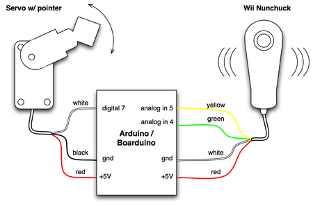
First of all I got to thank a few people that before me putted their experiences online. That simple project is based on the code and infos found on the following pages:Read wii nunchuck data into arduinohttp://www.windmeadow.com/node/42Boarduino, Wii Nunchucks, and Servoshttp://todbot.com/blog/2007/10/25/boarduino-wii-nunchuck-servo/Here's a simple schematics on how to connect the servos and Nunchuck to the Arduino. Servo's pins are 6 and 7.
boarduino-nunchuck-servo-450.png
The code is here.You can find more infos about the code in the two links I mentioned before, but feel free to ask.The only section you should customize to adapt to your servos an need is a list of variables:refreshTime (set to 20) - minimum refresh time for servo pulseminPulse (set to 1000) - minimum pulse value for servo 1minPulse2 (set to 500) - minimum pulse value for servo 2dtime (set to10) - delay (in milliseconds) for each looppwbuffsize (set to 10) - how many values has to be buffered and the averaged (that's the same value for both servos)Next post will be regarding the evolution of that interface: changed camera and servos with a smaller and ligher one (this one) and made the connection between the Nunchuck and the camera, wireless.Hope that can be helpful and feel free to ask anything about that.Thank you and ciao,Andrea
Read more…
3D Robotics

BlimpDuino version 2 now done

We're racing to get ready for the FIRST Robotics Championships in Atlanta next week, and the second version of our Arduino-powered RC blimp mod kit is coming together nicely. We moved to a two-sided board and integrated our custom IR direction sensors into the main board. Above is what it looks like now, in the toy RC blimp gondola that we have lobotimized: And the same side view of our previous version, which had the IR sensors on a separate daughterboard on a stalk:

We saved about 10 grams and a huge amount of fiddle factor by integrating the IR sensors. I moved the electronics to the outside so you can get to the on-off and reset switchs and programming port. But for the next version I may just leave the LEDs, switches and sensors on the bottom side of the board and move everything else inside for neatness. We may be able to save a few more grams by switching to the Maxbotix ultrasonic sensor instead of the Ping ))). Right now the whole blimp gondola, with all electronics and battery, is just over 80 grams. I doubt we can bring that down much more than another 10 grams, even with surface-mount components and a smaller board. But it doesn't really matter much, since we have plenty of extra lifting capacity with the 52" envelope we're using. Here's the latest version of the Arduino code, which now flashes the LED a set number of times to show you which direction the IR sensors see the beacon coming from (useful for debugging).
Read more…

Missouri S&T UAV Team - Autopilot Tuning

On Saturday (April 5th) we flew the airplane for the first time with the autopilot since it got the new wing. But before we went out to the RC airfield we had to physically install the autopilot in the fuselage, which went well. We then performed all of the flights necessary to tune the autopilot in HIL (Hardware In the Loop) simulation mode.

3689300785?profile=original

Using HIL simulation allowed us to all to get a better of idea of what we had to do once we got out to the airfield. In the end performing the HIL simulation in the lab saved us a lot of time and allowed me to get more familiar with tuning the PID control loops for the autopilot. Previously we had not used the PID window in Virtual Cockpit, but after using it in the HIL simulation it proved to be invaluable for properly tuning the autopilot, it allows you to see the actual, desired, and effort of a certain control parameter (i.e. pitch, roll, yaw, altitude, etc.). Previously we had had issues seeing a change in the behavior from the ground after changing a certain PID gain.On the first flight soon after takeoff the aircraft became unstable and began to become uncontrollable and began oscillating wildly, fortunately our pilot Kyle was able to get it back on the ground without any damage. It turns out that our CG was too far aft, but after adjusting the CG we were able to continue with testing. Using the PID window and the having performed the same process of tuning the autopilot in HIL mode, the first few flights went quickly and we were able to quickly tune the level 1 control loops within two 15-minute flights. A graph of the autopilot’s roll performance is shown below, ideally the two lines should match, and they are in fact very close.

3689300827?profile=original

We then moved on to the level 2 control loops (i.e. pitch from airspeed, pitch from altitude, airspeed from throttle, etc.). These were slightly more difficult, and took several passes over the airfield to complete, but we were able to get them tuned to a reasonable level. The ability of the autopilot to maintain a constant altitude is shown below, there are slight oscillations in the altitude (+/- 3 meters), these are reasonable, but might be improved at a later time with more tuning.

3689300696?profile=original

Just as my laptop battery was about to give out we moved on to the final flight of the day. The purpose of the final flight was to verify that the autopilot is able to navigate accurately and safely. The first test was simply placing a loiter waypoint above the center of the RC airfield; although there were some oscillations in altitude, the overall performance was quite good (note the 4 m/s wind speed).

3689300798?profile=original

The final test was to create an oval over the airfield that the UAV would have to navigate. The first time around the circuit the UAV did not adhere to the waypoints too strictly, but after adjusting some of the navigation parameters the performance was significantly improved (see image below). After completing these flights the telemetry was reviewed and we were better able to analyze the performance of the autopilot and its navigation.

3689300844?profile=original

Overall the testing went well and we were able to tune the autopilot control loops better than we had previously been able to with the old wing, this is most likely due to our use the PID window and the HIL simulation which allowed our time at the airfield to be spent much more efficiently.For more information or past posts visit our site: www.aessuav.org
Read more…

Motor Glider UAV project

Hi all,this is my first blog and I wanted to share that experience with you as most of my projects are about UAV and robotics.
First of all I got to thank the whole "DIYDrones" community that gave me a lot of informations and ideas in the past. And continues but... now I think it's my time to share my findings while developing my "ideas".
I usually work with the Arduino open platform but lately I've been working with Gumstix hardware and I have to say that they are both great "technologies" to start you project with.
My actual project is to develop and autopilot for my Omei 2000 motor glider. That's part of a series of projects, all related.
3689300805?profile=original
In my project the authopilot module will: stabilize the flight, follow a GPS programmed path and come back home, send informations to the base station, etc. Nothing particular, nothing that you guy haven't done already. And what about sensing thermal and trying to "follow" them authomatically to increase authonomy and flight times? I've been thinking about putting very light solar panels on the wings to "recharge" batteries while flying. But I'll write more on next posts.
I'd like to add something more like a pan&tilt camera, radio linked to virtual glasses with head tracking, so that has you move your head the camera moves accordingly. About that I've already made some test a few months and probably my next post will be about that. I got a video and Arduino code to share.
Personally I flew with paraglider, and now I fly small and light airplanes and motor hang glider. Can't stay too much away from it. But lately (let's say one year) I don't have much time for flying and that's where it came the idea of starting with RC flight.
That's all for now. I only forgot to say... forgive me for my mistakes in english as it's not my mother language. I'm italian. Thanks.
Thanks. A presto,
Andrea
Read more…
http://www.eetimes.com/news/latest/showArticle.jhtml;jsessionid=GW53B4ZAN3QNAQSNDLSCKHA?articleID=207001827So for UAV booms to become the dot com booms of the future, sensors need to cost under $1. Basically another year, another wave of startups, but no affordable motion sensors. Interestingly, this year they're not making the mistake of attacking gyros like Invensense did. They're focusing on accelerometers, not saying they're accelerometers, and selling the application rather than the measurement.The artificial neural network experts category on Craigslist is still a few decades off.
Read more…
3D Robotics

[UPDATE: after legal advice from LEGO, LatteBox has now changed its case design to remove the LEGO Technics holes, which you can see in these pictures. The new case is shown at the bottom of this post.] What got me into this whole UAV thing a couple years ago was the crazy idea that I could combine my love of LEGO Mindstorms robotics with my interest in RC planes. And thus was born the first Lego UAV. But to be honest it's a bit a kludge, given the constraints of the huge Mindstorms motors, and the gearing apparatus I needed to get it to drive just one control surface, the rudder. (Everything else is controlled by the off-the-shelf FMA Co-Pilot). That's a shame, because the Mindstorms NXT CPU module is a very capable ARM7 processor with Bluetooth, I2C ports, a display screen and a great set of programming tools, ranging from RobotC to LabView. And the available sensors include everything you'd need for a proper UAV, from 3-axis accelerometers to gyros, compasses, even pressure sensors. The only barrier to it being a real-world robotics platform is the motors, which basically only make sense in a Lego context. If only there were a way for NXT to drive regular RC servos.... Now there is. This week I received the new Lattebox NXT servo controller, which was first discussed here on DIYDrones a few weeks ago. It's a brand new product from a Taiwanese company, so it's still a little rough around the edges in terms of documentation (and I've got some doubts about whether the use of the Lego connecting holes is actually legal!), but the hardware build quality is excellent and it looks really powerful. Here's what comes in the box:

That's an I2C multiplexer, which connects to the NXT CPU (and allows other I2C sensors to be connected) and a servo mulitplexer, with ports for up to ten servos. (You can add more of these boxes to a total of 160 servos--all independently driven by one NXT!). The I2C multiplexer costs $140 and the servo driver is $60. Both are quite small, around the size of a standard RC servo or RC receiver. The C code to run them is available here. I haven't had a chance to put it through its paces yet, but I'm pretty jazzed about what I've seen. But at this point I need to disclose that there is a competitor to this product that I've been beta testing for the past few months (but can't yet talk about). Indeed, I've built a whole new UAV around this other NXT-to-servo hardware, which I'll be showing at the FIRST Robotics Championships in Atlanta on April 16-18. The ability to use the Mindstorms controller, sensors and IDEs for proper aerial robotics is nothing short of mindblowing, and I can't wait to unveil my bird then. In the meantime, here are some more shots of the LatteBox device.

I2C mulitplexer

The servo driver board, out of its case.

Back side of the servo driver board

Both together...

[UPDATE: This is the new case, with the LEGO Technics holes removed. The case shown in the previous images are no longer available. If you order the product, you will get the case here, not the ones shown in the images above it!]
Read more…

Hi res daylight

Had enough daylight to get 1/400 ISO 80 out of the A560. It definitely does a better job with those 7 million pixels. 1/400 is probably just below the minimum shutter speed. In dead calm air, the camera was much more stable. With the current yaw program & the instability of 1Hz GPS, only had enough battery power for a 270' turn on autopilot.
Read more…

This is my current Project-Plan:Stabilize nick and roll of my Walkera Dragonfly DF36 with Arduino and provide an easy interface to the RC servo output.(read acceleration data from a Wii Nunchuck and pulse servos to keep horizontal position)First steps:- Hardware setup- Create a starting sketch and develop it based on libraries and functions.Thanks to everybody who is developing nice stuff for Arduino (it helps me a lot when I get stuck)This is my Blog where I post all my findings:http://www.vodkadoctors.at/captFuture/blog/
Read more…

New Wing for Missouri S&T UAV Team

20080320_5359R.jpg

Sorry about the lack of updates, we will be updating more frequently now. The first update being that we completed the new wing and completed the first flight with the new wing and it performed very well even in windy conditions. Unfortunately there are no pictures of the actual flight but here are some pictures of the new wing on the airplane. This new wing is significantly stronger allowing us to carry our large payload, it also has less drag allowing us to fly at greater speeds.Although you can’t see from the picture above the entire trailing edge consists of the control surfaces for the flaps and the ailerons, we plan on using the flaps during landing to allow us to land at slower speeds.We have also been working on the onboard computer for the airplane, below are some pictures of it and the new enclosure that we had rapid prototyped out of polycarbonate using the facilities on campus. The onboard computer is a single-board-computer (SBC) with a 1.8GHz Pentium M processor, 1GB of RAM, and 4GB of flash running Ubuntu Linux. This computer will handle all of the image acquisition and some or all of the image processing.

20080326_5886R.jpg

Since we have the UAV in flying condition again we will be slowly integrating the all of the electronics into the actual airframe and there should be more frequent updates now that we will be back in the testing/development phase.For older posts or information about the project please visit www.aessuav.org
Read more…
3D Robotics
The Australian Research Centre for Aerospace Automation has announced the second year of its amateur UAV contest, called the Outback Challenge, which will be held on the 23rd-24th September 2008, in Kingaroy, Queensland. There are three categories: 1) A remote operation challenge (fly by video downlink only) that's only open the Australian High School students 2) A autonomous UAV target spotting and package delivery challenge (find a dummy representing a lost hiker and drop a water bottle) that's open to anyone. 3) A documentary filmmaking challenge for any of the above teams to make a short video about their entry. Last year the contest was won by a California team from Dionysus Design, although no teams actually finished the challenge (wrap-up video here). This year the competition is sure to be much tougher. Entry forms will be available next month.
Read more…

Daylight timelapse from autonomous hover

Got some timelapse of a hillside in wind. Wanted to face away from the sun this time but there was nothing to see. Note the sun reflecting off water on the hillside. These were 3k images.
Daylight timelapse from autonomous helicopter from heroine worshipper on Vimeo.Ning is the only game in town for 3k images. Had to go up to ISO 400 to get enough shutter speed to overcome vibration. Crummy camera kept going for smaller iris instead of faster shutter.

Small landing zone, but still $40,000,000 for those 5 sq ft.
Read more…
3D Robotics

PCB fabbing advice

For those of you getting into creating your own PCBs, here's some quick advice: We use the CADSoft Eagle software (free version can handle up to two PCB layers). It's powerful but pretty hard to learn. For easier to use (albeit more limited) software, you might try PCBArtist (also free). I'm a newbie, so I use PCBArtist. Jordi is an old hand, so he's now using the pro version of the Eagle software. Once you've designed your board you need to send it off to be fabbed. Here's some advice on the best companies to do that, from a friend, a pro in the industry: "Most of my fab is done by 4PCB. They have good service, online-quotes, fast turn-times, web-tracking and good prices for rectangular any-layer boards. $500 free for first-time customers. For extra cheap small quantities of 2-layer rectangular boards without soldermask or legend: BarebonesPCB (they are actually a re-badged 4pcb). For odd shapes, cut-outs or gold plating, I use: BACircuits. 4pcb can do it all, but they charge a hefty premium for non-standard stuff."
Read more…
3D Robotics

New double-sided BlimpBot board!

Our progress towards a $79 UAV mod kit for toy RC blimps is going well. We've now got a much better, two-sided PCB board that we're having fabbed. It's smaller, has more features and now integrates the IR sensors on the same board (Eagle schematic here; mask files here) The board is an Arduino (ATMega168 CPU) clone at heart (we call it "Blimpduino"), with: --Four motor drivers (two 2-motor chips) --Four IR sensors and associated supporting components --Ground-based IR beacon --A choice between rechageable (more expensive) and non-rechargeable (cheaper) Lithium batteries --Port for Ping))) ultrasonic sensor --ISCP and FTDI programing ports Pretty cool--a complete blimp autopilot and sensor package (with one ground beacon) for $79! Don't place your orders yet--we've still got a lot of sourcing and testing still to come--but I'm looking at having it ready for Christmas ;-)
Read more…
3D Robotics
We've been following the Paparazzi autopilot project with interest for several years. It's a European open source technology initiative that has created both thermopile (infrared sensor) and gyro-based autopilot hardware, along with quite sophisticated software to run it. But the problem to date is that the only way to use it was to fab your own PCB boards and otherwise built the hardware from scratch. We're all about DIY here, but that's a bit much for most people! So I was delighted to learn last week that you can now buy the Paparazzi hardware pre-made, either as fully-populated PCB or a bare board to solder yourself. That will significantly expand the potential audience for Paparazzi, which is a great thing. To mark this moment, I asked Martin Müller, who was part of the team that gave this awesome demo of global coordination of Paparazzi flights, to explain more about the project. Q: First, can you tell us a little about yourself? As a day job I work as an electrical engineer for a big automotive supplier here in Germany. We do car navigation systems. I have been building RC aircrafts since being a kid. It is amazing what is possible today - much more than what I always dreamed of! Q) Who are the core team now developing Paparazzi? The Paparazzi project started at ENAC in Toulouse, France in 2003 with Antoine Drouin and Pascal Brisset. Later in 2004 people in Germany and Arizona built Paparazzi systems and contributed. Since then more people joined. Some names and pictures can be found at the end of the 24C3 presentation. We try to meet about twice a year, usually at the location of a competition. Q) In broad strokes, what makes Paparazzi special? What was the motivation for developing it? The idea was to build an autonomous aircraft to be able to take part in competitions. Over the years the various competitions pushed the technology forward. The special thing about Paparazzi is that people from diverse fields come together to work on making very small autonomous aircrafts. There are aerodynamics people good in building airframes, flight control, software, electronics and not to forget RC control. Q) Where is Paparazzi going next? The next competition will be in Braunschweig, Germany this summer. Work is in progress to get the quadcopter fully autonomous. Also scientific meteo applications will be important this year. Q) Paparazzi is based on a thermopile sensor (as is the commercial AttoPilot). What are the pros and cons of that, as opposed to gyros and accelerometers? Thermopiles give you an excellent way of flying autonomous aircrafts. They give you an absolute reading which keeps the whole control simple. We have flown in mild Europe, the deserts of south-west US, tropical rainstorms in Florida, near a glacier on Iceland, hot northern India and last week a Paparazzi equipped team collected meteo data by flying from the helicopter deck of a Norwegian coast guard icebreaker. There are limits for thermopiles but they usually do not hurt you. As a hobbyist you do not want to fly in bad weather anyway. For commercial usage - if there is thick fog the on board video camera can not see anything anyway. It will not work in fog or inside clouds and there needs to be some temperature difference. Generally the limit where thermopiles do not work any more is far more towards bad weather than what you would think. Q) Finally, can you describe the set-up and organizational challenges that were required to pull off your amazing CCC demo? The two way telemetry stream was transferred through TCP/IP. Off-the-shelf video software was used for the on board pictures. Some special efforts had to be done to be able to get a connection to the German airfield as we only had a cellphone which was very well shielded by the network firewall. One team each was waiting at the fields in France and Germany, ready to take off and fly the mission!
Read more…