I'm sorry for the delay, this episode was recorded by Chris' phone and my laptop and the background noise required a lot more edits than usual. Jack Crossfire will be pleased to note that I found the source of the reverb and confined it to a theoretical vacuum. Of course the background noise probably didn't help (it's better at the end) but the quality should be up from here on out!
Finally, the article I wrote is out in the May 2010 issue of Circuit Cellar Magazine. Unfortunately I have yet to get my hands on it. From http://www.circuitcellar.com/magazine/; it's $2 to buy or go to Barnes and Noble and get yourself a copy of the magazine.
The FreeSpace IMU: A Quaternion-Based Algorithm for Attitude Estimation by TJ Bordelon
An unmanned robotic vehicle requires a working inertial measurement unit (IMU), which outputs an estimation of the attitude, or orientation, of a vehicle in 3-D space. For attitude estimation, you need MEMS sensors (e.g., gyros, accelerometers, and magnetometers) and a sufficient algorithm to “fuse” them together. This article covers a simple quaternion-based algorithm for an IMU project. p. 14
"The Indoor Aerial Robot Competition was held at Drexel University last week, featuring a bunch of the chubbiest fully autonomous robots you’re ever likely to see. The bots were tasked with locating and retrieving small boxes, and doing search and destroy on hapless red balloons."
We've had the ArduPilot 2.6 code in the repository for a while for alpha testers, but it now seems solid enough for wider testing. So it's now available in an easy-to-use zip file for everyone to download and try. Doug Weibel, the main author, has described many of the new features here, but here are some more highlights:
New Features of ArduPilot 2.6:
Supports IMU or thermopiles
All-new control laws. PI and D for all functions
Two fly-by-wire modes: A (with airspeed control) and B (without airspeed control)
Designed for ArduIMU code 1.7 if you're using the IMU (upgrade if you haven't already)
Support for absolute pressure sensor and magnetometer add-ons to IMU
Optional performance reporting; sends IMU quality data (gyro saturation, etc) to ground station
Experimental support for autonomous takeoff and landing!
Some of this is documented in the code and the configuration comments. I'm in the process of updating the manual to reflect all the 2.6 changes, so please be patient for the next few days until I'm done.
This month's MAKE magazine is focused on RC and is especially good. The cover story is an Arduino-controlled RC lawnmower that the guy is converting to autonomous control with ArduPilot, and there are a few other ArduPilot mentions in there (plus a little contribution from me on interfacing RC with computers). Read more…3D Robotics
I'm partial to the STM32 (ARM CORTEX-M3 based uController) line of uControllers, not only for their hardware mul/div instructions, but also for their ability to have the ADC converter continually scanning and pushing to memory its conversion results from a series of analog devices.
Now, it looks like STMicro has a gamer development board, complete with five ST sensors – a 2-axis roll-and-pitch gyroscope (LPR430AL), a single-axis yaw[3] gyroscope (LY330ALH), a 6-axis geomagnetic module (LSM303DLH),a pressure sensor (LPS001DL) and a temperature sensor (STLM75). All the sensors and the AHRS algorithm are managed by an on-board STM32 microcontroller. The module, which comprises a 4x4cm evaluation board and all the necessary firmware and software, will be available for volume orders in Q2 2010.
It also runs a sophisticated sensor fusion algorithm(Attitude Heading Reference System) to provide static and dynamic orientation and inertial measurements.
In an article entitled "The Rise of the Robo-Fighters", Britain's Daily Mail newspaper discusses us:
"The website DIY Drones is a thriving community of do-it-yourself drone builders and operators, building drones that look eerily similar to - or are copies of - the weapons employed currently by the West. For a terrorist, or a lone psychopath, the idea of a vehicle that could launch, find targets and attack autonomously must seem like the ultimate risk-free weapon - a suicide bomb without a suicide bomber."
What's troubling about this is the notion that "drones = weapons". But until the regulators open up national airspace to more civilian/commercial use that shows more peaceful use cases, I suppose this is going to be something we're going to continue to have to fight/educate against.
[Thanks to Gary Mortimer for the find. Photo taken from the article]
APM 2 is an open source, Arduino-compatible, pro-quality autopilot. It is the most advanced IMU-based open source autopilot available today, and provides an entire UAV control system with scriptable missions with 3D waypoints, in-flight uploading of commands and powerful ground station software.
APM 2 supports any kind of of vehicle with a one-click change of code. Available code include ArduPlane (fixed wing), ArduCopter (rotary wing), ArduRover (ground vehicles) and more.
You'll also need a at least a five-channel RC radio setup, a soldering iron, a mini USB cable and of course something that flies! (We're partial to the SkyFun delta wing (right) and Bixlee 2 powered glider (left) or its equivalents ourselves).
Note: ArduPilot Mega requires no programming, but it's open source and you're welcome to modify it if you'd like. If you are going to play with the code, you can use the free Arduino IDE to edit and upload the code to the ArduPilot board.
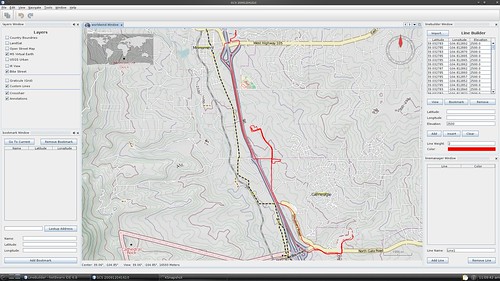
Some more progress on the GCS. I integrated a line builder and line manager. The line builder contains the editor to edit GPS coordinates of the line, as well as options for line thickness and color. The line manager imports these coordinates as a set, and given a name. This clears up the line builder, allowing multiple lines to co-exist.
The Line builder can import a list of GPS coordinates from a text file with the format: lat lon lat lon ...
I plan on adding a 3rd dimension, but i don't yet have a barometric pressure sensor.
This is zoomed in to show the Open Street map layer.
The line appears shifted from the road, but it is really aligned. The line right now is at an elevation of 2500 km, so the shifting is due to the perspective distortion. Any lower, the line disappears into the ground (the globe has elevation data). I need to figure out how to have the line at ground level.
10A @11.5V for a speed of 5.6 km/h is lousy. The same speed with 5.0A would be OK. This benchmark was set by the Firebrigade-ship, but the catamarane had a much better straight-line behaviour.
OK, let´s improve the catamarane...
In the long winter evenings i googled a lot about catamaranes. Somebody had posted a comparison between different hull shapes / cross-sections. The one with the triangular cross-section as i was using, proved to be the worst in terms of drag. But it was the best in terms of straight-line behaviour and ease of construction. The best in terms of drag was an elliptic shape. Now i knew, where i was.
There are also dxf-files available. A colleage of mine is a specialist for 3D CAD design. I gave him the dxf-files and he made a 3D model of the hull out of the DXF-files. (Thanks Matthias)
But how getting a hull from the plans with the least effort?
diy-store -> Styrofoam with 100mm thickness --> some cardboard --> 14 cross-sections of the hull printed on paper --> some double sided sticky tape --> a hotwire styro-cutting assembly and three evenings when my wife had to watch TV lonely.
One of the hull-segments is the solution to the "guess-what" picture of the last episode.
This are the middle segments, stacked up.
All 14 segments (each with a thickness of 100mm) were glued together with styro-glue. A little bit sanding and the hull was nearly finished.
The glued segments, before the coating...
To add stability, the hulls were coated with a thin layer of fiberglass and epoxy.
The coating - and sticky fingers...
To connect the two hulls with a styrofoam-board that serves as a platform for the superstructures i used styrofoam screw-anchors and M5 Screws, that were epoxied and glued into the top of the hulls prior to coating.
The styro screw-anchor
To give it a real good finish there had to be much more sanding, priming and painting, but as already mentioned earlier, patience is not one of my strenghts, and so i decided to bring that provisional assembly into the water as fast as possible.
This construction is far from being perfect, but to prove the concept it was OK.
The first launch...
The first launch:
Yipee! I have invented the catamarane-oscillator!
The cat oscillated, but found its waypoints. On the first run...
The second one with decreased P ended up in my first swimming exercise in this year. It was still oscillating, but it did not manage to find anything. The problem seemed to be the lateral stability of the ship´s aft. The new hull had problems with his butt! Back at home i added fins on the backside of the hulls. The size had a triangular shape and went about 100mm below the waterline.
Back to the lake...
The lateral stability was much better, when manually testing it by shifting the ship left and right.
Launch...
Swim!
This was too much of the good thing. The ship went off with absolutely no oscillations, it seemed that it sits on on rails. Finally it crashed to the shoreline after having drawn a very wide circle. The crashpoint was 2 meters away from a russian-immigrant fisherman, who is always there when i had unlucky experiences. I like his comments. "Ahh, new ship ey!", "Ahh, better ship now (grin)". The propeller managed to wrap the end of a small branch around its shaft two meters away from the shoreline. I took off my trousers and waded into the swamp to get it out of the water. Must have been a curious looking picture, because i went to the lake on my way back from the office: A man standing in his undertrousers in a lake with shirt and tie, holding a catamarane in his hands, discussing with a russian-based fisherman about fishing spots.
As a next step, i stripped the fins to one third of their original size. And now it was perfect.
No oscillations, straight line...
The two fin sizes together ( i re-glued the cutted segment to see the difference)
What a difference some square-centimeters make!
The new Data:
current: 5.2A @ 11.5V
speed: up to 8 km/h
Thats all till now, time-lapse is over, with episode 11 we have reached the real-time.
Let´s see what the future will bring!
What about starting a colaborating project for UAVs (Unmanned Aquatic Vehicles) on this site?
(The start will be the finding of a better abbreviation...)
Here's an excerpt froman articlein Willamette Week, a Portland weekly. It's a mix of well reported details about the founders and clashes within the company, plus some clueless stuff about how drones are evil and kill people (Insitu UAVs are actually unarmed, something the reporter seems not to understand). Read the comments, too.
"With a successful 1998 flight from Newfoundland to Scotland on a gallon and a half of gas, Aerosonde became the first unmanned plane ever to cross the Atlantic.
The publicity stunt captured headlines. But McGeer never managed to sell more than a handful of the drones—despite some enthusiastic support from within the bureaucracies of national weather services around the world, they could not be swayed into buying.
“That was life,” von Flotow says. “When you’re running a little garage business—and there’s many such businesses—you’re always chasing the dream, and the dream never quite makes it into your grasp.”
The next opportunity at McGeer’s door came from the tuna industry, of all places.
Tuna companies track schools of the fish using helicopters. It’s expensive and dangerous work, and McGeer was told the industry would pay for a plane that could launch from a boat with a camera to do the job.
McGeer set to work designing a new unmanned plane he called the SeaScan.
Again with help from von Flotow, McGeer and five employees worked at a dizzying rate of invention to master the biggest technical hurdle—launching and retrieving the plane from the deck of a ship.
They came up with a 14-foot catapult that slingshots the plane into the air at more than 50 mph, then spent years perfecting and eventually patenting the so-called “sky hook” landing system, which lets the plane fly into a rope suspended from a pole.
With a maximum speed of about 90 mph, the SeaScan was the first unmanned plane able to deliver high-quality video footage. Like the Aerosonde, however, the SeaScan never found a successful market.
This time, it was terrorists who got in the way.
Just as the SeaScan prototype was being completed, the 9/11 attacks came. McGeer had already been in contact with Boeing and others in the defense industry for the better part of a year about possible military uses for SeaScan.
Now they left the tuna industry behind and went into high gear. But not without reservations.
“There were plenty of people who weren’t comfortable. But we went along with it,” McGeer says. “I took an ends-justify-the-means argument—that taking this money would allow me to get into the civilian market. But I was wrong. That never happened.”
Insitu underwent other rapid changes in 2001. McGeer called in Steve Sliwa, a friend he knew from their undergrad days at Princeton, to turn Insitu around. And coincidentally, the day before 9/11, the Boeing Co. first agreed to invest in Insitu."
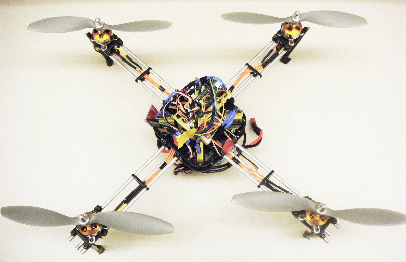
For a class project, we built a quadrotor using the Sparkfun Razor IMU and a Atmega32U4 running the PID controls. After about a month of work, we successfully flew it with great results (alright, it wasn't super stable, but it stayed up!). Check it out at www.wyvernupenn.blogspot.com.
The 1st flag to be lifted autonomously suffered an acidic fate...
when our field battery fell over & leaked acid on it. Lead acid batteries do pour when they fall over. It was never much use since crashes would always end a campaign before the batteries ran out.
Rather than fly the melted nylon & cause a hole to form, decided to put it down. All cleaned off, tried to give it to the Air Force, whose answer was yet another FUGGEDABOUTIT.
Marcy 1 & 2 examine the melted masterpiece.
MARCY 1 RPM INCREASE
Marcy 1 began a campaign to increase RPM, abandon thermopile attitude sensing, & become passively stable. Thermopiles & active stability may return in a large scale copter.
It's been disasterous. The fatter wing seems to require too much balance beam inertia to stabilize. May have to go to with a long, thinner wing.
Have a flight over Livermore.
Never got Major Marcy but still got some emotional support in the end.
The best explanation for why Major Marcy never wanted to see us in real life was if a heroine knows someone's attracted to her image online yet has no confidence in her beauty, she may be afraid of losing the illusion. It's been very consistent for years.
She only talked to alpha males but demonstration of lower value, overwhelming surplus of men in Silicon Valley, & our crazy gender views didn't explain everything.
Now a still photo movie.
MARCY 2
Been a few weeks & still stumped over why Marcy 2's radio won't initialize on the golf course but will initialize in the apartment. It's very common for circuits to fail on the golf course because of the harsh environment, nothing specific to Marcy class vehicles. Focusing on weak solder joints & floating solder balls. Sux using custom electronics for Mar vehicles in a sea of off the shelf parts.
Marcy-2 radio test.
It's heading towards just insulating the board & keeping it warm. The traces are probably too long & close together for the environment.
PCB Boards are Cool, but the Holy Grail for robotics are the Kapton Flex Circuits which are both wire and circuit in one.
Using This Material, I was able to CNC a single-sided SMD circuit which is thin and flexible - though not quite Kapton :-(
For lightweight circuits that fit into odd shapes (like fuselages), etc, this is a process that can't be beat. You could probably use a chemical etch, but the CNC does the routing and cutout with the same tool.
First Design in Eagle then export in PCB-GCODE. I used 20mil spacing in eagle and a 16mil tool in gcode with a 3mil default (offset). I glued the scissor-cut material to a thicker PCB with spray glue, then held it down with clamps. It is critical to get the working surface flat (which took time and error).