All Posts (11086)

Sort by

For a long time DJI has sort of forgotten the commercial market, apart from filmmakers.

With the announcement of the DJI A3, however, it is offering a very compelling product.

3689689048?profile=original

Here is a list of features I think are important for the commercial market:

  • Triple redundancy, both in GPS and IMUs. Pixhawk won't arm if IMUs mismatch, but if one fails in flight how do you know which reading is correct? (I would like to see some CPU fault tolerance since NAZAs have been known to freeze causing crashes)
  • Motor fail tolerance. I am guessing this also has a lot to do with ESCs that actually give feedback to the Flight Controller as opposed to only reading a PWM input.
  • RTK GPS support (this one is already supported on Pixhawk so I guess Pixhawk wins the battle here, but we'll see how well it works)
  • Lightbridge 2. High bandwidth, low latency, digital communication. (I don't know why they are also offering Datalink Pro with <1Ghz frequency when Lightbridge is so advanced already.)
  • Ground station support. (This one is a must, but was almost forgotten with the A2 and the outdated DJI Ground Station for windows and iPad.)

Now I am in now way affiliated with DJI and I am actually a supporter of Dronecode and Open Source in general.

However, this announcement makes me rethink whether Dronecode based drones will continue to be the best option for any business operating drones.

I, personally, have been using a Phantom 2 for surveying for 2 years now and have sold mods of it for surveying work and they have worked great (not that I had problems on the Pixhawks either). But I think the refinement and ease of use will be really compelling for anyone except the OS fans like us. 

Now, of course the main thing going on for Dronecode and 3DR, and the reason I won't buy another Phantom, is the versatility of Open Source based drones. But if (big IF) DJI gets a decent SDK they might be a very solid option even for people with custom needs.

I am sure we will see some serious competition soon between 3DR and DJI which I think will benefit everyone, 3DR will have to keep up with the relentless upgrade path DJI is taking right now. I would be quite nervous if I were 3DR, since matching the technology used in DJI products will require vasts amount of time and money (the Lightbdridge alone is quite remarkable with OFDM) and they don't have the super profitable consumer products DJI has.

I do wish they'll keep up since they (together with this community) make the drones I've had the best time developing with.

Read more…
100KM

The Perfect UAV Mapping Camera

3689689012?profile=original

It’s really strange that there’s been so much development in all other aspects of UAV Mapping, except one – the camera!

Currently most of us are using the Canon S100-120 or Sony Nex7 etc, running custom firmware or tricky wiring and triggers to fire the shutter in flight.

So over the years I’ve been working on a wish list of what my perfect UAV mapping camera would be like and decided to post it here, maybe someone knows of such a beast somewhere or can add to the wishlist and perhaps a manufacturer can build one for us!

For NDVI I’m using Tertracam’s great cameras, which are perfect for UAVs, so most of these points already exist for NDVI cameras.

  • A light case, perhaps plastic
  • A fixed 9mm lens, no zoom
  • No flash
  • No LCD
  • Mounting holes
  • Optional battery (less wires) or external power (lower weight)
  • A built in intervalometer
  • An external GPS unit
  • A very large optical sensor – 1” or more for 20-30M pixels
  • A way to trigger the shutter externally (from APM) for those that prefer this method
  • 1/2000 sec shutter at a low F stop
  • Permanent infinity focus
  • Replacement parts – i.e. lens, board, case in case of “intendents”
  • Sync on-board clock with GPS

Is there such a thing? Do you have any more to add to the wish list? Can somebody build this for us please?

Read more…
3D Robotics

3689689035?profile=original

At a developer conference in China last week, Intel gave a sneak peak of its forthcoming drone and robotics development boards. The drone board, called Aero, is designed to compete with Qualcomm's Snapdragon Flight board (Intel, like Qualcomm, is a member of Dronecode and the Intel team has ported to the APM code to their X86-based platforms). 

From PC World:

A major element of the developer boards is the RealSense 3D camera, which will ship with the kits and help the robots and drones navigate and avoid obstacles. The depth-sensing camera can recognize items and determine the size, shape and contours of objects. For robots, the camera provides computer vision, which is analogous to eyes in humans.

The Robotic Development Kit will be priced at $249 and will ship later this quarter. It has a credit-card-sized board from Aaeon, which is equipped with an Intel Atom x5 Z8350 CPU, an internal Intel HD 400 graphics processor, 4GB of DDR3 RAM and 32GB of storage. Other features include an HDMI slot, Gigabit ethernet, two USB 2.0 ports, a USB 3.0 port, a camera interface and an eDP (embedded DisplayPort) slot to connect a display. It also has a 40-pin GPIO (general purpose input-output) slot to hook up add-on boards that may have sensors or other components.

The kit will ship with Ubuntu Linux but will also support Windows 10 and other versions of Windows.

The Aero Platform is a “ready-to-fly developer platform,” an Intel spokesman said in an email. It has an Intel Atom x7-Z8700 processor, DDR3L RAM and flash storage, and it will run a version of embedded Linux. Full details and price aren’t yet available, but it will ship in the second half of this year.

The hardware is part of Intel’s effort to diversify outside PCs into new areas. It’s also an effort to provide do-it-yourselfers with the resources to develop a wide range of gadgets, appliances, and smart home and industrial equipment.

3689689175?profile=original

Read more…
3D Robotics

From the Freshwater Trust:

The Freshwater Trust has partnered with Portland State University’s Sustainable Water, Energy and Environmental Technologies Laboratory (SWEETLab) and Oregon State University (AIS Lab) to test how unmanned vehicle systems (UAS), commonly known as drones, can help monitor the health and growth of streamside forests.

A team of engineering professors and graduate students will spend several days in March flying UASs over a river restoration site in Oregon’s Willamette Valley, collecting data on forest density and species height.

The results of the data collection will demonstrate if UAS technology can be used to help The Freshwater Trust cost-effectively and accurately monitor river restoration projects, and also help further develop the SWEETLab’s monitoring techniques for an ongoing land-use project in Rwanda. The Freshwater Trust employs teams of scientists to count trees and monitor its work restoring vegetation to riverbanks.

“We plant thousands of trees along Oregon rivers every year,” said Monique Leslie, habitat restoration project manager for The Freshwater Trust. “We typically monitor these projects over 20 year periods, which can take a lot of field time and effort. Long-term monitoring is essential to assess the effectiveness of our projects, and we are very interested in figuring out how technology can help us streamline our work and allow us to maintain high quality data.”

The Portland State SWEETLab works with academic, industry and nonprofit partners around the world to develop and implement technologies for the support of life in remote environments. The Oregon State AIS Lab conducts UAS flights for a variety of applications including agriculture, engineering, fish and wildlife and forestry.

Thousands of miles from the Pacific Northwest, the laboratory is investigating ways to monitor how forests in Rwanda change in response to nearby villages receiving high efficiency cook stoves. While counting the number of trees used for fuel is traditionally both time-consuming and costly, the laboratory has begun experimenting with using UASs to complete surveys with greater efficiency.

“In Rwanda, Portland State is in a partnership to reduce wood fuel use in households through providing high efficiency cookstoves,” said Professor Evan Thomas, of Portland State University. “If we are successful, we may be able to turn parts of Rwanda from a sink into a source for trees. Counting trees manually is time consuming. With these UAV technologies, we can fly across the country and measure tree density. This challenge is nearly the same as The Freshwater Trust’s data needs here in Oregon.”

One technology is a small quadcopter equipped with a GoPro that takes digital photographs at a high frequency, which can be compiled to create a 3D map ready for analysis of the forest density. The second is a larger helicopter that uses LiDAR, a remote sensing method used to examine and model the surface of the Earth. The information collected with these unmanned aerial vehicles will be compared to each other and the data collected on the ground and analyzed for their accuracy.

“We’ve developed one of the first operational UAS LiDAR systems in the U.S.,” said Professor Michael Wing, director of the OSU AIS Lab. “LiDAR allows us to take extremely accurate measurements of landscape features that we can use to better manage natural resources.”

In the spring of 2015, crews finished planting more than 6,000 native trees and shrubs along Cedar Creek, a side channel to the McKenzie River in the Willamette Valley. The Metropolitan Wastewater Management Commission, the wastewater utility for Oregon’s Eugene-Springfield communities, hired The Freshwater Trust and its subcontractors to restore forests along the banks of the waterway to produce shade and cool the temperature of the river. This restoration action improves habitat for native fish and showcases how a natural infrastructure solution can be used to help utilities meet temperature requirements under the Clean Water Act.

“We are trying to bring conservation into the 21st century,” said Leslie. “By using the most technology available to us today, we have the opportunity to make restoration more efficient, something that’s needed if we want a future with clean, healthy rivers. This project will allow us to understand if drones can collect the detailed data we’re interested in with the accuracy we need. It’s critical we ensure the plants we’re putting in the ground are meeting the quality standards necessary to assure positive outcomes for the river.”

Read more…
3D Robotics

State of ROS 2.0

One of the priorities of Dronecode is to integrate with other open source software communities, include Linux as the lower (OS) side and ROS at the applications layer. Dronecode is part of the Linux Foundation and the Open Source Robotics Foundation, which makes ROS, is part of Dronecode.

One of the things that has held ROS back from widespread adoption by drones to date is that it was originally designed for indoor robots with very reliable communications between nodes, while UAVs operate in a much less reliable communications environment. But ROS 2.0 has been designed to handle such distributed mobile robotics systems with less reliable communications links, and it can uses a sophisticated middleware layer that both handle non-deterministic communications links and restore communications links if broken. 

Here's an update from the ROS community on how ROS 2.0 is coming as it prepares for release.

ROS has been an enormously important resource for the robotics community. It turned eight years old at the end of 2015, and is currently on its ninth official release. As ROS adoption has skyrocketed (especially over the past several years), OSRF, together with the community, have identified many specific areas of the operating system that need major overhauls in order to keep pace with maturing user demand. Dirk Thomas, Esteve Fernandez, and William Woodall from OSRF gave a preview at ROSCon 2015 of what to expect in ROS 2, including multi-robot systems, commercial deployments, microprocessor compatibility, real time control, and additional platform support.

The OSRF team shows off many of the exciting new ROS 2 features in this demo-heavy talk, including distributed message passing through DDS (no ROS master required), performance boosts for communications within nodes, quality of service improvements, and ways of bridging ROS 1 and ROS 2 so that you don't have to make the leap all at once. If you'd like to make the leap all at once anyway, the Alpha 1 release of ROS 2 has been available since last September, and Thomas ends the talk with a brief overview of the roadmap leading up to ROS 2's Alpha 2 release. As of April 2016, ROS 2 is on release Alpha 5 ("Epoxy"), and you can keep up-to-date on the roadmap and release schedule here.

Read more…

I am happy to announce that my DIY project BBBmini won Third Prize in The SeeedStudio BeagleBone Green IoT Contest. BBBmini is a DIY Cape to put on a BeagleBone Board.

BBBmini in combination with a BeagleBone gives you:

  • DIY state of the art UAV autopilot / flightcontroller
  • Easy to build, no SMD soldering necessary
  • Free hardware, free software
  • ArduPilot flightcontroller software
  • Real-Time Linux Kernel 4.1.X or 4.4.X
  • DIY friendly connectors 0.1” pin header
  • 12 x PWM out with individual frequency for each channel
  • RC in connector for PPM, S.BUS or spektrum satellite input
  • MPU-9250 IMU 9 x DOF
  • MS5611 barometer
  • HC-SR04 ultrasonic rangefinder
  • GPS for full autonomous flights
  • Voltage and current sensing
  • I2C / GROVE connector for Status display and additional sensors
  • SPI connector for second redundant IMU
  • UART / GROVE connector for GPS
  • UART / GROVE connector for telemetry
  • CAN connector with on board CAN bus transceiver
  • USB connector used for WiFi, Laser rangefinder or cameras
  • Excellent cost-performance ratio

Best regards

Mirko

Read more…

_89282321_031922150-1.jpg

Breaking news on BBC.

Could be a first proper strike. Or not.

A plane approaching Heathrow Airport is believed to have hit a drone before it landed safely, the Metropolitan Police have said.

The British Airways flight from Geneva was hit as it approached the London airport at about 12:50 BST with 132 passengers and five crew on board.

After landing, the pilot reported an object - believed to be a drone - had struck the front of the Airbus A320.

http://www.bbc.co.uk/news/uk-36067591

Read more…

Quick tip 1

3689689060?profile=original

As you work on things or change things you will frequently have to disconnect a lot of cables. It can be confusing or a pain to remember exactly where everything connects back in.

Get yourself a pot of nail polish, brightly colored and a pack of toothpicks and use the toothpick to put marks where you need them. In fact, whether you are building quads or repairing your Aston Martin, you should ALWAYS have nail polish and toothpicks in any well stocked toolkit; you'll be amazed how handy they are.

For motor cables into your FC, for example, you can use dots to mark channel number  (As in the pic below) and this is a lot easier than trying to write the number really small with a marker or such.

For other connections, take the toothpick and run a line from one side of a connection to another so you have a quick visual reference - line up the marks and voila!!

Read more…

U-Blox M8P Integration done!

M8PDIY.jpg


A lot of actors of the L1 low-cost RTK market have been emerging these months. U-Blox plays a relevant role in the miniaturization of GNSS chips for mass-market. Drotek and U-Blox are collaborating in order to produce the most reduced RTK board.


Market has shown that there are clearly two types of customers :

  • the ones  who like plug-and-play boards, but who still like to dig into hardware/software, eager to collaborate on any aspect. This is why we have created SMARTNAV RTK (http://drotek.io/1PodT25)

  • the others who only want simple-approach and reduced-form factor products without paying any attention to technical details. This why we are integrating M8P on our boards.


For the first tests we have used our XXL board and placed M8P on it. (http://drotek.io/1SQ5hCo) This version of M8P is capable of handling both base and rover states.

drotek_xxl_top.pngdrotek_xxl_bot.png


So we configured base in order to deliver RTCM correction messages over a 433 MHz radio link and rover to receive them. These are the first results :

m8p_ucenter.png


We got to “float” position without any problem, and deviation map showed great results in this first short test!


Drotek is ready to manufacture, waiting for U-Blox first delivery! At this stage we still do not have pricing information.


Stay tuned on drotek.com !


drotek.png


Read more…

RTK Board Integrates with Autopilot (Pixhawk)

3689688885?profile=original

(Figure 1 Demonstration of Integration with Pixhawk autopilot)

Precis RTK board can be integrated with autopilots. We use the connection to Pixhawk flight control as an example. A cable is used to connect the COM1 port of Precis RTK board and the GPS port of the Pixhawk (see Figure 1). It is noticed that the GPS port need a 6pin PicoBlade connector while the COM1 port is a 5pin PicoBlade connector. The pin definition of the Pixhawk GPS port is listed in Table 1. With regarding to the power consumption, we recommend using external power sources. Please also pay attention to the baud rate setting of Pixhawk. Then you need to mount the GNSS antenna and tether the board on your vehicle. 

Please beware of following instructions when you mount the GNSS antenna to your drone.

■ Place the module on the outside of your vehicle (in an elevated position if appropriate) with a clear view of the sky

■ Distance the module from DC power wiring and the batteries by at least 10cm


Next step is setting up the Pixhawk with mission planner. Open Mission planner software and choose the right COM port on the top right corner. Choose 115200 as baud rate (default baud rate of Precis RTK board COM1 port). Then click ‘connect button’ on the right. Then it is recognized by mission planner if the GPS status becomes ‘3D Fix’ (see Figure 2).

3689688898?profile=original

(Table 1 Pin definition of Pixhawk GPS port, from left to right)

3689688938?profile=original

(Figure 2 Precis RTK board is recognized by Pixhawk and Mission Planner)

To get more info on the functions and get support for trouble shooting, drop us a mail sales@tersus-gnss.com or visit our official website www.tersus-gnss.com for the User Guide. 

Read more…
Developer

3689689108?profile=originalArticle from ZDNet.

GoPro quietly announced its Developer Program on Tuesday, as it looks to incorporate its action sports cameras into third-party products. Third-party companies have been building accessories for the GoPro over the years, but now GoPro wants to provide official support.

The GoPro Developer Program provides toolkits, technical information and support to enable companies to add GoPro camera connectivity into their products. There is a camera toolkit for iOS and Android apps to control a GoPro camera and manage media, along with a mechanical toolkit to attach GoPro cameras to third-party products.

GoPro held an event in San Francisco, California to highlight the new program, where it announced there are more than 100 companies partnering with GoPro, including brands from BMW, Fisher-Price, and Polar. GoPro showed off potential third-party integration ideas in a video showing a gesture-based camera control system.

"Over the last few years we've been excited by the creativity and enthusiasm other brands have demonstrated when integrating GoPro into their own solutions," Nick Woodman, CEO and founder of GoPro, said in a prepared statement. "The GoPro Developer Program is a way for us to celebrate the innovative work of our developer community and more importantly, help enable what comes next."

GoPro first showed its third-party support when it announced integration with Twitter's live streaming platform Periscope in January. Owners of the GoPro Hero 4 can publish to Periscope directly through the social media app on iOS.

GoPro has been at a crossroads as of late; its stock price has been hammered as it has missed sales projections. CEO Nick Woodman is working to reinvigorate the company with new products, new hires, and now support for developers.

Read more…

FLYSKY FS-I6 FLIGHT MODES/TURNIGY TGY-I6

3689687903?profile=originalI figured I'd type up the instructions for setting up the FlySky FS-I6/Turnigy TGY-I6 flight mode switches for the ardupilot manual.

l'll include a link to the video at the end as well.

You will use a 3 position switch (SWC) and a 2 position switch (in this case, SWD. You can use any of the 2 position switches, but it makes sense to use the one next to SWC for ease of reach). This will give you 3 SWC positions with SWD in it's first position and 3 SWC positions with SWD in it's second position, giving you a total of 6 positions for your 6 basic flight modes.

Click OK to move out of the home screen.

Now click your UP or DOWN button to move to SETUP.

Click OK to enter the SETUP MENU.

Click your DOWN button to move the selection arrow to AUX. CHANNELS.

3689687842?profile=original

Click OK to enter AUX. CHANNELS.


The selection arrow should be on CHANNEL 5. If not, click OK to cycle through and select CHANNEL 5.


Click your UP or DOWN button to cycle through the assignment options until CHANNEL 5 shows SWC + D (or SWC + whichever 2 position switch you wish to use).


Click OK to cycle down to CHANNEL 6.


Click your UP or DOWN button to change the assignment option to SWD (Or whichever 2 position switch you selected in the previous step).

3689687938?profile=original


Click and hold CANCEL until your TX beeps and returns to the previous screen, to save the settings.


Click your UP button until the selection arrow points at END POINTS and then click OK.

3689687967?profile=original

Click OK to cycle down to CHANNEL 5.


The arrow will be pointing at the low END POINT.

Use your UP or DOWN button to adjust this number.

3689688013?profile=original


While doing this, have SWC and SWD in their first position and have your mission planner open at INITIAL SETUP/MANDATORY HARDWARE/RADIO CALIBRATION and have your MP connected to your quad via MAVLINK. It may be helpful, before doing this to click on INITIAL SETUP/MANDATORY HARDWARE/FLIGHT MODES and write down the PWM values for each flight mode to save you having to constantly click back to it during the next step.

3689687878?profile=original

As you adjust your END POINT, watch the value of CHANNEL 5 on your MISSION PLANNER and adjust it until it falls within the PWM value required for FLIGHT MODE 1.


Repeat this step for SWC in Position 2/SWD in position 1 for FLIGHT MODE 2 and repeat this step for the remaining flight modes.

SWC Pos 1 / SWD Pos 1 = Flight Mode One
SWC Pos 2 / SWD Pos 1 = Flight Mode Two
SWC Pos 3 / SWD Pos 1 = Flight Mode Three
SWC Pos 1 / SWD Pos 2 = Flight Mode Four
SWC Pos 2 / SWD Pos 2 = Flight Mode Five
SWC Pos 3 / SWD Pos 2 = Flight Mode Six


You will need to adjust and tweak the low and high END POINTS. To move the arrow between the LOW and HIGH END POINT, move SWC to position 2 and move SWD to position 1 for low and position 2 for high, but remember to move your switches back to the correct position for whichever FLIGHT MODE you are setting once you have selected high or low.


Once END POINTS are set, click and hold CANCEL until your tx beeps and returns to the previous screen.


That's it. You should now be able to select all six flight modes using the combination of SWC and SWD.


My values for END POINTS are 88% for low and 71% for high. Yours may be the same or may need different settings. Just keep adjusting until you have the values correct.

Here is a Video for this set up procedure -


Read more…
100KM

Until now, the only way to connect APM or Pixhawk via wireless is using radio modem. Well, you can also use blue tooth but the range is very limited. It may be good for set up or so but certainly not flying if you wish to view live data. 

For long range FPV or aerial mapping mission, I use RFD 900 radio modem. It has served me well and depends on local environment, I can receive live data up to about 10 KM. It is sufficient for our job most of the time. 

The Dragon link V3 advanced system was released early this year. Beside the usual long range ( they claim up to 50 KM ) radio control, their receiver is equip with bi direction data transfer capability. Once set up, it can virtually replace the long range radio modem. Another added benefit is their transmitter has build in blue tooth so we can use our note book computer to connect with GCS such as Mission Planner or using hand phone / tablet with Tower. This is a full bidirectional connection, so we can view live data AND also upload command or flight plan. 

The bi directional data transfer feature is fantastic to me but unfortunately the earlier version of their firmware didn't help much to get thing set up. Some user had successful link it up with computer or tablet but the blue tooth connection is not reliable. I have tried earlier but no luck. 

Early this month they release a new updated firmware with lots of improvement especially the data modem feature. A user call Noircogi kind enough to post a detail set up guild in RC Groups, which is also found in Dragon Link support page. I follow each step but still can not get it connect to my computer or tablet. After a few post in RC Groups, Noircogi and other help me with some suggestion and point out some error in my set up and now I can get reliable connection. There is actually nothing wrong with Noircogi instruction, just that I misunderstand some points. Therefore I think it may be good if I can put up a graphical guild for those who wish to try.

The work flow of the set up is :

  • Connect the transmitter with computer / tablet / hand phone blue tooth
  • Connect Pixhawk telem 2 port to receiver
  • Configure Dragon Link receiver
  • Configure Dragon Link transmitter 
  • Configure Pixhawk parameter
  • Configure Mission planner parameter. 

Now, lets get start

Connect the transmitter with computer / tablet / hand phone blue tooth


 ( All italic text is copy from DL support, for which I believe is contributed by Noircogi. )  

STEP 1:    Pair Bluetooth to your adroid phone or tablet.  ( Apple NOT supported ). 
Turn your Dragon Link advanced Transmitter and wait about 30 seconds.   Go to the Bluetooth setup in your Adroid Device, and SCAN FOR NEW SYSTEMS.  The Dragon Link will first show up as a number, and then turn into " SERIAL PORT DEVICE " in about 30 seconds.   
Select the SERIAL PORT DEVICE from the list, and choose PAIR.   You will be asked for a code, enter " 0000 " for the code, and choose OK.   The device will now pair, and automatically pair whenever it sees the Dragon Link transmitter, so this only needs to be done once.   Bluetooth has a range of about 20 feet ( 7 Meters ), so your Phone or Tablet must be close to your Dragon Link Transmitter to receive its data. ( Do not confuse with plane distance, the plane or copter can be many miles away ! ).
This step is easy, once you have pair the device, go to next step.
Connect Pixhawk telem 2 port to receiver
You need to build a special cable here. using a 6 position cable, remove wire no 1, 4, and 5, cut off one end and crimped joint with female servo pin. The red wire is in pin 1 originally, I use it as pin 2 wire for visual effect.
3689688719?profile=original3689688634?profile=original
Configure Dragon Link receiver
   
On the Dragonlink Receiver GUI
Select 19200 baud for the radio modem.
Configure the pin you connected to the TX wire from the Pixhawk as "Serial In"
Configure the pin you connected to the RX wire from the Pixhawk as "Serial Out"
Don't forget to "save" and then "reboot" the RX on the main page of the RX GUI.
3689688681?profile=original

3689688745?profile=original

I set CH 5 as " Serial OUT " and " CH 6 as " Serial IN " You can set to other CH. In the PPM Channel, select 12. This step is not mention in the instruction and I was told it has to be the same number of channel in the transmitter, which we are going to set as 12 CH later. I am not using TX / RX with reference to pin number. This is because I found contradict info which confuse me. TX and RX can be either no 2 or 3. I'm sure those technical guy can easily know which is which by I rather just use number. No 1 is the outer most pin and progressively go toward the centre of the flight controller where no 6 is the inner most.

Save the setting and reboot.

Configure Dragon Link transmitter

On the Dragonlink Transmitter GUI
Main page under RF select; 12 Channels, High Bidir Bandwidth, Fastest Update-Rate
'Radio modem & Telemetry" page select; Bluetooth: Radio Modem, Baudrate: 57600
Save and reboot here too.

Re-bind your Dragonlink receiver to the new TX settings.

3689688759?profile=original

3689688780?profile=original


You'll need to rebind to transmitter with the receiver again to let the new setting come into effect. 

Configure Pixhawk parameter.

You can configure those parameter by using USB cable plug into Pixhawk or use the normal telemetry. Once connected with Mission Planner, go to Config / Tuning then Full Parameter list and change the value as listed below. 

BRD_SER2_RTSCTS        0
SERIAL2_BAUD              19
SERIAL2_PROTOCOL       1
SR2_EXT_STAT                1
SR2_EXTRA1                    5
SR2_EXTRA2                    5
SR2_EXTRA3                    1
SR2_PARAMS                   8
SR2_POSITION                 2
SR2_RAW_CTRL               1
SR2_RAW_SENS              1
SR2_RC_CHAN                 0


Configure Mission Planner

Under the same tab, go to Planner and set the following :

Attitude to           5

Position to          2

Mode/Status to   1

RC to                 0

Sensor to           1

Now the moment of truth, Ensure your computer had pair with the transmitter with blue tooth, you can check in blue tooth setting. My Tough Book still running Win7 Pro so it looks like this :


For me. the computer had assigned COM 40 as the blue tooth COM port. So in Mission Planner, select the appropriate port and select 57600 baud rate and hit CONNECT. It should be connect within a few seconds. Now you had full data link. Shall we throw away our traditional telemetry ? No, I don't think so. first and foremost the DL system need more 

time to test for stability more user friendly in term of set up. For serious FPV fun or aerial mapping work where expensive equipment on board, a back up system is never a bad idea. 

. 
Now you can test it out

Power cycle everything. Make sure your PC's bluetooth is paired to your the DL transmitter (for now, you can only do that with the DL receiver powered off).

Launch mission planner.
In the upper-right corner, select the first bluetooth serial port which shows up. Select 57600 baud.
Power on your plane.
Power on your DLA transmitter.
As soon as you see the blue telemetry light show up on the TX, hit "Connect" in mission planner.

It should come right up and work. If it fails right away, select the other bluetooth serial port, power cycle the DL TX and hit connect as soon as you see the blue light.

The settings above give you 5HZ updates on the artificial horizon, 2Hz updates for GPS and 8 parameter downloads per second. At first I had everything much slower but with these settings it's nearly as fast as I was getting with the separate 3DR telemetry radio!

Dropped telemetry packets don't seem to cause any trouble at all.

Noircogi has a nice video which show the full telemetry function using Dragon Link. Data update rate is not much difference, If any, compare to conventional 915 / 433 Sik radio modem.

I think Dragon Link Advanced system may worth consider. Just look at the price of a of pair RFD 900. User had reported
about 10 KM data range for which the out put power of the micro receiver only 25 mW. The soon to be available full size
receiver with up to 1 W out put power should give us a lot more range.


https://www.youtube.com/watch?v=jXO6cTJ7Ze0


Read more…
100KM

West Coast UAV is pleased to have completed the Deliverable 2 Technical Report and submitted this to the competition organisers.

This report details the our UAV systems that will be used the complete the mission and our risk management approach.

The team has put in a lot of work to get to this stage. Our key achievements have been:

  • Developing and testing a multi-point comms network to allow over-the-horizon communications to our retrieval aircraft,
  • Implementing a system to reverse the thrust of our retrieval aircraft so that it can achieve a very steep glide-slope and land within a tight space,
  • Tested multiple configurations of aircraft such that the retrieval aircraft can take-off in a short distance, whilst maintaining high-airspeeds and efficient cruise.

You can read our full report WestCoastUAV Deliverable 2 and read our blog at westcoastuav.org

Read more…

Navio autopilot now supports Raspberry Pi 3!

3689688533?profile=originalFor the last weeks we’ve been working relentlessly on the new revision of our special Raspbian image for Navio autopilot that supports Raspberry Pi 3. The new image works on the following hardware combinations:

  • Raspberry Pi 3 with Navio2
  • Raspberry Pi 3 with Navio+
  • Raspberry Pi 2 with Navio2
  • Raspberry Pi 2 with Navio+

Here’s the overview of the features:

Raspberry Pi 3 support

Raspberry Pi 3 is the new version of Raspberry Pi SBC. It is based on the new BCM2837 which has four 64-bit A53 cores with higher clock speed. Upgrade in the clock speed and new architecture results in 50 to 60 percent better performance compared to Raspberry Pi 2. This gives more resources for the APM autopilot, video streaming and other drone software.


3689688617?profile=originalNew Linux kernel

We decided to use the newer Linux 4.4 kernel that is the LTS release version which means that it will be supported for a longer period of time.

This version also features improved AUX SPI driver for more robust communication with Navio RC IO coprocessor.

Kernel headers are pre-installed in the system allowing users to compile kernels modules with ease.

Easy updates

We’ve set up DKMS subsystem to provide updates in the easiest way possible.

System updates now work by simply running the dist-upgrade. It will roll out all latest features and improvements of the software and firmware.

3689688653?profile=original

Simple initial Wi-Fi configuration

We’re aware that there’s a lot of Windows users out there who suffer from the initial setup because configuration files on EXT partition aren’t accessible. We have moved wpa_supplicant.conf to the FAT32 partition.

All that is needed now to setup WiFi is to insert SD card in your computer, open wpa_supplicant.conf and add your network credentials. After that you’re good to try out your Navio!

Pre-installed GStreamer

So many of our users use Navio for low latency video streaming with GStreamer. Now there is no need to download 300MB of gstreamer1.0 packages because they are now also a part of the image.

Where can I get it?

The image is available for download in our docs for Navio2 and Navio+.

We’re eager to hear your feedback on this release.
Visit our community forum and tell us how the new image works for you.

Best regards
Emlid team
emlid.com

Read more…

3689688389?profile=original

If you're starting in the mapping business and don't or can't afford to invest in more expensive equipment for your plane/copter but have a good Sony Alpha camera (A6000, A5100, A5000, etc) and some Nikon or Canon models, don't want to risk damaging them with risky experiences, you want to make the camera autonomy dependent on your current plane/copter autonomy and not the reverse and don't want to waste thousands of euros in more equipment but as low and wise as 60 eurobucks, then the following reading might be perhaps of your interest. So lets begin...

You want to keep things simple, cheap and light with top efficiency, and don't want to mess with usb cables (why inserting things in your camera and creating metal fatigue with time when you can do the same with infrared light without any contact?) then here's a link where you can buy it for Sony, Nikon and Canon for about 10 eurobucks, here's the link:

http://www.flytron.com/19-rc-camera-shutters

I guess that those triggers are even open source and if you know about electronics you can even make it and program your LED to blink the IR light according to each camera's shutter code pattern. But for this price I'd rather just buy them in bulk.

3689688477?profile=original

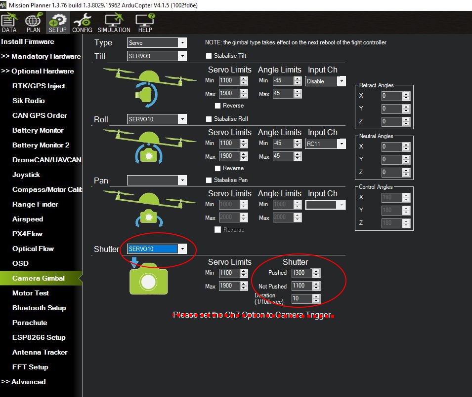
With high PWM it shoots picture, with low PWM it starts or stops filming, and with neutral PWM it waits orders, as simple as that, and you don't even have to bother with coding specificalities whether it's nikon, canon or sony, just plug it to a pixhawk channel, configure in mission planner that channel as shutter, and that's it!

Heres the classic camera shutter configuration from the documentation of APM at http://ardupilot.org/copter/docs/common-camera-shutter-with-servo.html:
missionplannercameragimbalscreen.jpg

Don't forget to have your camera activated infrared remote control. With Sony it works this way and with Nikon and Canon it can't be much harder than this too (I guess!):
3689688560?profile=original

To know that it's working correctly go to the Flight Data tab in Mission planner, right click on the map and chose Trigger Camera NOW. If the camera shoots a picture (make sure the LED points the camera's IR sensor at at least 1 or 2 meters away, but i prefer to just tape it next to the IR sensor), then it means the remote IR LED shutter is well configured and ready for work. If it starts a film, then just reverse the channel, and it'll start taking pictures.
From this point when you make a mapping mission your camera will shoot only when it's needed. No more hyper redundant picture shot by interval of time, or complicated hacking to your camera. Just the right pictures at the right time, no more no less.

3689688491?profile=original
By now all you need to do is prepare the Mission Planner to know your camera parameters and how to trigger the shutter only in the exact moment and here's the video explaining it:

https://www.youtube.com/watch?v=pQE4XWLqdmc


In the Trigger Method tab chose the CAM_TRIGG_DIST so the APM or Pixhawk gives the order to your camera to shoot the picture from the correct distance from the previous picture (it's the most efficient method).

If your camera isn't listed at Mission Planner camera's list, fear not! Create your own Camera Profile, after all it's just an xml file underneeth it. You just need to know the basic camera specifications. I found mine here:

http://www.imaging-resource.com/PRODS/sony-a6000/sony-a6000A.HTM

but it's always better to cross check with other sources (yep the manufacturer too :P) to make sure it's right. In this case it's right! :)

In my case (Sony A6000) the settings are as follows:
3689688389?profile=originalSave it, give the name of your camera, and it'll join the "authorized" mission planner's camera list giving you every single detail of your mapping flight mission. Sweet!

By now you are 100% ready to make mapping flight missions with full control of your plane and your sweet and trusty camera, and it costed by now only about 2 grams of payload with your LED camera shutter and 10 eurobucks plus shipping to your wallet.

By now you must be thinking YAY! Love this, can't wait to start mapping missions like a pro! And I then I tell you! "STOP!", and you ask "Why stop? What's wrong?", and I tell you "But there's even more sweet news to you!", and you ask "But what can be better than all this info you just gathered in one post?" and I tell you "I still have to tell you how to have your missions limited by you plane/copter's authonomy and not by the camera's battery weak authonomy of about 400 pictures!"

And now i'll proceed by telling you how to have the camera's autonomy to be able to make thousands and thousands of pictures tirelessly for about 12 eurobucks plus shipping.

First, buy a DC coupler compatible with Sony's battery NP-FW50.

71h8wkofnxL._SL1500_.jpg?width=600

I've bought mine at Amazon and weights about 30 grams:

http://www.amazon.de/dp/B00MHV677K/ref=pe_386171_38075861_TE_item

If you have other cameras just google eg Nikon or Canon DC Coupler and buy it from the best price.

To know more about the principles in using a dc couplers also known as "dummy batteries" with cameras watch this. It's easier then you imagine.

https://www.youtube.com/watch?v=qGZMfAHQBEo

In our case you'll power it to a ubec with around with steady 7.2V. Use a female connector in the ubec side, so you wont need to cut and adapt the dc couple plug. Don't forget to put a common LiPo battery or whatever capable of powering the camera for the whole flight. After all that's the point we want!

Additionally, if you want to FPV vertical videos (boring if it's the only camera) or want to pay attention to hundreds or thousands of pictures to see which ones get blured (gosh, what nonsense!) instead of paying attention to flying, just buy this Micro HDMI to AV converter for 21 USbucks plus shipping at Hobbyking:
http://www.hobbyking.com/hobbyking/store/__66466__Micro_HDMI_to_A_V...

66466.jpg?width=600

As usual if your camera isn't compatible with this, find one that is.

If you want to enjoy real FPVing with a frontal camera while piloting and then ocasionally check the mapping camera working right, you just need to buy a multiple camera switch controlable with a free channel in your radio, then buy this for 19 eurobucks plus shipping and weights about 2 or 3 grams.

https://rc-innovations.es/First-person-view-uav-multicopter-plane/F...

3689688604?profile=original

And that's it!


The Advantages of using these parts to your mapping missions with APM and Pixhawk are as follows.
- Dirty Cheap! Summing all parts (excluding the camera) used in this post it all costs around 60 euros;
- All components are very reliable and are non-vital for plane in case of failure;
- Light weight;

- The LED shutter uses IR light and not wifi spectrum frequencies which are susceptible of interfering with other RF transmitters/receivers in your plane/copter;

- You don't create metal fatigue with USB connectors, extending your camera's life expectancy.

- Tremendously increases the flight times of your mapping missions, increasing the covered areas per flight and thus being much more productive;

- It's that easy to assemble and understand even to noobs or people who just want to do more mapping and mess around less with electronics;
- You can georeference your photographs by using the mission planner tool as refered in this documentation with the much much much higher precision of the moment and position (and not estimated with the offsets method) where your camera was at the time of each picture was made;

- It takes only a couple of minutes to have your picture files geotagged;

- You don't have to mess around at all with your camera and thus voiding your manufacturers warranty. My camera survived warranty time and the extended warranty that I paid for (another waste of money) and it still works as good as new. (Thank you Sony for your outstanding products!);

- You can quickly shuffle your camera to work mode and tourist mode without nobody noticing they are in fact the same camera;

The Disadvantages are:
- If you want to buy a ready made system in one piece from one supplier instead of buing parts from several originsperhaps to save on shipping;
- There's no customer support and you're on your own if you chose this option, and that's a shame!

- Name yourself a reason.


One last tip:
If you want to avoid blurried images and happen to have a good camera such as the ones refered here, use a very large memory card, set your camera to produce RAW+JPG images files simultaneously, you'll thank later, use manual mode and get used to change the shutter speed, apperture and iso values to reduce bluried, too dark or too light pictures, etc. With experience you'll find that sweet spot with those 3 variables to be used ideally in any weather conditions'. Don't use auto mode, not even when you use the camera in tourist mode because it's lame and unprofessional. ;)
Read more about it here: https://photographylife.com/iso-shutter-speed-and-aperture-for-begi...

In the next days I'll reveal in detail the hardware system, the workflow and the coding involved on how to do in real time extraction of pictures files from a Sony Alpha cameras, inject its timing and positional data from APM/Pixhawk, upload the already georeferenced files to the cloud (Dropbox, Google Drive, Meocloud or whatever that pleases you better), having those images prepared for data crunching in the office as they keep arriving, having the quality control of the (too blurred, etc) images checked in the office, preparing in the office a new flight mission to redo the pictures that failed the quality control with the same orientation and position (as possible) as the original ones, inject the new mission plan to the flight controller and proceed with the new mission, all that before the plane lands from the first mapping mission (that benefits already from the goodies that I explained above).
For that, an interested person will only need to buy a raspberry pi 2 or 3, a broadband internet dongle, a wifi dongle and a few jumper conectors, an internet subscription, not to mention having one pilot in the field and at least another in the office to get the data and a good plane.
Not considering the salaries of the pilot and the office dude, the plane, the camera, the internet subscription, a good local network service and the broadband dongle (prices vary too much from country to country to consider it), I believe that the hardware needed to implement this will cost around 60 to 70 euros. The sourcecode to make it possible will be free from the start.
So if anybody is interested in knowing how to do this too, stay tuned to diydrones in the next days.

With best regards,
Roger Monongo

Read more…

rEHF_B2Ymf-5QSkO9-gssY61zro-6ogtyxl1mltTuvZmkjl0AV7l6lDKdzRH0bUqQDe7s6T2zUsH4y5szFo8Dam77TjKOzp-QqWrdMHIj6a1-Zcs_P67_eKKOh7UYIGGKjWCbWXwTjzgYVzn-uFgs3fPUiBZoWvgG9i2O81X0K6Uwk1qLwfNraoCfk6FfhUg9v0x3gRqAlsV-JCBZZqhlIkU7_cnndIMWlt9KPmPqC8NkCsK8ksSDhGLhc4SS1uP_8ROOa5_l-v_khk2wlLSJZUgXw6oAFWcga0oiwON0M0g_dbBrnWN6gQ3jC5II94f_mzZrY7O9DFgMGlzDM-o35eRZg-f-EpeB8Vgceur_bXvJpsNufFLFUPe9-aDi-7yeH7TvJ1V_sPyuXkq24vKNjSDyoQN4n0piwc20AtZTbJRYAxeeplnQ0Bg7R_NCrZUiAw3pH8wLEG9bX7G2xEb55Dj1DJFCqZLMyz0y5aFEgU0MfUZwLFJgiiqIsBvF0kAH_CSBC-OAgmjbVivLsq-2W1DSZLuodWGVNhQ3WVLV6RIPYF1eMeK4sxFFkYniSfcJj4=w800-h514-no?width=500

I just joined this forum with new id to share some info about this new drone project I started. 

This drone named Mantis280 is a 280 size quadcopter with fold-able arm and modular battery.

Modular battery is specially designed to slide into the body by un-folding the arm and fitted to the main connector thus secure both the battery and rear arms.

4dHkvIFnnW2orx37QcJ-ufOminw_3I09sujx3MoM1mBQn57XsdCTz7lXJFVyGkC850yCGL4CvYr6ZveuNXIp5ypzLeMvrq7uhhXJuzhkhv88kGCC46Ryql1d_76u7682J_STDq6FgDIgoQH372BLEgf52Gb0XpT2z2nAMzRUQX1ZuEJBq3KzMjfnJdHqUwmCjreAakfP-Gn83HGrMlxTbjGGFE-sweQwRk6WdmiWu5PEjYOVMvEbSQfusO4X_RpnOSFpbVOWX8PFNkzLLYj3AYH5xJs6DxWJcxASc_iDWCgQekjUf2mWp9doWmN8_NXDtt_kxVbNVuE_fRf53ieII5iXFO-KQZ_OqSRJ3JF2t78StkGu0Pp6qnEzofa5EpXCxNjrhJm3vdhkSodUjRC6S6IqAgqK9a5EkW18__oKB7xHPG0KBnpBrUyWAXfh2Q8-6rpVRToZJzch-3_6duCP6xkYqrwXGSLsQZT8sTMdf04MpT-TkTlwVKtTc4PA4PsGrlRHjz5Ypact7ReHRL38iJRSIZyy2x0q7u0Fv01F6voIPI4kIkmpnKZrhuCEBifWuZM=w779-h519-no?width=550

This battery module will be manufactured by China based company and development is in progress.

Below video will help understand how this work.

This drone is quite small but have enough room to accommodate different FCs including huge Pixhawk.

ib4dYRaSvRAypokbDj9frP5wsWKSIogCR4U82GIGmQe2L3w5-_vp2_J_aaUlRL4ARa69mLoZywltnnkkrX-ZUPTV8RjjtfkYYd1rtFQ2G6yFZkf2FM2l3lpZ7kF5558HUjLyODsUzyV6sWjwoJ-0q6AeT3OsMiLHYB5wbEnFsV8mbUMFbpsiZKE_OBiTkJJGLQp5pe78qaN8WGiMzLQriFTUv41zr0j3aB-aV-9CY6gtoW7MaXtfYf-s6bDePlIH1hTRvgsI_0L7C-z99zUSyZyeGsW_McGZ6nRXRDXRpOGaNhQD2euvXfKVigRDi7bjTfPM8JP6IPkW3qGpCrW6oZ1BlkKgnEIpl1jgDxX8WVRR0IggGja5D7xzrRpHJsEL0D9_dFq7pVaKi8YJVd_AEZrocuTevhFXFyupM9eqXTvkmoqwDcSYmQNSE5F6DBObBph1BVcpphPI1IuqZGvCv9LjanFTU7KxS76nUQgoOpGwNjdp6S0R0AKVpuApJPvQtdebtumbX7ITVqP2KOVrDzfFUnwkDoKCFtZxGRL_Eax5QUZa97zz-n2VEOQb4jLox6A=w779-h519-no?width=550

Below picture shows all the components needed to build this drone and they all can be 3d printed!

I used one of high-end 3d printers for this but I am sure any low-cost 3d printer can print this.

p0I7z05REA7m_zX68PgAiPSRG74mg6M7OmQmCyR9gAqH77spakqQpw4ENlGyRxuTeaBHzVK-4x5uP9Cdh80x89ZE1saA2EHZpci1ZnXC4ShRCWC3y1MWk2ifJV8SvKw1odrqTggfwyYpTGy6fmOyO0_mDs2KL6jPsjaYO2C5tBHGRXLD2NcMCaz_nSHFmw35NjQjZtDYy4mat64KqmKhbyaD13w68LnrixZU51yUgkQwRek_x9IzQU1n3ssm96RK4IYv5AVkHPe_L3lp4qc2uXz7nwHdcwDlMSSUNcRIphzaf5x2HEuNoUsgpUoLCSqLzL6maYkbArG4BtgP5QISZu5GwUZC13MNuyOsjce0s5eYwdw7j_qHf_mVdrcG3Mwqn2DJSfL34XJ1saHmB_NnEgE649k4Ay3WUpyNqMv5Vtaj_lFxnVmp3hq4eXmsnrzDdm5TZBq2jsHt0LBY5wcX09NwuSyy07EscCmWN-PRGo7sX21PggdeEkTQxsMN9YdNdbBF0BmwVxcgof0g1yo6pLJbrLjZswM56TQ88-cqy8hhnGPOmKrH2YauCcaKNhHcyQI=w981-h519-no?width=550

Although it is not fully tested yet, I am sure this platform will be very helpful for some researchers and even some professionals with right controllers. 

I am planning to raise funds to make full product by crowdfunding such as Kickstarter. 

Exact launch date is not fixed yet though, if you like this project please follow us and help raise funds!

Thanks all,


Read more…

Festo FreeMotionHandling

They have done it again, Festo thinking out of the box.

Both gripping and flying have long been a topic for the Bionic Learning Network. In the FreeMotionHandling, Festo has for the first time combined both areas. The indoor flying object can manoeuvre autonomously in any direction, independently picking up and dropping off items where they are required.

Autonomous flying gripping sphere

Both gripping and flying have long been a topic for the Bionic Learning Network. In the FreeMotionHandling, Festo has for the first time combined both areas. The indoor flying object can manoeuvre autonomously in any direction, independently picking up and dropping off items where they are required.

Flying assistance system for handling in mid-air

The handling system consists of an ultra-light carbon ring with eight adaptive propellers. In the middle of the ring sits a rotatable helium ball with an integrated gripping element. As a result, both man and machine can interact with each other easily and safely, opening up entirely new possibilities for the workplace of the future. In this future, people could be supported by the spheres, using them as a flying assistance system – for example, when working at giddying heights or in hard-to-access areas

Exact position sensing and precise object detection

No pilot is required to control the flying object. The sphere is coordinated externally by an indoor GPS, which has already been tried and tested on the eMotionSpheres and eMotionButterflies. In addition, the handling unit features two on-board cameras with which it monitors its surroundings, reacting to its environment even during the gripping process. Upon nearing the object to be gripped, the system takes over route planning, using the twin cameras for coordination.

 https://www.festo.com/group/en/cms/11957.htm

taken from

http://www.suasnews.com/2016/04/festo-freemotionhandling/

Read more…
3D Robotics

Suffice to say it doesn't end well, for drone or engine. Why did the researchers use an 8-lb drone, when the typical drone weighs less than half that?  The researcher responded:

"This is the drone size that one European country has sanctioned for their postal services to deliver packages to high altitudes. The work is not based on any organization’s request. We are able to model a variety of different drone sizes and models. We chose this model as a demonstrator, because it was one of the larger size commercial drones available that is capable of carrying large weights and reaching higher ceilings."

Excerpt from the full story:

...The smart folks at Virginia Tech’s CRASH (Crashworthiness for Aerospace Structures and Hybrids) lab have been working hard to answer these questions. Founded and directed by Professor Javid Bayandor, the team at the CRASH lab’s latest endeavor has been to build simulation models for turbofan engines, drone components, and basically smash them into each other to see what happens. From a Virginia Tech press release,

An 8-pound quadcopter drone can rip apart the fan blades of a 9-foot diameter turbofan engine during take-off in less than 1/200th of a second. The speed of drone debris thrashing about inside the engine could reach speeds 715 miles per hour. Broken blades also would create more fragments as the fan crumbles and warps the engine block housing, contributing to catastrophic engine failure.

So there is little doubt that a drone of this large size would cause catastrophic engine failure. This sort of damage would be consistent with the type of damage that occurs regularly with a ingestion of a large bird. However thanks to FAA standards for aircraft engine design, the failure and detachment of a rotor blade is anticipated, and must be contained within the engine. Failure to contain a blade could obviously lead to other damages, from structural parts, to fuel tanks, electrical controls, or even death or injury. It has happened on older designs, such as Delta 1288, a MD-88 that failed and engine parts entered the passenger compartment, killing 2 (this was a 1963 designed engine).

...

An 8 lb drone is not the type that one would get for Christmas and be used by a younger, less responsible person however. Without crunching the numbers, I suspect a smaller DJI Phantom sized drone at 13″ and 2.6 lbs would be more likely to be the first to actually get ingested into an engine. The Phantom seems to be the ‘go to’ drone for people first entering the hobby, and is most likely to be operated by those without any real knowledge of airspace or air safety.

Our plans are to study a full array of drone sizes, with different materials, weights, and  configurations.

adds Professor Bayandor. Materials is also one of the topics that the CRASH team is studying. Currently, “The drone is composite, but the core is made of denser metal alloys.”. As we know, drones built from carbon fiber and alloys are not the only type we will see. Google has previously demonstrated a delivery drone in a wing form, made primarily from foam.

161434603_01_758991b

However, he adds, “In this early stage of the study, it seems that battery packs and on-board cameras can cause most damage. ”

I posed the question of what materials are likely to cause the most damage to the turbofan engine? Carbon Fiber tubes and plates, aluminum parts such as motor shells, circuit boards, LiPo battery packs? Professor Bayandor reports, “At this point, we are still formalizing our material modeling matrix, but the materials mentioned are among the general candidates considered.”

Read more…

deep-bluerov-hi-1

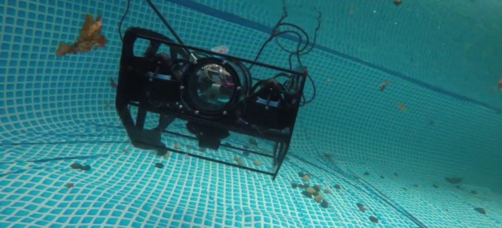
Hello everyone! I want to share something that we’ve been working on for quite a while at Blue Robotics. If you follow the ArduBoat group or TCIII's ROV build thread, you may have already seen a bit about it.

This new project is called ArduSub.

ArduSub, we hope, will become the open-source future of subsea vehicles. It encompasses the software and hardware that makes up the brain of an ROV or AUV, providing everything needed to control the vehicle, communicate with the surface, and perform sophisticated subsea missions.

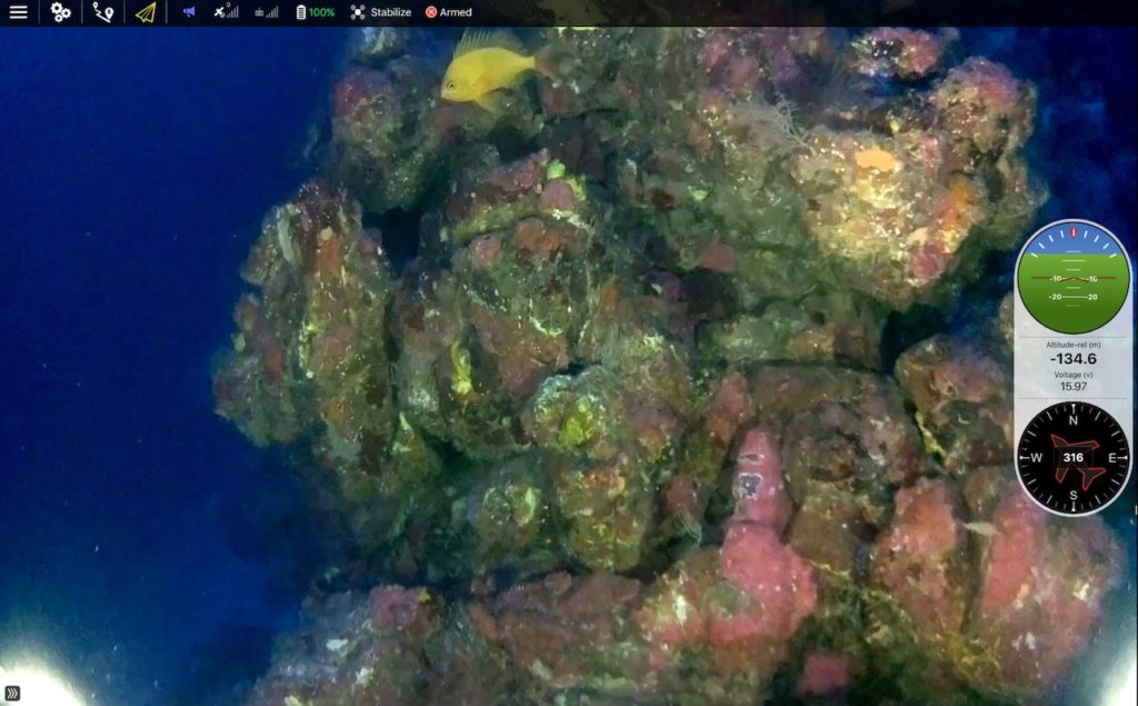
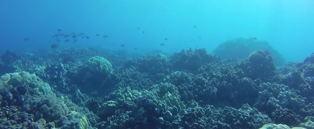
reef-bluerov-hi-1-1-1024x422.jpg?width=600Reef image captured by an ArduSub-powered ROV.

ArduSub is based on the open-source ArduPilot project (ArduCopter, specifically) and takes it to a new frontier with subsea capabilities targeted towards ROVs and AUVs. ArduSub is already compatible with most DroneCode autopilots including the PixHawk.

bluerov-dev-1

Stability PID tuning during development of ArduSub.

What does that mean for future ArduSub users? It means that this project isn’t started from scratch – it’s born from years of previous development work, hundreds of contributors, thousands of hours of testing, and several generations of hardware. That provides us with a rapid path to maturity and already-built-in capabilities and features that surpass those of many commercial ROVs.

It also means options. ArduSub is compatible with ten or more different hardware autopilot options, multiple topside user interfaces on every operating system, a wide variety of sensors and actuators, and a host of tools such as DroneKit, mavros, and more.

All of this is thanks to the open-source community that has been working on ArduPilot for many years. Blue Robotics is committed to supporting the continued work of that community and to contribute back to it. We have proudly joined the DroneCode Foundation, which manages the ArduPilot codebase, and hope to support this great organization for many years.

logo.png?width=300

Where are we at right now? ArduSub is currently capable of controlling several different ROV frame styles and has support for gamepad/joystick use through QGroundControl, depth/heading hold, lights, and video streaming to QGC. We've done lots of testing including ROV dives down to 135 meter depth.

What’s next? With the help of several contributors and a number of beta testers, we are making steady progress towards the first official release of ArduSub. We're working on lots of improvements to make it easier to set up and easier to use. ArduSub is still under heavy development and there are new changes happening often. Please follow along and let us know if you’d like to join in.

More info:

Also:

Read more…