All Posts (11086)

Sort by

IMG_9708.JPG.620x349_q85_crop-smart.jpg?width=400

Anyone else building an autonomous rover perhaps for Robomagellan or Sparkfun AVC? Do you have a multiplexer on your one-off, scratch built autopilot solution? If not, I built something just for us. :)

Picture your robot driving right at a curb or a wall. No problem, just take over with an RC multiplexer installed. It's saved my bacon plenty over the last couple years. APM users no doubt have many similar experiences with their built-in mux.

They're now available for pre-order for $12. I'll be ordering R0.2 boards soon.

Now, you may recall the AVC prohibited RC transmitters. Well, the mux on Data Bus been invaluable during testing, primarily. I'll be using one of these boards on Data Bus in prep for The 2014 AVC.

  • 3 R/C channel multiplexer, designed especially for rovers
  • Reliable, standalone design; keeps running even if your autopilot MCU doesn't
  • Color-coded pin headers for fast, correct installation
  • Fully assembled
  • Easily select between autonomous and manual control
  • Two inputs: R/C and MCU, clearly labeled on the board
  • Two LEDs indicate autonomous or manual control.
  • Onboard regulator
  • Compatible with common 5V, 5.5V or 6V BEC
  • Power rail transmits power from BEC to Receiver, Servo, MCU
  • Firmware pre-loaded or program the ATtiny13 yourself
  • Open source (hardware and firmware)

IMG_9712.JPG.620x349_q85_crop-smart.jpg?width=400

RoverMux_DataBus1.png.620x349_q85_crop-smart.png?width=400

Read more…
3D Robotics

3689544837?profile=originalDon't ask me how these might work, but it's fun to think about at least. From Mashable:

If you've ever wished your house would automatically clean itself, so you could get a little free time — you're not alone. An industrial-design student in Colombia has conceptualized an automated cleaning system in which flying robots would do all the dirty work.

Designer Adrian Perez Zapata came up with "Mab," which harnesses hundreds of mini-robots equipped with a cleaning solution to tidy up homes. Zapata, 23, is among 20 semifinalists in the 2013 Electrolux Design Lab competition. This year's theme is "inspired urban living," so undergraduate- and graduate-student participants can submit design solutions in the categories of social cooking, natural air and effortless cleaning.

The Mab concept requires users to load water and a chemical substance into the system's spherical core. The cleaning liquid is then distributed to 908 mini-robots, which are each equipped with propellers for flying. After that, the mini-robots are dispatched, scanning the home and cleaning surfaces with droplets of fluid. Dirt is captured and carried back to the core. The little bots would be powered by the solar energy collected via their wings.

Electrolux Design's Thomas Johansson called Mab a "bold solution, which mimics the collection of honey bees."

Read more…

3689544745?profile=original

Yes! Another APM 2.5 powered quadrotor took to the air in South Carolina. All that energy, time, effort and planning paid off this evening with the maiden flight of my entry into the DIY Drones sponsored Instructables Drone Contest. The build is HERE. 

The idea behind this tube and plate project was to reduce the amount of hardware and aluminum used in an effort to reduce weight and cost. The ultimate goal would be a lower cost build that high school kids could afford. Of course a DJI clone air frame is cheap, but as I mention in the Instructable..

Creating/making uses cognitive processes and develops/enhances motor skills.

I chose not to use GPS on this build, again as a cost reduction effort and motivation for a school build. It would be a great project for a STEM program. A different motor mounting method was used for this build...

3689544812?profile=original

Rather than fighting to access motor screws through a couple of holes in the bottom of the arm, the arm area below was machined away to make it easy to install the screws. I used the same 'angle mount' idea from my first quad but as these motors were larger, I had to machine some relief into the side walls to allow the screw heads to clear. Sure, I could have reduced the heads of the screws or perhaps found some screws with smaller heads but, this fix provided the simple fix. (Psst... hey 3DR.. if you 'borrow' this idea for AC-4, I will be flattered.)

I am working on my new CNC machine so it was not ready to make the holes for me. I devised a jig, used on the previous quad for marking the holes on the arms.

3689544777?profile=original

The width of the jig is the width of the arm material (0.75 in square). The jig straddles the arm and then the holes are marked.

3689544865?profile=original

So, how did it fly? Not bad considering I didn't check the battery level prior to the flight. The flying weight of the WBQ was just under the weight of my first quad. The difference was this quad uses the heavier motors (gold vs purple). I was surprised by this when I pulled the motors out of their bags. The motors were 3DR units bought off a DIYD member who had posted them in the Buy/Sale/Trade forum.

Three throttle up/lift off runs were made: Throttle Out is graphed below.

3689544787?profile=originalThe first hump was to ensure that the controls were right way around. Some tendency to roll right was noticed but with almost no tuning of the PID variables, I was not surprised. The second cycle, obviously longer was more relaxed and I was able to almost take my thumb off the directional stick. By the third cycle it was becoming fun. As the battery faded, you can see that I commanded more throttle to maintain hover..until the APM finally decided the battery was done. Stabilized mode was used for this evening's flights.

Pre-flight problems? Yep -- mostly just two:

  • The prop collets were nearly uncooperative. I found that mixing up the spinner nuts was a bad idea. The thread quality varied and seems to be unit specific. Take that as a tip and keep them together when pulled from their bags. Who knows how many different shops a pile of those things were made in?
  • ESC and radio calibrations had to be performed again. The new instruction for Arducopter, specifically the ESC calibration video, is great. A+ to the documentation teams.

If the two problems had not surfaced, I had hoped to get my wife to take some photos. Alas the tests were done near the cover of dark and in partial carport lighting shining onto my driveway. I do want some photos of it in the air to update the Instructable build and to show the skeptics that it really does fly.

My plans for this quad are mainly to educate and demonstrate that the material costs for an quadrotor can be held low but still not utilize what I call 'Minimalist Adaptations'. There still exists a need for young people to take raw material, use their minds, and create something interesting, useful, and fun. The greatest benefit is they might learn something practical in the process.

Build on!

-=Doug

Read more…

Externally accessible pins APM1 and APM2

3689544697?profile=originalIf somebody else had ideas about using old APM1's and soon to become old APM2's for some different purpose than autopiloting - probably you will want to connect some hardware, right?

I have gone through what I could find of documentation, and measured what was not documented.

Here is a brief overview of the connections on APM1 and APM2 that are available, once external servo wires and external (voltage, current, airspeed etc.) sensors are removed. Especially the APM1 "oilpan" shield has many routed but unused pin connections.

Not included are: UARTs, SPI and I2C, as they are pretty obvious.

External ports APM1:

Where nothing else is mentioned, connections are to the ATMEGA2560.

APM1 PWM inputs:

PWM inputs IN0..IN8: PD0..PD7 on the PPM encoder ATMEGA328p. They are hardly useful for general purpose IO, as there is only the single PPM wire to communicate to the ATMEGA2560 via.

PL0 (ICP4) is the ATMEGA1280/2560 PPM input pin.

APM1 PWM outputs:

PWM output OUT1: PL4 (OC5B) via 220R resistor
PWM output OUT2: PL5 (OC5C) via 220R resistor
PWM output OUT3: PB6 (OC1B) via 220R resistor
PWM output OUT4: PB7 (OC1C) via 220R resistor
PWM output OUT5: PH5 (OC4C) via 220R resistor
PWM output OUT6: PH4 (OC4B) via 220R resistor
PWM output OUT7: PE5 (OC3C) via 220R resistor
PWM output OUT8: PE4 (OC3B) via 220R resistor
Unknown pin on oilpan: PB5 (OC1A)
Unknown pin on oilpan: PE3 (OC3A)

APM1 Analog:

A0: PF0 via 10k resistor

A1: PF1 via 10k resistor
A2: PF2 via 10k resistor
A3: PF3 via 10k resistor
A4: PF4
A5: PF5
A6 ("expansion port"): PF6
A7:("expansion port"): PF7

APM1 Other:

PD0, PD1 are I2C. PD2, PD3 are UART1. PE0, PE1 are UART0.
PG0 is SW1 the unused button (AFAIK completely ignored in Ardupilot soft).
PG1 is the "slider switch" (AFAIK completely ignored in Ardupilot soft).
PORTC is routed to Oilpan (JP14). PC0, PC1, PC2 are the three LEDs.

Which port is driving / did drive the relay? It is Arduino Pin47, PL2?

PE6, PE7 and PL6, PL7 are the Oilpan DIP switches (AFAIK completely ignored in Ardupilot soft).

External ports APM2:
Where nothing else is mentioned, connections are to the ATMEGA2560.

APM2 PWM inputs:

PWM inputs IN0..IN8: PB0..PB7 on the PPM encoder ATMEGA8U2. There is a serial connection between ATMEGA8U2 and ATMEGA2560, so a custom firmware on 8U2 could forward (slow) data to/from 2560 from/to the port.

PL1 (ICP5) is the ATMEGA2560 PPM input pin.

APM2 PWM outputs:
PWM output OUT1: PB6 (OC1B) via 220R resistor
PWM output OUT2: PB5 (OC1A) via 220R resistor
PWM output OUT3: PH5 (OC4C) via 220R resistor
PWM output OUT4: PH4 (OC4B) via 220R resistor
PWM output OUT5: PH3 (OC4A) via 220R resistor
PWM output OUT6: PE5 (OC3C) via 220R resistor
PWM output OUT7: PE4 (OC3B) via 220R resistor
PWM output OUT8: PE3 (OC3A) via 220Rk resistor

PB7 = OC1C (NOTE Ch.9 out is not supported in firmware!!!)

APM2 Analog:
A0-A7: PF0..PF7 = ADC0..ADC7 (used for analog signals)
A8: PK0 = ADC8
A9: PK1 = ADC9 or PB7 (default) jumper selectable. PB7 via 1k resistor.
A10: PK2 = ADC10 or PL4 (default) jumper selectable. PL4 via 1k resistor. PL4 = OC5B
A11: PK3 = ADC11 or PL5 (default) jumper selectable. PL5 via 1k resistor. PL5 = OC5C

Read more…

TBS Disco - first flight report

Another TBS disco build...

3689544652?profile=original

Summary:
Flies surprisingly well! It still seems a bit "pendulum-y" in pitch, but on the whole, it flies very straight and true. Needs a fair bit of power to get in the air though. But yet another unrequested land event for reasons unknown. I wasn't stressing it at the time. I have one of these nearly once a pack.

Stats:

Take off throttle: Around 65%

Flight time: Around 14 minutes, pushing it around.

Compassmot: 0%. Yup.

Vibes: Good (and this while pushing it around a bit). Full sticks will take it to the recommended +/-5 limit though.

3689544620?profile=original

COG: With a 5000mAh 3S, I'm on the furthest internal rungs on the frame. This in turn pushes the APM to overhang the Core a fair bit. This meant putting in 4x 6mm risers, and balancing the APM on these, using double moongel corners. A whole section of moongel was placed over the core, which helped keep the APM level.

PID's:

- V config selected

- Roll and pitch linked

P: 0.145

I:0

D: 0.008

- Yaw - P bumped to: 0.225

All other dynamics settings at factory default (I've made changes to RTL and failsafes though).

Specs:

- TBS Disco version 1.3 with "Core" (inc the worst screws ever to come out of china btw)

- APM 2.5+ with double moongel corners

- APM power module

- External "2.6" GPS

- DJI riser (cut to 5cm...c'mon 3DR, some longer wires for the new unit please!)

- Rctimer Simonk 30A OPTO escs with one twist in power cable and shortened to 3cm before soldering

- Spektrum AR8000 (telemetry disconnected this time)

- T-Motor 2216-11's

- Graupeur e-power 1050 props (will upgrade to CF once flight tuning is done)

- Immersionrc 5.8 25mwW + bluebeam (yes, that's *way* underpowered!)

- 433mhz 3DR telemetry

- Nano-tech 5000mAh 3S.

First flight post-PID calibration. Some high frequency vibes at the edge of frame; not sure what's causing those yet. PID's too high? Flew FPV via gopro and crappy whip aerial while waiting for bluebeam and CCD; was ok actually - surprisingly good range!

Read more…

Isolated frame Octa will soon be ready.

3689544515?profile=original

Following on from the very successful H quad with vibration isolated arms I decided to build something that would lift a DSLR or larger.

Is seems a hex has marginal chances of surviving a single drive failure so I opted for an octa. The H8 was quite an attractive layout but the loss of efficiency and lift was too much so I decided to build a flat 8. It also had to fold down to less than 35cm wide if possible. I wanted to keep a vibration isolation system but the method used on the quad was not suitable. I opted for a separate frame which carries all the heavy and vibration sensitive items like controller and camera, all suspended on silicone ‘O’ rings. Rings can be added or tightened to ‘tune’ the system. Provision is in place for z axis O rings if required but with 6 rings it each corner it is already very stiff in all axis.

I was part way through the build and struggling to get the folding arm system working nicely when my son ordered a 3d printer. I was very sceptical despite their popularity on this site.

After the first few printed items came off I wondered how I ever managed without one and my poor son didn’t get a look in – sorry Leo.

Once all the plastic parts are printed it doesn’t take very long to cut the carbon to length and assemble it.

eCalc suggests it will have a max TOW of 8kg (inc 3.3 kg payload) and hover time of 11 mins at that weight. More realistically, with a DSLR and 4 x 5AH 4s is should be about 5.3kg and 22 mins. (This is using MT4008-12 with 14x4.7 props)

I am considering a production run of these frames once this one is proven.


3689544450?profile=original3689544521?profile=original3689544554?profile=original


Read more…
MR60

As the third and last episode of these summer flights in France, I played around with a great little quad, from Walkera, the Ladybird. It looks like a toy really but it is a full fledged quadcopter with amazing compacity:

-the controller board integrates all of the electronics  : ESCs, Radio receiver, Accelerometers (6-axis), etc

-in a tiny form factor: the board's size is a little bit more than 1,5 inch WxL:


3689544482?profile=originalThis is truly amazing. You can program it in the equivalent of our APM "Stabilize" mode or "Acro" mode.

In Acro mode you can do flips and rolls! (i broke quite a lot of shells => foresee replacement parts).


The idea of completing your quadcopter/hexa/octo existing arsenbal with such a small addition is obvious for me: you get the best training platform, ultra resistant to shocks, and much better than a simulator. It really behaves like a real quad int he flying sensations (very sporty one). With this I learned to fly my more expensive and serious drones in different orientations, something I would never had tried with "expensive" material. (and I do not like the artificial simulators to train). Further it is half the price of a software simulator !!!


It flies and sounds like a drone (you'd think a big insect is flying near you) : when we will have killed all of the bees, we should have some robotics substitutes... The attached video shows some fun with it.


Read more…

Modding a Wikipad for use as a ground station

3689544430?profile=original

Hi all,

I got a Wikipad (an Android tablet that targets gamers) to experiment with as a ground station / second TX, mostly because it has dual joysticks. There is a lot of work to be done until it has RC-controller like capabilities. First step was a workaround for the design flaw that no USB data ports are exposed when you have the tablet snapped into the joysticks. I did the mod and then made this guide:

wikipadMod.pdf

Hope you guys find this useful! I will be working to add Wikipad support to Droidplanner and maybe Andropilot too.

Aaron

Read more…
3D Robotics

3689544395?profile=original

Great piece in the Guardian. Nice DIY Drones call-out, too. Sounds like they're using our stuff!

In Peru, home to the spectacular Inca city of Machu Picchu and thousands of ancient ruins, archaeologists are turning to drones to speed up sluggish survey work and protect sites from squatters, builders and miners.

Remote-controlled aircraft were developed for military purposes and the US is increasingly using them to attack alleged terrorists, but the technology's falling price means it is increasingly used for civilian and commercial projects around the world.

Small drones have been helping a growing number of researchers produce three-dimensional models of Peruvian sites instead of the usual flat maps – and in days and weeks instead of months and years.

Speed is important to archaeologists here. Peru's economy has grown at an average of 6.5% a year over the past decade, and development pressures have surpassed looting as the main threat to the country's cultural treasures, according to the government.

Researchers are still picking up the pieces after a pyramid near Lima, believed to have been built 5,000 years ago by a fire-revering coastal society, was razed in July by construction firms. The same month, residents of a town near the pre-Incan ruins of Yanamarca reported that miners digging for quartz were damaging the three-storey stone structures.

And squatters and farmers repeatedly try to seize land near important sites such as Chan Chan on the northern coast, thought to be the biggest adobe city in the world.

Archaeologists say drones can help set boundaries to protect sites, monitor threats and create a digital repository of ruins that can help build awareness and aid in the reconstruction of any damage.

"We see them as a vital tool for conservation," said Ana Maria Hoyle, an archaeologist with the culture ministry.

Hoyle said the government planned to buy several drones and the technology will help the ministry comply with a new business-friendly law that has tightened the deadline for determining whether land slated for development might contain cultural artefacts.

Commercial drones made by the Swiss company senseFly and the US firms Aurora Flight Sciences and Helicopter World have all flown over Peru.

Drones are already saving archaeologists time in mapping sites – a crucial but often slow first step before major excavation work can begin. Mapping typically involves tedious ground-level observations with theodolites or pen and paper.

"With this technology, I was able to do in a few days what had taken me years to do," said Luis Jaime Castillo, a Peruvian archaeologist with Lima's Catholic University and an incoming deputy culture minister who plans to use drones to help safeguard Peru's archaeological heritage.

Castillo started using a drone two years ago to explore the San José de Moro site, an ancient burial ground encompassing 150 hectares (0.58 sq miles) in north-western Peru, where the discovery of several tombs of priestesses suggests that women ruled the coastal Moche civilisation.

"We have always wanted to have a bird's-eye view of where we are working," said Castillo.

In the past, researchers have rented small planes and strapped cameras to kites and helium-filled balloons, but those methods can be expensive and clumsy. Now they can build drones small enough to hold with two hands for as little as £650.

"It's like having a scalpel instead of a club. You can control it to a very fine degree," said Jeffrey Quilter, an archaeologist with Harvard University who has worked at San José de Moro and other sites in Peru. "You can go up three metres and photograph a room, 300 metres and photograph a site, or you can go up 3,000 metres and photograph the entire valley."

Drones have flown over at least six archaeological sites in Peru in the past year, including the colonial Andean town Machu Llacta 4,000 metres (13,123 feet) above sea level.

Peru is well known for the stunning ruins of the 15th-century Machu Picchu, probably a getaway for Incan royalty that the Spanish were unaware of during their conquest, and the Nazca Lines in southern Peru, which are best seen from above and were mysteriously etched into the desert more than 1,500 years ago.

But archaeologists are just as excited about other chapters of Peru's pre-Hispanic past, such as coastal societies that used irrigation in arid valleys, the Wari empire that conquered the Andes long before the Incas, and ancient farmers who appear to have been domesticating crops as early as 10,000 years ago.

With an archaeology budget of about £3m, the culture ministry often struggles to protect Peru's more than 13,000 sites. Only around 2,500 have been properly marked off, according to the ministry.

"And when a site is not properly demarcated, it is illegally occupied, destroyed, wiped from the map," said Blanca Alva, an official with the ministry charged with oversight.

Steve Wernke, an archaeologist with Vanderbilt University exploring the shift from Incan to Spanish rule in the Andes, started looking into drones more than two years ago.

He tried out a drone package from a US company that cost about $40,000 (£26,000). But after the small plane had problems flying in the thin air of the Andes, Wernke and his colleague, engineer Julie Adams, teamed up and built two drones for less than $2,000.

The drones continue to have altitude problems in the Andes, and Wernke and Adams now plan to make a drone blimp.

"There is an enormous democratisation of the technology happening now," Wernke said, adding that do-it-yourself websites such as DIYdrones.com have helped enthusiasts share information.

"The software that these things are run on is all open-source. None of it is locked behind company patents," he said.

There are some drawbacks to using drones in archaeology. Batteries are big and short-lived, it can take time to learn to work with the sophisticated software and most drones struggle to fly in higher altitudes.

In the US, broader use of drones has raised privacy and safety concerns that have delayed regulatory approval. Several states have drafted legislation to restrict their use, and one town has even considered offering rewards to anyone who shoots a drone down.

But in Peru, archaeologists say that it is only a matter of time before drones replace decades-old tools still used in their field, and that the technology can and should be used for less destructive uses.

"So much of the technology we use every day comes from warfare," said Hoyle. "It is natural this is happening."
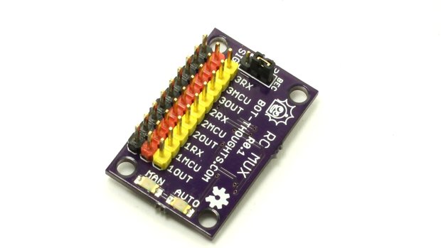
Photo credit: "Peruvian archaeologist Luis Jaime Castillo flies a drone over Cerro Chepén, one of thousands of ancient ruins across Peru. Photograph: Mariana Bazo/Reuters"

Read more…

Autonomous sail boat and electronic wind vane

I have started to build an APM controlled sail boat. 

3689544336?profile=original

The hull

The hull is based on a IOM boat called Goth (Free plans here). It is built with balsa strips and then glassed on both the inside and outside. Keel blade and rudder are made with balsa cores and a carbon fiber shell. The bulb is 3.5 kg lead. It is designed to weight 4.2 kg when finished. 

The wind vane

The wind vane is built around the magnetic rotation sensor chip as5045. With a magnet placed just above the sensor it can detect the absolute angle of the magnet. The magnet can be seen below the ball bearing in the image below. The sensor chip measures just 5x5 mm and is embedded in epoxy. The wind vane and the sensor is placed in the tube and voila. A wind direction sensor with almost no friction and a total weight of less than 10 g. Total length is 10 cm.

I still need to figure  out where to put the wind sensor. Since i have a rotating mast it is not a good idea to put it there unless i fit another rotation sensor on the mast. 

The wind vane is quite sensitive. It works at walking pace so hopefully it will work on the boat.

3689544248?profile=original

Mast

The mast and boom is made of a fiber glass fishing pole. the sail is made drawing film. It is made as an IOM sail and the sail area is similar to an IOM size two sail (main plus jib).

3689544361?profile=original

I have not decided how to control the sail. I can use a traditional sail servo or rotate the mast with an arrangement under deck. 

Control

The boat will be controlled using the APM hardware and sensor libraries. 

The plan is to take it step by step:

  1. Manual RC-control
  2. Manual RC-steering with automatic sail control
  3. Heading and/or Wind angle hold. 
  4. ...

All comments and ideas are welcome!

/Magnus

Read more…
3D Robotics

3689544287?profile=originalFrom The Verge (with suitable skepticism)

German non-profit group Definetz wants to make defibrillators readily available across its country so that any time someone has a heart attack, the life saving devices are within arms reach. And it's looking to drones to help it bring its vision to fruition. On Friday, the group announced the Defikopter, a concept device it designed with drone-maker Height Tech to fly defibrillators to emergency responders or the public by way of a GPS-enabled smartphone app.

Definetz says the Defikopter, which was developed over the last three months, can travel within a radius of 10 kilometers (about six miles), and fly at a speed of 70 kilometers per hour (about 43 miles per hour). While Definetz and Height Tech have announced their collaborative design, neither organization said if or when the Defikopter would be made available for sale, or when and if the corresponding smartphone app would be released to the public.

There are, of course, a few drawbacks to the drone concept. If built, the drone hardware would sell for about $26,000, according to the Mittelbayerische news site. Additionally, if the Defikopter and its app are made available, the Defikopter can only be hailed by someone who is with a heart attack victim and already has the app downloaded downloaded on their phone. The drone also can't run without supervision — the Die Glocke newspaper reports that German law requires that unmanned flying vehicles can only be flown if monitored by a human being. These limitations and restrictions could mean the Defikopter concept never makes it off the ground.

Read more…

DIY Camera Filter Swap on a Canon Powershot

SAMSUNG CSC

I wrote a few weeks ago about testing out a Schott BG3 filter on an SX260 for detecting vegetation stress remotely. That post and the results of this conversion are posted here. We’re now selling both those filters individually as well as pre-modified cameras at Event 38 for those interested in testing them out, but be aware before you grab one that the processes related to setting the right white balance, calibrating imagery to compare results from different pictures and even post-processing are not yet finished. We’ll be working on improving these but I wanted to make available what we have right away because there are some people interested in getting started right away. The process shown below will work just as well for any other filter you get anywhere else.

Before you start, it’s good to have a good selection of screw drivers, a brush, an air puffer, a marker and tweezers close by.

SAMSUNG CSC

To start, remove the back section of the camera by unscrewing 1 bottom, 2 right and 2 left side screws.

SAMSUNG CSC


SAMSUNG CSC

Once the back is loose, pull it off gently and remove the flex cable by sliding it upwards out of the socket.

SAMSUNG CSC

Next, remove the bracket holding the right side of the LCD in place by removing the single screw at the top.

SAMSUNG CSC

Now the LCD is loose. Slide it a bit to the right so it clears the lip on its left side and then pull it up on the left side. There is a flex cable in the upper right corner that can’t be pulled too hard or it will come out. Accessing it to replace it is very laborious so be careful not to put too much stress on that cable! I use masking tape to keep the LCD up and out of the way while working beneath it.

SAMSUNG CSC

We’ll be unscrewing the 3 screws on the back of the sensor in a moment but first we need to remove the glue holding the sensor plate down. The glue is pretty tough, so I use a really sharp exacto knife to scrape it away bit by bit. Quick, light cuts work better and are less likely to damage something else than pushing hard so be gentle. Use a brush or air puffer periodically to remove the debris.

SAMSUNG CSC

Once the glue is out of the way, mark each screw’s position using a marker before unscrewing them. Make sure to set the screws aside in a way that you know which position to return it to later.

SAMSUNG CSC

Take the screws out and gently remove the sensor plate. Clean the area again to remove any dirt/dust that has fallen in. The reddish piece of glass in the center is the IR-block filter that normally keeps out all infrared light. Remove the rubber placeholder holding the filter in place.

SAMSUNG CSC

Remove the filter glass carefully using tweezers and set it somewhere safe in case you need to put it back in later.

SAMSUNG CSC

Clean the entire area again.

SAMSUNG CSC

Now carefully drop in your filter glass.

SAMSUNG CSC


SAMSUNG CSC

Replace the rubber placeholder and then the sensor plate on top.

SAMSUNG CSC

Replace the screws in the right order and screw them in until the marks match up as closely as possible.

SAMSUNG CSC

Close the camera back up by replacing all the screws and brackets and don’t forget the flex cable on the back of the case. Finally you’ll want to check and make sure there’s no dust on the sensor or inside of the lens. Put the camera in Aperture priority mode and open up the aperture as wide as possible. Zoom the lens in all the way and focus the camera on something far away by half-pressing the shutter button. Now aim the camera at a clear sky or a white piece of paper and make sure it fills the entire screen. Take that picture and then look at it to make sure there are no black spots, below is the image as it came out of the camera used in this tutorial.

IMG_0755

If your image came out clean too then you’re all set! If you’re using a Schott BG3 filter, a quick and easy way to start processing images for vegetation stress is to set the camera’s white balance to the cloudy preset. This will allow you to process a vegetation index that represents vegetative cover and growth, although the results don’t yet cover the full scale of values as they would using a traditional multispectral camera.

Read more…
3D Robotics

3689544182?profile=original

Treehuggerreports on this cool research from a group at the Vienna University of Technology:

The team's quadcopter, which is said to have been built with components costing less than one thousand euros, uses the smartphone's camera to provide visual input to the processor. A custom smartphone app provides the code for navigation and control. and rotor speed is regulated by a micro-controller for optimum stability while flying.

The model created for this project relies solely on visual data for navigation, not GPS, and is built specifically for indoor environments and small spaces, where it has been shown to be able to create a virtual map of its environment and then navigate on its own.

"To test the quadcopters navigational capabilities, the team attached visual codes to the floor, similar to QR-codes. Hovering above these codes, the quadcopter recognizes them, obtains information and creates a map of its environment. Once it has created a virtual map of the codes on the floor, it can head for a specific known location or go on exploring areas it has not yet checked out." - TU Vienna

While this indoor version of the autonomous quadcopter may be useful for first responders or disaster response, to survey the inside of a building before entering it, it's quite possible that a variation of this design could be built for use out in the environment, as a monitoring or patrolling device for wildlife or forests.

Read more…