All Posts (14049)

Sort by

DIY Power Distribution

3689492475?profile=original

There are various power distribution boards out there but none really were able to accomplish what I wanted for a previous hexacopter build (six battery inputs, six ESC outputs, and a small power lead for the receiver). I'm in the process of building a new small quadcopter so I figured I document the power distribution this time around. This example is less complex than the first one I made for the hexacopter but it illustrates the same process.

The basic idea is to use copper washers to conduct the power and insulate them with rubber washers. This technique can be used with multiple inputs, multiple outputs, wired leads or only the connectors, made with readily available parts at the hardware store for a few dollars, and is scalable from very small to very large multirotors (or any other project that needs high current power distribution).

This pack of copper washers came from Harbor Freight and has enough washers for dozens of multirotors. If I remember correctly it was something like $6. Individual copper washers can be purchased from hardware stores or automotive stores (used for oil drain plug gaskets).

3689492486?profile=originalEverything soldered together and ready to be assembled with the rubber washers. I used a 50 watt soldering iron on this one but had to use a 200 watt soldering gun on a larger version for a hexacopter.

3689492447?profile=originalThese rubber washers might be a little big but I wanted to be sure no metal was exposed on the outside. They came from Home Depot and were less than a dollar. The rubber washers come in many sizes to suit whatever size copper washers are used.

3689492398?profile=originalThis is another view from the side to show how they sit together. One is positive and one is negative.

3689492509?profile=originalTo hold everything together I used some small zip ties to make a power distribution sandwich. Rubber, copper, rubber, cooper, rubber. The layer closest to the camera is positive indicated by the red wire. Once in the frame it can be held down with another zip tie or just by the wires themselves.

Hopefully this will help someone out who either doesn't want to wait for a power distribution board to be shipped or who needs something in a configuration that isn't otherwise available. To be on the safe side check it for continuity with a multimeter before plugging in a battery!

Read more…

Folding Quadcopter for the holidays

3689492345?profile=original
3689492427?profile=original

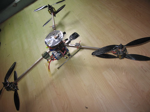
Not much space if you're going on holiday with the family in a Renault Clio. This design fits into a 52cm toolbox with transmitter and all accessories.

Just thought I'll share my crash resistant design that has evolved through many drops and repairs. On impact it is now usually just a matter of replacing a rivet or a prop. The electronics and battery can quickly be removed for installation on another airframe.

The props are 15" RC timers and as shown I get about 23min flight time with a slightly damaged 5000mAh 4cell Lipo at 1500m above sea level, 25 deg C.

The difference in spacing between front and rear props doesn't have a noticable effect on stability and it flies waypoints very well.

I'll post basic plans if anyone is interested or if you want an airframe let me know.

Update: Plans for the airframe

Template.PDF 

Tubes.PDF  

Plate%20DXFs.DXF

Read more…

Marcy 1 with the lights on


Finally got her to fly with the lights on. There are a lot of problems with lightbulbs reflecting on reflective surfaces. These problems never happened with IR, but IR should be no different.

Detecting the XYZ of a spinning object with 1 camera in high shutter speed mode is really hard. It would be easier with 2 cameras.

There is a new takeoff algorithm, relying on hard coded throttle for a given battery voltage to instantly leap off the stand. It's a very unstable system. Technically, it should be more stable than the previous throttle ramping algorithm.

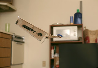
marcy1_79.jpg

marcy1_80.jpg

marcy1_81s.jpg


 So the 70fps framerate, the lack of need for a USB hub, & the lower computational load made the board cam irresistible. Despite everything flying perfectly, it was time to rebuild it again.

The board cam immediately had new problems. The radio & camera don't always initialize. It helps to leave the board powered off for a while before restarting it, but it's a real problem if it is to automatically boot on the raspberry pi without a command line to drop kick it. There would only be power cycling after observing the failure on a tablet. This didn't happen with the last build of exactly the same board, but the last build had 4 more PWM's & no camera.

Also, there are a lot of tiny cables flexing. There wasn't any notable improvement in flight. The picture had a much more refined oval & probably more accurate coordinates but the flight was equally unstable.

With all the knowledge gleamed over the last year, the ultimate vision system would now use visible light, dual board cameras on separate turrets & separate USB connections producing 320x240 at 70fps. That would give the best velocity measurements. It would be nice if an IR board cam was easily obtained, but the lack of such a camera & the reduced power needs of visible LED's make IR impractical.

Without the instant velocity measurement of doppler shift that GPS provided, all indoor vehicles have suffered from delayed velocity measurement. The only solution is to increase the framerate to make the velocity measurements as close to realtime as possible, but never as good as doppler shift.

There were 2 major software changes:

The autopilot since 2009 exclusively used a binary integral. It would add all or none of the feedback constant, regardless of the error. That produced very fast response to changing weather, but created lots of oscillation. Changing it back to a proportional integral which scaled the feedback constant based on the error greatly reduced the oscillation.

The autopilot has always accumulated cyclic trim in world frame & translated it to copter frame. That compensated for wind as the copter turned, but indoors there is no wind & the trim is entirely due to vehicle balancing. For the 1st time, the cyclic trim was stored only in copter frame & the turns on the Syma X1 got a lot more stable.

The Syma X1 has a problem of gyro drift & uneven motor heating causing massive trim changes. It has always needed more aft pitch as the flight wore on. Normally, you want the vehicle as balanced as possible, so the trim is only due to wind.

There is a case for cyclic trim in copter frame for an outdoor vehicle, to compensate for balancing, but no way to differentiate between balance & wind.


The 1st flight using the 70fps 320x240 board cam. It wasn't tuned & oscillated.  The velocity measurement needs to be at least 7Hz before the oscillation becomes bearable.


Looking up from below in slow motion gives the impression of a long gone vehicle, but the reality is she's never been more than a week from being flyable, since 2011. There are plenty of other vehicles which will never fly again. With the flight software now working on raspberry pi, there is every intention of having a self contained flying system that always works.

The current vehicle was mostly developed in April, 2011. Only the takeoff stand was improved in Jan 2012. The machine vision system saw development in Summer 2011, Jan 2012, & the last week with conversion to a board cam.

Since monocopter development began, in 2010, there has never been an onboard camera. The plan is now to stick a basic 320x240 wifi camera board on her, in addition to the existing flight computer board & ESC. The previous plan was to replace the flight computer with the camera board & have all data on wifi, but the camera board needed to be more modular. Wifi will now just carry video & somehow automatically associate with the raspberry pi access point.


The 2nd Marcy 1 took to the air. This one is loaded down with the POV LEDs.


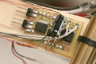
Visually the same, but mostly redesigned. The POV processor & mane processor now read the radio directly instead of the mane processor passing on data to the POV processor. It was 1 more wire but much simpler code. Even though it was built in July, this was the 1st time this airframe did POV. The motor is immediately getting too hot, melting through the propeller.

The fancy blob detection had to go for POV to work. It's back to a simple threshold, exactly like the nighttime only version. IR vision would allow it to use blob detection.

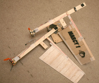
marcy1_82.jpg

marcy1_83.jpg

marcy1_84.jpg


There was supposed to be a 3rd Marcy 1, with an onboard camera. It's possible to get a very small, wireless camera, but the only fabrication possible in the apartment is a large wireless camera.

Also, if it has 802.11 on it, it's a drag to have to carry around a ground station to control it instead of controlling it directly from a tablet. It's necessary, because 802.11 isn't reliable enough to control it & having 1 system that supports an autopilot & manual control is easier than having 2 unique systems for autopilot & manual control.


 The trick with Marcy 1 is once she's flying with the lights on, the thrill from such a strange device hovering subsides, & she gets real boring.

Read more…
3D Robotics

Berkeley rejects proposal to ban drones

3689492404?profile=original

My faith in our political process in Berkeley is restored. The proposal to make the city a "No Drone Zone" was rejected. Among other things, wise minds reminded the council that cities don't control their own airspace - the FAA does.

From Berkeleyside:

At its meeting last night, the Berkeley City Council rejected a recommendation from the Peace and Justice Commission to establish a No Drone Zone in the city. Instead, the council referred the issue to three commissions — the Peace and Justice Commission, the Police Review Commission, and Disaster and Fire Safety Commssion — with guidelines for public safety agencies’ use of drones to be reviewed at a future council workshop.

During public comment more than a dozen people spoke in favor of the Peace and Justice Commission proposal, which would have banned all drones except for hobbyist use (and those would have been restricted to drones without cameras).

Councilmembers, however, argued that there could be some beneficial uses for drones.

Councilman Jesse Arreguín agreed that the technology could potentially infringe on privacy rights, and said policies to prevent that were needed. But he suggested that drones could be valuable for public safety in the event of disasters, searching for missing persons, rescue operations, and when police are in pursuit of a known suspect.

“Drones have been used for very bad purposes, but drones can serve a purpose,” agreed Councilman Laurie Capitelli.

“Berkeley doesn’t have jurisdiction over its airspace and we can’t enforce it unless we buy Patriot missiles to shoot things down,” said Councilman Gordon Wozniak, who also pointed out the potential beneficial uses of drones.

Councilman Max Anderson said it was important to have clear guidelines developed for drone use.

“Unless we are restrictive and proscriptive about how they are going to be used, we are going to be screwed,” he said.

The Council also voted to send a letter to the Alameda Board of Supervisors requesting they delay any purchase of a drone until Berkeley’s deliberative process was over.

Read more…
3D Robotics

And now, a Lego ArduCopter!

3689492324?profile=original

My life has now come full circle. I got started in this madness with a "Lego UAV" (a regular RC plane with a Lego Mindstorms autopilot that I built with my kids). I then moved on to more appropriate platforms, ending up with multicopters. Now Gary Mortimer has found a dad who's created a Lego ArduCopter!

The first images that I saw of this Lego quadrocopter frame raised a smile. On contacting Ed Scott, C#/C++ developer by day and Lego flying robot wrangler by night I was impressed. I also recognised a pattern, last week one of my sUAS was engaged in parachute dropping duties for my sons 9th birthday party. Credit must go to Ed’s son’s Nicholas and Joshua Scott who designed the worlds first flying robot made out of Lego!

Equipped with a Go Pro camera to record it’s surroundings and a first person view (FPV) camera and transmitter sending back live video images to its pilot the Lego quadrocopter is an advanced machine. It is kept on an even keel and able to navigate waypoints via GPS thanks to an APM 2.5 autopilot from 3DR.

When I caught up with Ed he had the following to say:-

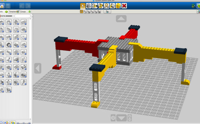
My son kept asking me to attach lego things that they made to my GAUI 330x we had lots of fun making there creations fly. One day I was on a field and crashed my GAUI, one arm was completely broken off, I went home and that night I remembered my son using, LEGO Digital Designer (LDD), so I though maybe my sons and I could make a quad and use the motors from the GAUI. If we could automate it we could make the worlds first flying LEGO Drone.

We came up with a design using LDD that had strength and we would be able to open the top to get at the wires. Then we used LEGOs Pick A Brick to order the LEGOs.. The Quad was built 100% by my boys and then I helped them glue it together together. Since we have been flying it we have had some very hard landings and a few flips, except the legs breaking off it has been superb and very very strong. I plan on changing out the legs from the “LEGO window frame” to a “2×2 brick” to give it even more strength.

Most people go to their favourite hobby store to get parts for their UAV, I go to my kids playroom.

Want to make your own and don’t have a bucket of Lego handy, test your design skills  in the software Nicholas and Joshua used http://ldd.lego.com/

Well done to all involved another worthy entry in the UAVs Got Talent category.

Read more…

DJI style case for 3DR Gps Modules

3689492193?profile=original

New to the ArduCopter world, so here goes.. finished my first hex build a few weeks ago, so have been working on a few cosmetic upgrades.. It's a bit silly but I like the little puck gps modules that DJI has, so decided to make and share a similar design of my own with everyone..

If you have a 3d printer grab the files from the link below, you can also use a service such as shapeways to print the parts needed, and if there is enough demand I could possibly kit up some units with all the pieces.

The Parts

http://www.thingiverse.com/thing:38318

The Assembly Guide

https://docs.google.com/presentation/d/1TU4vnMtWU1QqRpU-9ZGfMhHdiytcBT4WMF3N_ayuv2A/edit

enjoy, more parts coming soon... 

3689492279?profile=original

Read more…

Mans best friend...A Drone!

If there is anything I look forward to more than updates from Darpa, its updates from Boston Dynamics.  They are really doing some pretty innovative things in the way of robotics there, and yet here is another example.  My arducopter is jealous.  

Read more…
3D Robotics

3689492254?profile=originalFrom famed venture capitalist Steve Jurvetson:

A quad ‘copter from Chris Anderson, with Go-Pro underbody gimbal and a sensor array for landing that is so very clever in the repurposing of consumer hardware to replace expensive and heavy radar units like they used on Apollo. A great way to test the control algorithms for automated landing. Like Apollo, the landing would occur at lunar daybreak (maximum shadows for surface feature contrast, and a 14 day window of solar flux).

The tech challenge I am working on is how to survive the 14 day lunar night at -150°C. Batteries freeze rather destructively. The only Apollo instruments to survive the night had nuclear batteries (like Curiosity). I am thinking Solar Junction solar cells, Everspin rad-hard/soft-error-immune MRAM, and a super cap or maybe LiIon electrolyte from eSionic which might survive the temp cycling. Or perhaps a Solicore solid electrolyte from ORNL. Has anyone tested the other elements (processor, PCB interconnect) through those extreme temp cycles?

Part of a very fun update tour of Moon Express at NASA Ames today.

It's simulating something similar to this:

3689492244?profile=original

Read more…

3689491949?profile=originalAll the work below is done with the objective of finally being able to fly multiple MAVs/UAVs all in autonomous mode communicating with one another to achieve meaningful goals (Like quickly scan a particular area for identifying a target etc). The "Human pilot" flying in manual mode is optionally kept in the loop. Everything below is open source, so feel free to use/modify/extend :)

I am not sure if anyone else here in the community is working on carrying out such cooperative missions(like Leader-Follower, Orbit follower, Cyclic Pursuit etc) although theoretical work on it has been around for a while in many research papers. If nobody has worked on it yet, here is a fresh start, else, do comment below about your projects.

Currently, what we have here is a HIL simulator for these cooperative missions for 3 MAVs and we wish to now implement these in flight.    

A framework for Hardware in Loop Simulation (HILS) of cooperative missions in autonomous miniature aerial vehicles (MAV) using open source Ardupilot-Mega based hardware and software platform has been implemented. Ardupilot Mega (APM) is an Arduino based commercial autopilot board for stabilization and navigation of individual MAVs. Our framework extends its features to support HILS of cooperative missions for multiple MAVs by facilitating inter-aircraft and aircraft-ground station communication.

The framework has a loosely coupled design which isolates the high level planning algorithms from the rapidly evolving low level autopilot routines. It is designed as a natural extension to the various flight modes (Manual/Return-to-Launch/Circle/Waypoint navigation) already present in Ardupilot-Mega platform and can be switched between them seamlessly. Cooperative mission mode is triggered through switching to "Guided Mode".

Inter-aircraft communication is done using Xbee API protocol which facilitates unicasting custom message packets to-and-from any aircraft of the cooperative system. The Xbees are also used by all the aircrafts in the HILS to communicate with the QGroundControl Station (qGCS) using the widely compatible MAVlink protocol. This makes the framework compatible with any other GCS supporting MAVlink protocol.

Since all the communication between various nodes of simulation is through Xbees in API mode, it makes the framework readily extendable for flight testing of the cooperative algorithms in real flights. The hardware in this HIL simulation comprises of the APM autopilot controller board and Xbee modules in API mode. The APM board runs both the low level autopilot software and the high-level cooperative algorithms. Xbees perform the inter-aircraft and aircraft-GCS communication. The sensors and actuators are being simulated in this HILS framework. Open source flight simulation software Flightgear is used to simulate the flight dynamics. The sensor/actuator information is exchanged
between the autopilot board and Flightgear over a serial port. 

In short :

GCS used : Qgroundcontrol GCS

Autopilot Used : APM 1.4 (without Oilpan)

Communication modules : Xbee Pro in API mode on all aircrafts and GCS

Inter Aircraft communication : In Xbee API protocol

Aircraft GCS communication : MAVlink v0.9 embedded in Xbee API header and Footer

Flight Simulator Used : Flight gear, Aircraft used : Rascal 110 and C172p (JSBsim)

No. of MAVs in the cooperative mission simulated : Upto 3 till now, can be easily extended to more.

Cooperative missions performed up untill now : Leader follower for 3 MAVs, Orbit Follower for 3 MAVs, Cyclic Pursuit for 3 MAVs

Here are a few snaps of qGCS during various cooperative mission HIL simulations:

Leader Follower for 3 MAVs:

MAV1 : Autonomus Waypoint Navigation mode

MAV2 : Continuously follows MAV1

MAV3 : Continuously follows MAV1

3689492079?profile=original

View from another angle of the same mission.3689492202?profile=original

Orbit Follower for 3 MAVs

The orbit center(lat,long,alt) can be set for any of the 3 MAVs through clicking on APM Missionplanner "Fly to Here" option which sets it as the orbit center for that MAV and also sends this orbit center information to rest of the MAVs in the simulation with then accept it as there orbit center information. Thus all the aircrafts immediately start to converge into orbits around that center.

3689492113?profile=original

Another angle of view for the same simulation.

3689492217?profile=original

The major part of APM firmware is kept essentially the same, except for a few additions. This flowchart below explains what we have tried to do :

3689492128?profile=original

Since we were using APM1.4 without the Oilpan, we started with the firmware provided by ardupilotdev ArduPlane_228xp2.zip and made all the additions/changes in it. We are in an effort to port everything to the latest APM firmware so that we can test the setup in flight. We also have to shift from the old MAVlink 0.9 to MAVlink 1.0.

Here are the required codes for the leader follower mission (Edit it using Arduino 0022 relax patch)

I seem to have exceeded a space limit of some kind(can't seem to attach anymore files!), I'll attach the codes as comments below.   


This work was carried out by the combined effort of Swaroop Hangal and Bharat Tak under the guidance of Dr. Hemendra Arya.

Read more…

Well, I finally got my quadcopter w/ APM 2.0 built and flying, and crashing.  I was so happy to be flying that the I think I ran below voltage threshold on ESC, and lost power.  I still need to confirm in logs.  In any case I need a new frame.  Here's some photos (before crash) and video (crash at end).  Any advice would be appreciated, I made a lot of educated guesses on components.

http://youtu.be/lgjSy6QCz0I


3689492027?profile=original

3689492038?profile=original


Specs:

Frame: HobbyKing quadcopter frame V1  (3 arms broke on crash)

Motors: NTM 28-30A 750kv

ESC: Turnigy Plush 25A

Props: Slow Fly 12x45

Controller: APM 2.0 with Arducopter 2.8.1

Radio: Turnigy 9x, flashed with er9x

Battery: 2200mAh 3S 25C

Power distribution: 3DR power distribution board

Video: GoPro Hero

Read more…

What I am up too

Currently operating my first UAV, a DJI 450 with standard equipment (motors, Esc, NAZA, GPS). I'm using a 9 channel JR receiver , EZOSD, 5000 MAH 45C battery pack, Sony 650 line camera with a  pitch axis adjustment that I fabricated that allows me to adjust from the ground, immersion 500 MW 5.8 GHZ transmitter, GoPro 3 Black, LED light system with controller. CF extended legs.

Ground equiment includes Fat Shark goggles with immersion 5.8GHZ receiver module, and a immersion 5.8 GHZ UNO feeding a 9.5 inch LCD monitor and a DVR that records MP4 to SD. I like to record the video transmitted back to the LCD monitor which I usually let someone else views while I fly by googles. That way, I can review the flight and look at the OSD data, yet I'm also recording good HD video with the GoPro


I'm looking forward to building an ArduCopter now, and have ordered what I need. I'm looking forward to learning about flying pre planned courses, and Fuller control of camera work and some of the other features of the APM that may be coming.

Read more…
3D Robotics

3689491913?profile=originalJust another in the long list of interesting civilian applications. Described here:

After more than a year of developing and adapting equipment that would allow us to explore the missing dimension, it is time to announce FG+SG's new service of collecting aerial images, providing a complementary form for viewing architecture against the landscape without the associated costs of an aeroplane or helicopter.

This past year we modified several cameras until we found the ideal match for every type of flying, having experimented in parallel various ways to control them remotely. We redesigned our drone and manufactured new parts. We experimented with different motors and propellers until we had a machine made of carbon fiber that is lightweight, robust and autonomous enough to guarantee optimal flying conditions in order to obtain the images that our clients want.

The photographs are by Fernando Guerra, who, together with the help of our "pilot", our newest team member, guarantees the desired framing and quality.

In allowing project images to be taken from the air, be it of a building, part of a cityscape, or a golf course, this new option complements the traditional photo shoot with a new dimension.

Information about this new service can be found at ultimasreportagens.com, the portuguese library for architectural projects.

3689492019?profile=original

(Via PopSci)

Read more…
3D Robotics

Synthetic aperture radar for $360

3689491965?profile=originalFrom Hackaday:

A few profs from MIT’s Lincoln Lab are giving those poor MIT undergrads something to do over winter break: they’re teaching a three-week course on building a laptop-powered radar system capable of radar ranging, doppler, and synthetic aperture imaging. Interestingly, the radar system that teams will build for the class has a BOM totaling $360, and they’re alsoputting the entire class online if you’d like to follow along and build your own.

From the lecture notes from the course, the radio system is made out of an off-the-shelf  LNA, oscillator, and  splitter. By connecting two coffee can ‘cantennas’, it’s possible to record a .WAV file from the signal coming from the radar and use MATLAB to turn that audio signal into a Doppler radar.

It’s a very ambitious project that goes deep down the rabbit hole of RF and analog design. One of the lecturers made a YouTube demo of the radar in ranging mode; you can check that out below.

Read more…

Hexapod Hexacopter

211__600x_hexawalker_0331.jpgThe evolution of Multicopters into fully autonomous systems is progressing at an alarming rate! 

Here we have a Hexacopter with a Hexpod for landing gear - allowing omnidirectional ground and air based movement. I think this is very very cool! Now all it needs is a few cameras and you can have a system that could determine whether it should go over or under obstacles. I brings whole new possibilities to search and rescue operations. 


Thoughts?


Original posting:

http://madlabindustries.com/hackerspace/projects-2/hexapod-quadcopter/


Well done Mad Labs!

Read more…