http://www.hobbyking.com/hobbyking/store/__19335__Skywalker_FPV_1680mm_ARF.html
All Posts (11086)
Sort by
This is a bit off-topic, but my MakerBots are some of my favorite open source hardware and 3D printers are a cool prototyping tool that we use a lot at 3D Robotics. The New York Times ran a great diagram of how they work today (click for larger size):
 The FPVRaptor is an attractive and superbly designed FPV platform with a a host of neat features that make this model one of the best in its class.
For toughness and reliability, the model features a blow moulded fuselage which utilizes Nylon and is virtually indestructable, the flying surfaces are all made from tough EPO foam. From point of view of practicality, the wings are plug in and the model requires no glue for assembly, everything simply screws together. The outer canopy is purely for looks and is used when the FPVRaptor is flown as a glider, it unclips in seconds to reveal a camera ready platform, complete with a pan/tilt servo mounting hole that has been pre-moulded. This large camera platform/wing cover is secured by a quick release latch and once removed, reveals huge canopy area for mounting batteries and FPV equipment onto a pre-fitted ply plate. All servos, motor & ESC are of course pre-installed.

The plug in wings have mouldings for adding flaps if desired and there is also a moulded C of G indicator on the underside of the wing for quick pre-flight checks. There is no doubt that this is a superbly designed, high quality FPV model at an excellent price. It would be fair to say that it is more attractive to look at than most FPV platforms, not to mention much tougher, the FPVRaptor will give the RC Pilot hours of enjoyment for many years to come!
Specifications:
Wingspan: 1600mm
Length: 1044mm
Flying Weight: 950g
Motor: 2812 1400kv brushless Outrunner
ESC: 30A w/BEC
Servo: 9g x 4
Price for this Plug and Fly plane (just add your rc gear, a battery and fpv stuff) is US$ 73.45
More information at http://www.hobbyking.com/hobbyking/store/uh_viewitem.asp?idproduct=18764
From Robots.net:
The explicitly named “Bioinspired Integrated Multi-Modal Locomotion” is a project of Carnegie Mellon’s University, NanoRobotics Lab. The module use a mechanism with folding bars that are spring loaded via a system of wired similar to a human knee’s tendons. This mechanism is able to rotate lengthwise. Pointing downwards acts like a spring that launch the robot and at its trajectory highest point it rotate and becomes a wing shaped surface that enables it to glide. It is a clever way to use the same thing for two very different purposes. Read more at the project’s website:nanolab.me.cmu.edu/../MultiModalLocomotion/
I've been checking out Upverter, which is a YCombinator startup that's aiming to the the "GitHub for electronics" and open source hardware. So far it looks like they're very much on the right track, with excellent social and workflow tools built into a Web-based schematic editor.
They don't do PCB design yet and the parts library is still relatively small, but it's worth checking out. It would be very cool if they can find a way to be compatible with the new Eagle V6 XML files. That way you could use Upverter as a version control repository/collaboration environment, while still using Eagle's best-of-class libraries and PCB design tools.
Look what showed up in my Google ads! The APM-ready Scout UAV carbon fiber quadcopter frame is now available.
$360 complete with ESCs, motors and props seems like a very good deal.

The Eaglewing has been designed specifically for FPV and as you would expect for an FPV platform, there is a generous wing area coupled with a pusher motor configuration. The large canopy you would also expect, but the clever part is that it can be configured in a variety of ways to suit your FPV equipment, with a large clear over-canopy that can be cut to the desired size.
Specifications:
Wingspan: 1500mm
Length: 980mm
Flying Weight: 960g
Price: US$ 49.99 / 57.20 (USA) - Prices might vary depending on your Hobbyking membership level
More information at Hobbyking: hobbyking.com/hobbyking/store/uh_v...roduct=19337

A drone from the Swiss army crashed on tuesday morning. Interesting to see how quick the army communicates with a photograph of the incident. At least it 'landed' on the airstrip.
 For those into board design, Eagle is a nice free (for non-commercial use) option which has, until now, lacked XML structure. Eagle will soon support importing & translating from other formats among other productivity improvements. Until now, this compatibility issue has prevented myself and likely many others from using Eagle as a primary PCB design tool. I believe the DIYD crew also uses Eagle for designing Arduboards.
From CadSoftUSA via Make
 The ADXL345 is a small, thin, low power, 3-axis accelerometer with high resolution (13-bit) measurement at up to ±16 g. Digital output data is formatted as 16-bit twos complement and is accessible through either a SPI (3- or 4-wire) or I2C digital interface. The ADXL345 is well suited to measures the static acceleration of gravity in tilt-sensing applications, as well as dynamic acceleration resulting from motion or shock. Its high resolution (4 mg/LSB) enables measurement of inclination changes less than 1.0°. Several special sensing functions are provided. Activity and inactivity sensing detect the presence or lack of motion and if the acceleration on any axis exceeds a user-set level. Tap sensing detects single and double taps. Free-fall sensing detects if the device is falling. These functions can be mapped to one of two interrupt output pins. An integrated, patent pending 32-level first in, first out (FIFO) buffer can be used to store data to minimize host processor intervention. Low power modes enable intelligent motion-based power management with threshold sensing and active acceleration measurement at extremely low power dissipation.
Features:
Ultralow power: as low as 40 μA in measurement mode and 0.1 μA in standby mode at VS = 2.5 V (typical)
Power consumption scales automatically with bandwidth
User-selectable resolution :
Fixed 10-bit resolution
Full resolution, where resolution increases with g range, up to 13-bit resolution at ±16 g (maintaining 4 mg/LSB scale factor in all g ranges)
Embedded, patent pending FIFO technology minimizes host processor load
Tap/double tap detection
Activity/inactivity monitoring
Free-fall detection
Supply voltage range: 2.0 V to 3.6 V
I/O voltage range: 1.7 V to VS
I2C interface
Measurement ranges selectable via serial command
Bandwidth selectable via serial command
Wide temperature range (−40°C to +85°C)
10,000 g shock survival
Documents:
Schematic: http://www.flytron.com/pdf/ADXL345_schematic.pdf
Datasheet (ADXL345): http://www.flytron.com/pdf/ADXL345_datasheet.pdf
Example Code (Arduino): http://www.flytron.com/pdf/ADXL345_example_code.zip
Price is US$ 24.95 (on sale, might not take long)
More information at the Flytron website: http://store.flytron.com/sensors/143-adxl345-accelerometer-breakout-board.html

HMC5883L is a 3-axis digital compass from Honeywell. Communication with the HMC5883L is simple and all done through an I2C interface. There is no on-board regulator, so a regulated voltage of 2.16-3.6VDC should be supplied.
This breadboard-friendly board breaks out pins to a 4-pin 0.1" pitch header. We've also put two 10k pull-up resistors on the I2C lines.
Features:
Simple I2C interface
2.16-3.6VDC supply range
Low current draw
5 milli-gauss resolution
Dimensions:
15.2x15.2 mm
0.5 gram
Documents available for download:
Schematic: http://www.flytron.com/pdf/HMC5883L_schematic.pdf
Datasheet (HMC5883L): http://www.flytron.com/pdf/HMC5883L_datasheet.pdf
Arduino Example code: http://www.flytron.com/pdf/HMC5883L_example_code.zip
Price is US$ 13.95 (sale price, not sure how long it holds...)
More information at the Flytron site: http://store.flytron.com/sensors/142-hmc5883l-triple-axis-magnetometer-breakout.html
I'm going to be speaking at the Wired UK conference in London on Oct 13 and they want to see an ArduCopter demo. I can't bring on with me. Are there any ArduCopter pilots in the London area who would like to do an (indoors) demo at the conference? I can get you free admission to the whole thing (plus you get to hang out with me ;-))
PM me if you're interested.
These instructions explain how to set up a Spektrum DX7 transmitter for 6 different flight modes, using just the 3 position Flaps switch (in combination with the Rudder switch). This way you'll use just one channel for the flight modes and leave the Gear and Aux2 channel open ...
(note that you have to use the DX7 in "airplane mode", not in "heli mode" to fly a quadcopter)
- switch on your remote while pressing SCROLL DOWN and SELECT
- go to "D/R Switch Sel" menu (with the SCROLL UP/DOWN button)
- select "Com Rudd" by pressing the INCREASE button
- go to the "Input Select" menu (with the SCROLL UP/DOWN button)
- press select until you reach "Flap:", make sure it is set to "System" (you can change the setting with the INCREASE button)
- press SELECT
- set "Flap Trim" to "Inh" by pressing the INCREASE button
- switch off the remote
- switch on the remot
- Press SCROLL DOWN + SELECT to access the programming mode
- Go to "Mix1" (with the SCROLL UP/DOWN button)
- go into the menu of "Mix1" by pressing the INCREASE button
- Select "Flap" > by pressing the INCREASE button
- press SELECT to jump to the second position and select > "Flap" by pressing the INCREASE button
- press SELECT
- Set rate to "+100%" and "-50%" (with the INCREASE/DECREASE button, you'll have to put the FLAP switch in the "N" position for the first value and into the "2" position to set the second value)
- press SELECT
- Set SW to "Mix" by pressing the INCREASE button
- press SELECT
- set offset to "10" by pressing the INCREASE button
- Go to "Flap Sys" menu (with the SCROLL UP/DOWN button)
- set Flap Norm = UP to "46%" (with the SCROLL UP/DOWN button)
- press twice SELECT
- set Flap Mid = DN to "8%" (with the SCROLL UP/DOWN button)
- press twice SELECT
- set Flap Land = DN to "100%" (with the SCROLL UP/DOWN button)
- press twice SELECT
- set Auto Land to Inhibit (with the SCROLL UP/DOWN button)
connect now your APM to the Ardupilot Mega Planner, go to the setup page and assign different flight modes to the switch combinations of your remote.
I like to have easy access to the simple mode (just to get very quick out of a difficult situation) which is the reason why I have two switch combinations programmed for simple mode. I have set it the way that simple mode is always selected if the "Flaps" switch is on "N" (away from me), no matter if the "Rudder" switch is on or off. This way I have just 5 modes accessible, but I can very easy and quick switch back to simple mode.
(this is based on the blog post by Limebear)
www.diesunddas.co.uk
Dear Friends,
today i doing my first flight with new revision of VR Dragon.
Dragon components are :
VR Brain (Multipilot32 ).
VR Imu Full
6 x 50 Amp Motorius ESC
6 x 13 APC propeller.
6 x Turnigy Motors
Carbon Fiber Frame.
The first gimbal tested is PhotoHigher AV 200.
This kind of configuration can
I put on Dragon for the test 2 kind of camera Panasonic SD90 and Canon EOS 600D.
During my test i found some problem on rolling shutter on SD90 . The Canon EOS 600D don't have any kind of problem it is perfect camera.
The RTF Kit will be available at the end of october if you need more information contact me at : lasernav@gmail.com
Original post : http://www.virtualrobotix.com/profiles/blogs/vr-dragon-2-0-first-flight-with-gimbal-firmware-arducopter-32-rev
More picture for building log : http://www.virtualrobotix.com/photo
Here is the laser cut acrylic mocked up...the laser doesn't do well with G10 so I had to find someone that would cut it for me until I build my own router.
Here is the main plate with the carrier boards. I have the vibration mounts(black things) supporting the carrier boards. The APM is mounted on top of the first carrier board with the Xbee on the very top.
here is the bottom half of the copter. the battery tray is on the bottom. the battery slides in between the two pieces.
and lastly, here are both pieces together. the arms will sit between the two big main plates.
i have one g10 piece to cut by hand. i'll post more pics when it's done.
Check out 2:22 Diydrones makes the engineering.com news. (matternet)
https://www.youtube.com/watch?v=FnB9EHIpPK0
Just passing it along.

This is a simple breakout board for the BMP085 high-precision, low-power barometric pressure sensor. The BMP085 offers a measuring range of 300 to 1100 hPa with an absolute accuracy of down to 0.03 hPa. It's based on piezo-resistive technology for EMC robustness, high accuracy and linearity as well as long term stability. This sensor supports a voltage supply between 1.8 and 3.6VDC. It is designed to be connected directly to a micro-controller via the I²C bus
This breadboard-friendly board breaks out all pins of the BMP085 to a 4-pin 0.1" pitch header. We've also put two 10k pull-up resistors on the I2C lines.
Features:
- Digital two wire (I2C) interface
- Wide barometric pressure range
- Flexible supply voltage range
- Ultra-low power consumption
- Low noise measurement
- Fully calibrated
- Temperature measurement included
- Ultra-flat, small footprint
Dimensions:
- 15.2 x 15.2mm
Various documents are available:
- Schematic: http://www.flytron.com/pdf/BMP085_schematic.pdf
- Datasheet: http://www.flytron.com/pdf/BMP085_datasheet.pdf
- Arduino sketch example: http://www.flytron.com/pdf/BMP085_Example_Code.zip
Price is US$ 18.95 (on sale at time of writing).
More information at the Flytron website: http://store.flytron.com/sensors/141-bmp085-breakout-board.html
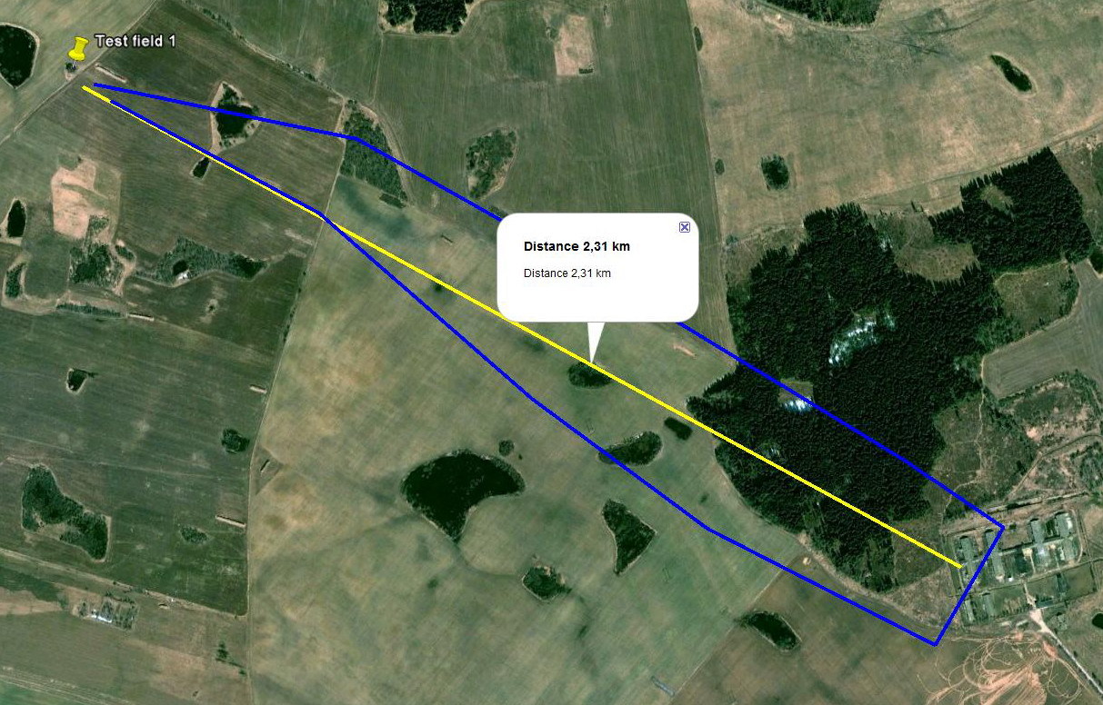
In the last few days I make some test fly for short distance.
On ground station we use YAGI 16 dBi antenna without tracking system, connected to XBee modem with 5 meter cable.
For distance ~2,5 km system work very fine...
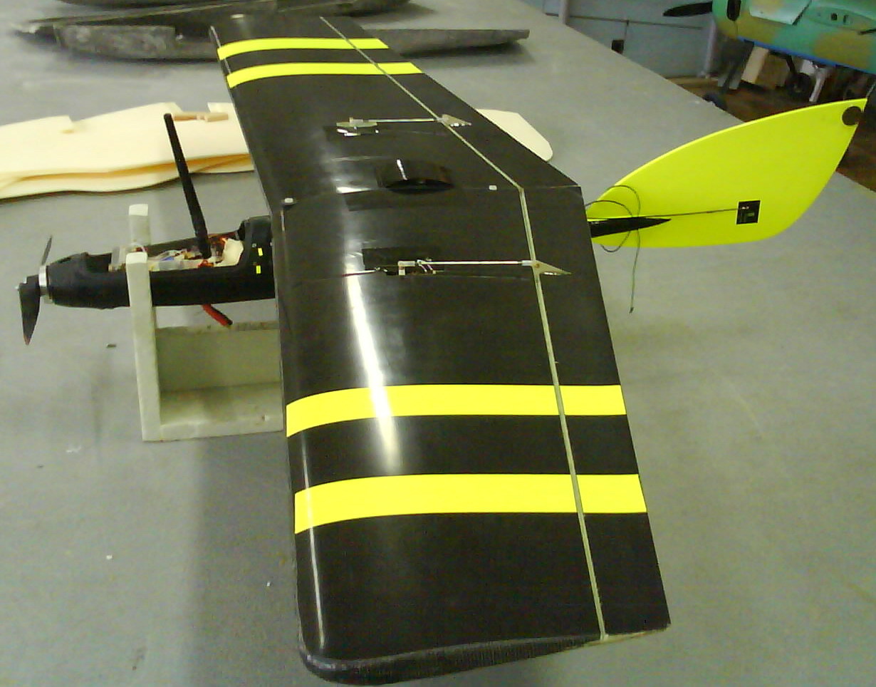
Mamadu take a new fin for better yaw stability.
This is the third part of a three-part posting on chip design and how to reconcile it with the open source and DIY movements. (Part 1 is here and part 2 is here.) In this part I will discuss economics- How much does it actually cost to fabricate a chip? Can batching be used to make the cost accessible to a group of (hypothetical) casual chip designers?
Masks
Once a chip design is “taped out”, the chip foundry who manufactures them first creates a set of masks- anywhere from around 15 to upwards depending on the design and the manufacturing process. These are for a photolithography process that is vaguely similar to those used in PCB manufacture, however for chips the masks are both more precise and more expensive.
I won’t give exact costs or list specific foundries, but I’ve seen masks cost anywhere from under $10k to over $50k for a complete set. This is for a 0.5um or 0.6um process. Obviously the masks for the latest 32nm process would be much more.
Reticle
Typically in chip design the foundry creates a set of masks for a “reticle”, a box-like region that gets replicated over and over across a whole wafer using a stepping process. A wafer itself is a disc of silicon less than a millimeter thick but generally tens of centimeters in diameter.
The typical reticle size I use is about 21mm x 21mm. (The masks themselves are much larger than this but the image is optically reduced during the manufacturing process.) You can fill up that reticle pretty much any way you want- you can put in a single 21mm x 21mm chip. If your chip size is just 2mm x 2mm you can put in a 100 of these into the reticle, so every reticle gets you 100 chips. You could also put in 100 different designs. This is where batching would come in.
Batching
There are companies that provide batching services. One of the oldest is the MOSIS service, run by ISI of the University of Southern California. MOSIS was set up originally with DARPA and NSF grants as a way to bring chip design to universities, and give students the ability to design and fabricate a chip, either as a classroom exercise or for a research grant. MOSIS also offered their services to industry. To this day they still offer these services and actually serve as a “store front” for several major chip foundries (ON-Semiconductor, TSMC, IBM, and others) for customers who want to prototype chips without paying for a whole set of masks.
The economics are essentially that everyone shares the cost of the tooling. Let’s say a mask set for a reticle has 10 different designs and cost $20k to make (a somewhat made up number)- that comes down to $2k per design- a much more reasonable number!
There are other services similar to MOSIS, and there are also individual companies that offer “multi-project runs” specifically for smaller customers that want to batch-prototype chips. So the batching concept is clearly established. In fact, whenever I do a run of silicon at Centeye I also place multiple designs on one reticle to get the most for my money.
Hypothetical Cost Breakdown
So let’s suppose a company wanted to get into the chip batching business. Let’s say the company decides to accept 2mm x 2mm size chips, and place 100 different designs onto a reticle. (The remaining 1mm slivers could be used for test circuits and quality control…) Looking at pure costs alone (e.g. neglecting stuff like “overhead”, “labor”, and “profit”), the numbers might look like this:
Mask set for a 21mm x 21mm reticle: $20,000
6”/150mm diameter wafers, set of 10 (approx 30+ reticles per wafer): $10,000
Dicing the wafer up into chips: $500 per wafer
First consider prototype quantities- I don’t know of any foundry that will make a single wafer- typically a set of wafers are manufactured in case one or a couple of them fail quality assurance inspections. For initial prototyping you would end up dicing just one wafer. Next comes packaging- most customers are not equipped to work with bare die, so they would probably want the chips in a DIP or similar package that they can then solder to a board or press into a breadboard- this would probably cost at most $20 per chip, at cost. Total cost per customer: ($20k + $10k + $500)/100 = $305 for about 30 chips, plus $20 per chip packaged.
Next let’s consider a slightly higher quantity price break, by dicing up all 10 wafers. The total cost per customer rises to ($20k + $10k + 10 x $500) = $350 for about 300 chips, not including packaging.
These numbers are encouraging. Of course, we have to assume 100 such customers can be found, and we have to consider the other costs to stay in business, but the above numbers should give you a starting point.
So where does that put us?
Once we factor in the cost of doing business, we get upwards to a thousand dollars for a batch-run prototype chip. This is a stiff amount compared to a batch-fabbed PCB. But it is not impossible- This amount is easily within the budget of a Kickstarter project, and there are hobbyists that would be willing to spend this amount on a chip fab. Certainly small companies could spend this amount. Also note that due to the nature of the chip manufacturing process, there could be several hundred individual chips available for use (or sale) if the design works. (There are a number of caveats, of course, which I didn’t mention here, but can discuss below if there is interest.)
I think one of the challenges, though, is overcoming the fear of spending money on a fabrication that doesn’t work. Getting back a PCB that doesn’t work is never fun; the stakes are higher for chips because of both the higher cost and the long lead times (generally six weeks or more). This is where the combination of good design tools and good design practices can help out- I think the “abstract layout” workaround mentioned in my last post, properly executed, could make “probability of success” sufficiently high for the DIY crowd.
This is how it worked for my DX7,
I use various switch combinations of the FLAPS and the GEAR switch which will give you 6 modes;
(note that you have to use the DX7 in "airplane mode", not in "heli mode" to fly a quadcopter)
- Press SCROLL DOWN + SELECT to access the programming mode
- Go to the "Travel Adjust" menu with the SCROLL UP/DOWN button
- click the SELECT button till you reach "Flap", then set "Flap" to "U 65%" and "D 65%" (INCREASE/DECREASE button, you'll have to move the "Flap" switch to select between "U" and "D", this means put the switch in "N" position (away from you) to program the "U" value and move the switch to the "2" position for the "D" value)
- Leave "Gear" on 100% - 100%
- Go to "Mix1" (with the SCROLL UP/DOWN button)
- go into the menu of "Mix1" by pressing the INCREASE button
- Select "Ger" > by pressing the INCREASE button
- press SELECT to jump to the second position and elect > "Flap" on by pressing the INCREASE button
- press SELECT
- Set rate to "19%" and "31%" (with the INCREASE/DECREASE button, you'll have to put the GEAR switch in the "0" position for the first value and into the "1" position to set the second value)
- press SELECT
- Set SW to "on" by pressing the INCREASE button
- Leave Offset at "0"
connect now your APM to the Ardupilot Mega Planner, go to the setup page and assign different flight modes to the switch combinations of your remote.
I like to have easy access to the simple mode (just to get very quick out of a difficult situation) which is the reason why I have two switch combinations programmed for simple mode. I have set it the way that simple mode is selected if the "Flaps" switch is on "N" (away from me), no matter if the "Gear" switch is on or off. This way I have just 5 modes accessible, but I can very easy and quick switch back to simple mode.
(this is based on the blog post by Nick Wadman, I just adopted the programming description for a DX7)
www.diesunddas.co.uk
