The NanoQ copter had an ambitious $230,000 goal and missed it, but you can still follow them here:
What happens if we don’t meet our goal? First off, you won’t be charged anything. We’d still like to make this product a reality, but it becomes a lot harder. We will be reaching out to investors to try and raise the funds needed to start production. Once we are sure that we can raise enough money and have a firm delivery schedule, we’ll start taking pre-orders from our website, QFOLabs.com.
To stay up to date with our progress, be sure to join our mailing list, just under the cover image at QFOLabs.com.
Same Autopilot and accessories but with a Skywalker platform is +$5K (!).
I found it insteresting, since the Aeromapper UAV (fully made in carbon fiber, ready to fly, with APM, geotagging camera, accessories, same payload than X8, ...etc) is at +$4K, almost half the price of their X8 foam version.
Not criticizing, just would interesting what community thinks.
[Moderators Comments: This so called "seeing what the community thinks" thread "comparing" the blog originators product with a competitors does not constitute being informative, and seems like a question for the discussion forums. The purpose of a blog post should be contributing to the community information not to obtain opinions. It also boarders on defamation which is against the terms of service.]
Read more…Moderator
Posted by Gary Mortimer on November 14, 2012 at 5:34am
Geoff Blands joins Patrick and Gene on today's podcast to talk a little about his work at NASA and no doubt the ARC 1.0 committee. (Patrick can't help himself)
Some of you are probably aware of Geoffs work with AEROKATS
The NASA Goddard Space Flight Center's Wallops Flight Facility is a major collaborative partner with the ICCARS Project. NASA engineer Geoff Bland developed the AEROKATS program and designs low altitude custom remote sensing platforms craft called Aeropods for agricultural and environmental research purposes. Geoff and his technician Ted Miles have worked closely with us to adapt their program to the needs of middle and high school teachers for STEM education.
We will find out what he's up to now.
Listen live here http://www.blogtalkradio.com/suasnews/2012/11/14/rpa-science you can try and ask a question via Twitter or Facebook. If the chaps see it or not is another matter! The clock on the link should show local time to you, but I find it hit or miss! I believe Patrick is still our embedded reporter at Whitesands, doing things of which we cannot speak. Means he has to resort to satellite phones to call in sometimes and the audio quality suffers.
Oh whilst here I noticed there was no Multi Rotor Group on LinkedIN so I started one today, welcome one and all.
Posted by Joshua Ott on November 14, 2012 at 12:30am
Here are the last steps in constructing an AV plug that will fit inside the GoPro waterproof housing-
All the parts are cut down to leave room for the soldered connections, don't cut them too short or the plug will be weak and floppy. The plastic insulation has NO heat tolerance at all! be very careful if you have to solder near it, even high temp hot glue will distort it if you are not careful and conservative with the heat!
I use a small amount of hot glue to insulate anything that needs it and to help hold everything together as I put the parts back together, this is a bit fussy, you may prefer to use something that gives you more time, like epoxy or liquid tape. Just be very careful to not make a mess on the outside of the plug, also be careful not to mar any of the contact surfaces of the poles during all this taking apart and putting together!
Looks like a plug again!
Now just use some hot glue or epoxy etc. to create a strain relief that holds everything down as flat as possible. Hot glue is nice here because it can be shaped or removed very easily.
This plug is very fragile! Never pull it out of the camera by the wires, simply wedge a fingernail under the metal shoulder and pull it out.
Now drill a small hole in the back of the case, feed your wires through and terminate them with the connector of your choice, seal the penetration and go fly!
If you don't need the audio signal this project can be done much easier, as the video and ground are very simple to solder, that audio wire is a bit of a bitch to attach without adding too much bulk and making it impossible to slip everything back together. I don't recommend omitting any of the parts even if they are not attached to a wire, the plug gets really weak and the female jack in the camera likes to have the original form of the plug. If the plug comes apart inside the camera it's not that big of a deal to take the camera apart and push the pieces out of the jack, but obviously you'll be happier to avoid this.
I am using the APM 2 for both my quads and it is tricky to get the barometer covered to avoid errant airflow since it is below the daughterboard. To solve this, I ended up pretty much filling up my stack cover with breathable foam. But once that was done, I could barely see the on-board LED indicators.
Fortunately, the current code supports remote indicators without too much trouble.
If you look at the pin-out images on the Wiki, you will see that the AN pins are labeled Motor LEDs. They really don’t have a lot to do with the motors – but they do serve as pretty handy indicators.
If you look in the code, you will find defines for these pins as follows:
AN4 – Motor or Aux LED
AN5 – Motor or Beeper
AN6 – Motor or GPS
AN7 – Motor
AN8 – Motor
For my purposes, I focused on AN5 for the Beeper, AN6 for GPS indicator and AN7 as an Armed indicator.
The default seems to be to have the beeper enabled and the LEDs on. That is easy to change however. The different possibilities are set using bit masks to build the LED_mode parameter. A bit mask (if you already know, feel free to skip ahead) is simply a way of packing a bunch of on/off settings into one byte of data. A Byte is 8 bits, so you can have 8 different switches in one byte. If you look at the following table, you will see a single bit is set to ‘1’ and the rest to ‘0’ in each row. To build the mask, you just add all the rows together and convert to a decimal number (or convert then add).
Note that the NAV settings cause the LEDs (either the motor LEDs, the GPS LED, or both) to blink 3 times when you hit a waypoint in AUTO flight.
The low battery flashing defaults to fast flash so setting that bit to 1 will enable slow flash.
I really only want the beeper, the GPS and the Motor LEDs on, so I set the mode to decimal value 11 (which is binary 00001011). This should equate to: GPS Nav blink off, Motor LED Nav blink off, low battery flash fast, beeper on, AUX off, GPS on, Motor LEDs on..
The way you set this to be the value used is through the Mission Planner.
Establish a connection with the APM and the Mission Planner software. Go to the parameters list and find LED_Mode. It should be set to something like 9. Change that to 170 (or whatever you decide to use) and write the settings to the APM.
The outputs on the APM are 5V, so for most LEDs, you’ll need a resistor on the positive lead (the longer leg of the LED). In my case, the blue LED I was using required a 100 Ohm resistor and the red one required a 150 Ohm resistor (note – not going to explain it here, but there are a ton of online resources and calculators to figure out the resistor values needed for a given LED). I soldered up the resistors and LEDs to leads and cemented them at the edge of my stack cover’s base. For the beeper, I just used a 5V piezo beeper I happened to have lying around. Radio shack sells one that will work, but it isn’t very loud. If you want volume, you may need to shop around,
When you connect to the AN outputs, you need to run the negative lead to the ground pin (the one nearest the edge of the board) and the positive lead goes to the signal pin (the one farthest from the edge of the board). The middle pin is always 5 Volts so if you plugged in there, the LED or beeper would be always on.
Beeper goes to AN5, GPS to AN6 and the ARMED light goes to any other motor LED output, but I chose to just use AN7.
That’s all there is to it. When you turn on the APM, you the LEDs will stay off until it is booted, then will flash the same as the on-board ones. When a GPS lock is achieved, the GPS LED will stay lit. When the bird is armed, the red LED will blink out and once it is fully armed, it will light a solid red. The beeper will beep twice on arming, and once on disarm.
Posted by Daniel Chote on November 13, 2012 at 12:01pm
I have been poking this build with a stick occasionally as I was working on my Power Wheels Rover project in the meantime. But now I am back to working on this quad.
Build list:
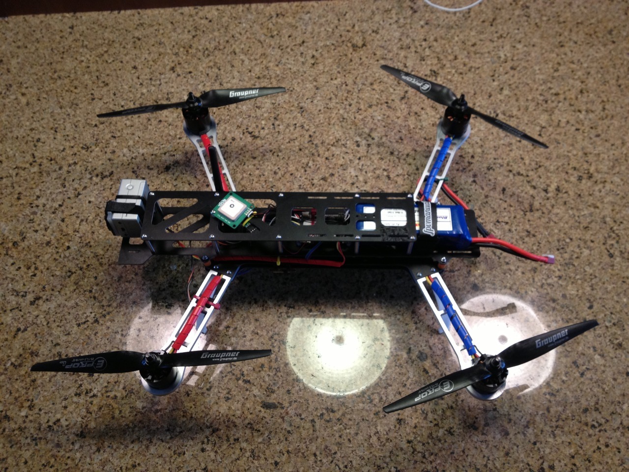
QAV500 frame
APM 2.5
SunnySky 2814-10 motors
Hobbymate 40A ESCs
Graupner E-Props 10x5
I have had a hard time getting this thing to play nice, and last night while reading more about ESC timing I realized that may have been my problem. I was having occasional motor spurts, and sometimes one or two motors wouldn't spin up initially, they would pulse and behave strangely. Early this morning I set the timing on the ESCs to low, and unsurprisingly it fixed the issues I was having.
I did a full config reset running 2.8.1, with motor size set for medium (0.110). Flight is a LOT more stable than it has ever been, and had a slight breeze too. All is left for me is to get more flight time, and practice, practice, practice!
Posted by Scott Berfield on November 13, 2012 at 10:00am
I wasn't sure what would be involved in getting a simple gimbal (in my case, just a tilt platform really) hooked up and working, but it was dead easy.
My wife recently made me a present of a GoPro Hero 2 and a tilt-mount.
This is a cheap little thing, but it fits the frame I have and it comes with the servo, and it was a gift - so you can't complain.
Took a look at the ArduCopter docs and was a touch intimidated, but as it turns out, it is really easy to get working. Once it was on the frame (took a little sanding and force), all I did was plug the servo into output 11 on the APM2.
If I had something that did roll as well as pitch, I would have plugged the roll servo into output 10 as well.
Where it gets really nice is that the Mission Planer has direct setting support for the gimbal now (as opposed ot what the docs say). I went to Mission Planner->Configuration->Camera Gimbal (duh).
On this screen, you can enable Tilt, Roll, and Pan individually, and can choose which channels to use for each. In my case, I enabled only Pitch, and set it to use "RC11" - this naming convention is a little confusing since RC indicates Radio, but it really is just the output pin number. I left the defaults for the limits. I chose Input channel "RC6" - which actually is a radio input channel.
I have channel 6 on my TX set to a pot for use in tuning, so I chose to use it here. Note - to use Channel 6 for the gimbal, you will want to make sure it is set to CH6_NONE in the ArdiCopter Config screen.
So in theory, channel 6 should set the angle of the mount and then the APM will maintain that angle to counter the pitch of the quad.
As soon as I picked up the quad, the gimbal worked. I could set the angle with the pot and it compensated for pitch as I tipped the quad back and forth. If only everything was this easy.
Once it stops raining in March next year, maybe I'll get to fly it.
On 14.8 Volts its pushing almost 500 Grams, not so bad thrust mapping is as follows.
100 Grams 1.9 A 27.6 Watts 156 Grams 3.0 A 42.9 Watts 197 Grams 3.9 A 55.1 Watts 257 Grams 5.5 A 76.0 Watts 296 Grams 6.7 A 90.9 Watts 340 Grams 7.9 A 105.5 Watts 432 Grams 10.7 A 138.1 Watts 492 Grams 12.5 A 155.7 Watts The data in a spread sheet The tests were run on two 7.4V 1300mAh Turnigy 20C Lipo's in series, I figure the motor will survive full throttle bursts on 4C and its 10 Amps short of the max, 100 Watts below its spec. Its surprising as the same motor with a 8 X 6 prop pulled 23.3 Amps on a 3C yielding 520 Grams of thrust at 232.3 Watts.
Weighs around 150 grams.
Need a plane for it should be pretty ugly with such a big fan
Thust 500 Grams
EDF & Motor 150 Grams
Battery 178 Grams
If the air frame can be built in 172 grams it will have an thrust to mass ratio of 1:1 pretty ambitious
A mass of 500 or 750 grams give a wing loading's of 13 oz/ft² and 19 oz/ft² respectively Wing area 1.3855 ft² Dihedral 5º Kf2 A symmetric trapezoidal wings and tail plane My Xbee based controller with appropriate RX software for the Jet
I will probably let the top stick out above the fuselage structure as its really a pusher prop in a tube. The jet location gives a neutral balance as is with out the tail and elevator or any servos.
If I sling the battery underneath I should have plenty of options for trimming the centre of gravity, as well as keeping it low compared to the motor which is mounted higher than the above example.
The wings are braced with bamboo skewers cheap as. I will chamfer the top leading edges as that's what most people seem to do.
I am advised that the elevators will need lots of authority so I will fashion quite large ones :)
Not sure there is anything to gain from having any sort of thrust tube yet, will test some ideas on the scales, and do some more reading. My intuition says keep the back low as possible behind the jet only the tail fin in the air flow and brace the structure from beneath. The 5º of dihedral gives some longitudinal stiffness so another V section in Coroplast running the entire length should do the job I think.
Posted by Jeff Barton on November 12, 2012 at 11:32am
Being involved in UAV research, I've been a member and a great admirer of this community for a number of years. An article I wrote (Fundamentals of Small Unmanned Aircraft Flight) has recently been published in my organization's Technical Digest and is freely available. I am hoping that members of the DIY UAV community might benefit from this effort.
The article covers flight control methods as well as UAV state estimation methods (i.e. fusing sensors to estimate position and attitude). Flight control algorithms are treated very generally, basically just describing simple PID control for different flight modes and channels. For state estimation, the article covers Kalman Filter-based approaches as well as the Mahoney/Premerlani/Bizard "DCM" method that many in this community are familiar with. (In the article, I refer to the "DCM" method as the AHRS Feedback Controller method, as it can also be described using quaternions or euler angles.)
Although the focus of the article is small fixed-wing UAVs, many of the methodologies described can be (and are) applied to other types and sizes of UAVs. The flight control and state estimation methods described are not specific to any particular UAV, but I will admit that I leveraged resources from the open-source UAV community. The article is freely available at the following link:
As a companion to the article, I also put together some heavily-commented MATLAB routines (called SUAS Code) implementing both the Kalman Filter and the "DCM" Feedback Controller state estimation methods. (For the really interested user, the code shows how to implement the "DCM" Feedback Controller method using either Euler angles, quaternions, or Direction Cosine Matrices.) A link to the code can be accessed through the MATLAB Central Link Exchange:
(The Link Exchange provides a link to the actual SUAS Code website. Please forgive me that this a "link to a link", but the MATLAB Link Exchange counts "clicks", giving me feedback as to whether anyone is finding it useful. Also, please be forewarned that you will have to OK an End-User-License-Agreement before downloading the code. It is intended that the code be freely available for academic, personal education, and research purposes. The EULA really just restricts commercial efforts, so hopefully no one in this community will find it too distasteful.)
Again, I am hoping that the paper and code are of benefit to this community.
There are a lot of new properties. You can search servos: by type (digital/analog), or you can choose torque and speed (4.8V, 6V, etc), or gears (metal, plastic):
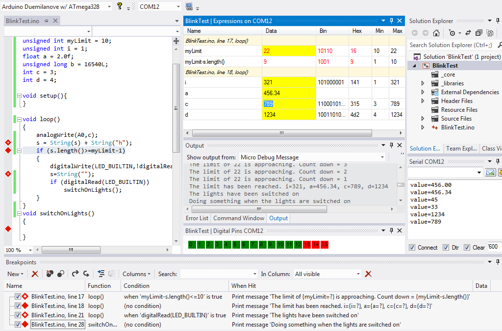
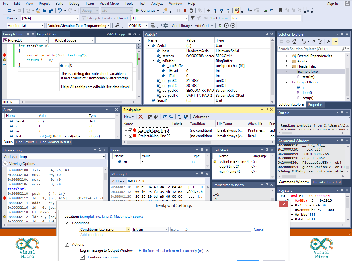
In May 2012 a unique serial debugger for Arduino was released in beta and has recently been updated to include the ability to change the values of variables while an Arduino is running.
In the image above you can see the entire code of a very crude (rubbish) Arduino program that is running a debugging session. You can see that the trace messages and variable values are different to those defined within the compiled program.
Approximately 300 people have joined the beta program. Feed back has been really great.
The debugger integrates seamlessly into the Visual Studio IDE providing conditional breakpoint, trace and expression watch features. Unlike a conventional debugger, the Arduino is not required to break (pause) to enable variable values to be altered (optional).
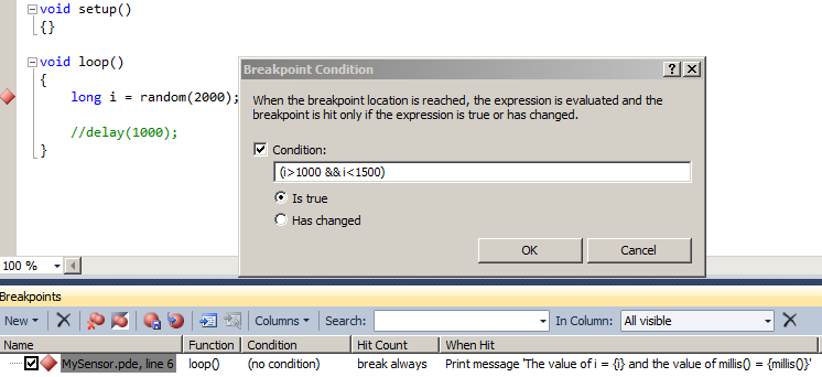
We can use any available Arduino code to conditionally apply breakpoints.
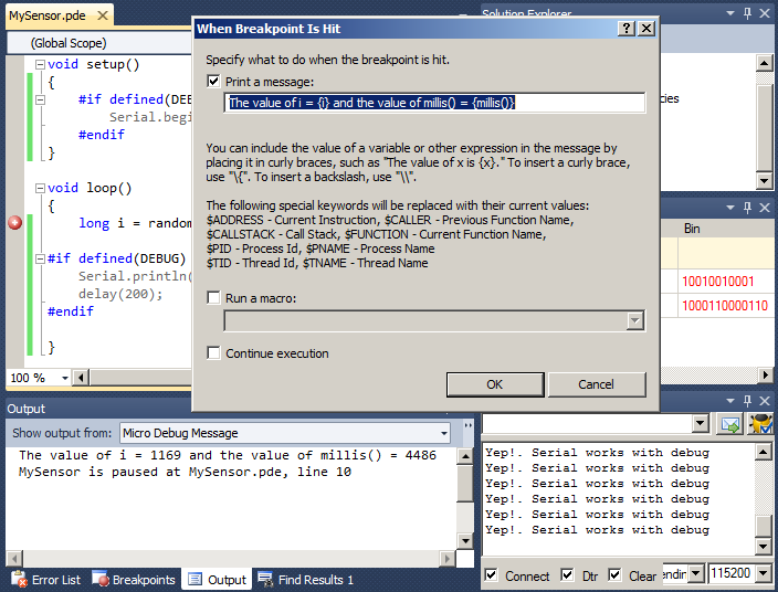
Complex or simple debug messages can be generated without the need to include the text of the messages in the final Arduino program. For most users this prevents the programs from becoming "bloated" with text/debug messages
APM FastSerial is fully supported. Debug using xbee is also supported but you should not fly a debug version without first becoming very familiar with how the debugger works. (If you are unsure then talk it over with us in the Forum). The image below shows a running apm debug session that is sharing the main serial port with the apm code. This is optional, we can share or use any arduino serial port (in most cases) or use other Arduino technologies such as SoftwareSerial.
The Arduino debugger is currently being distributed for free to anyone who would like to join the beta program. You can join the program by registering for the Visual Micro forum and including a request for the debug tool.
If you don't have a copy of Visual Studio Professional this article explains how to get a 3 year licence for free.
If you do use the debugger for an apm project (or with an apm example) then you will find a few tips for configuring an apm debug session here
The debugger is an upgrade to the free Arduino plugin for Microsoft Visual Studio Professional. Further reading, small wiki and a YouTube example can be found at visualmicro.com
The debugger optionally supports open source visualizations allowing us to create graphical controls that represent the various sensors of our Arduino projects
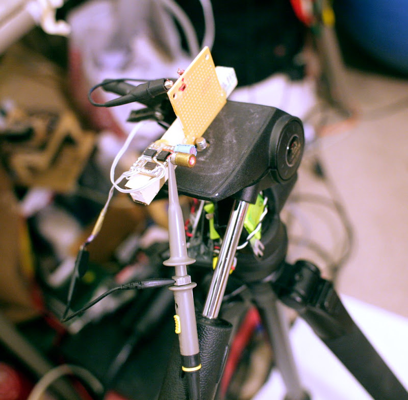
So ya wanna measure distance with 4 cheap radios & a cheap SRAM to measure propagation delay. Before investing in a full system, let's try it with a laser reflection & a Rigol.
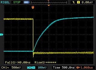
A laser diode is attached directly to a microcontroller pin via the shortest path possible. It'll get 3.3V at 50% duty cycle, so it won't burn out while still delivering useful brightness.
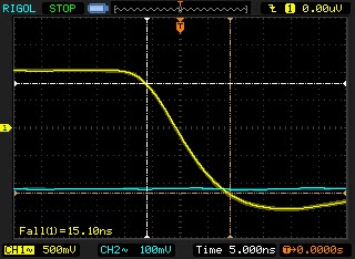
The laser rise time is given by the fall time on the cathode, which is extremely short. There's no way to measure how long it takes to light up, in this apartment.
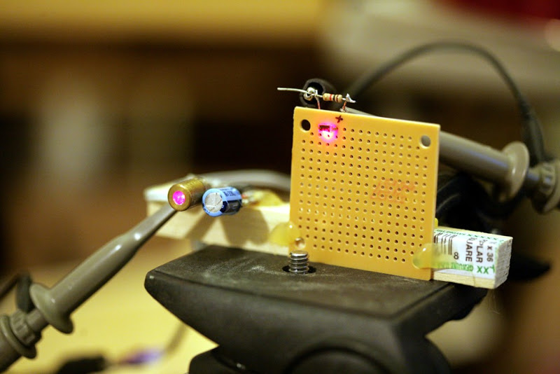
Next, we have a photodiode receiving reflected laser light from various distances.
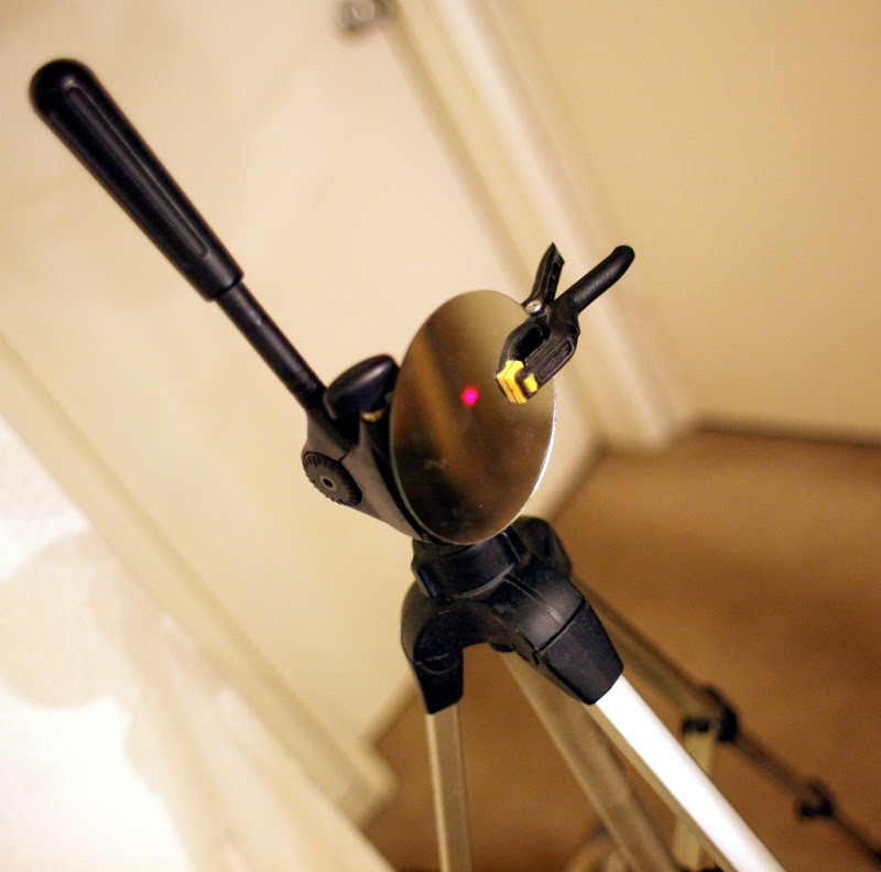
A very carefully, painfully aligned mirror reflects the laser. Should have used the heavier tripod for this.
With the mirror 1ft away, the Rigol now becomes the Rigol of despair, as the rise time of the photodiode is nowhere close enough to the rise time of the laser to see a delay on the screen.
What if you take the 1/2 way points of the 2 rises? That would get it to maybe 100ns, a distance of 30 meters.
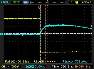
With the laser moved 15ft away, now the rise time of the photodiode is 4 times longer than before. It has too much capacitance, causing the half way point to be more correlated with signal strength than propagation delay.
Maybe a very low resistance pulling down the photodiode & a very high amplification would get rid of enough capacitance.
The mighty capacitance fighting resistor did get the rise time down to a more useful range at 15ft, but still very erratic. There still might be useful data with extreme averaging & the higher quality amplifier in a radio.
At 1ft, there's no obvious change in propagation delay with the noise.
A cheap radio would have automatic gain control & might have less capacitance, but the problems of longer rise time with a smaller signal & erratic half way point in the waveform would probably still be too great.
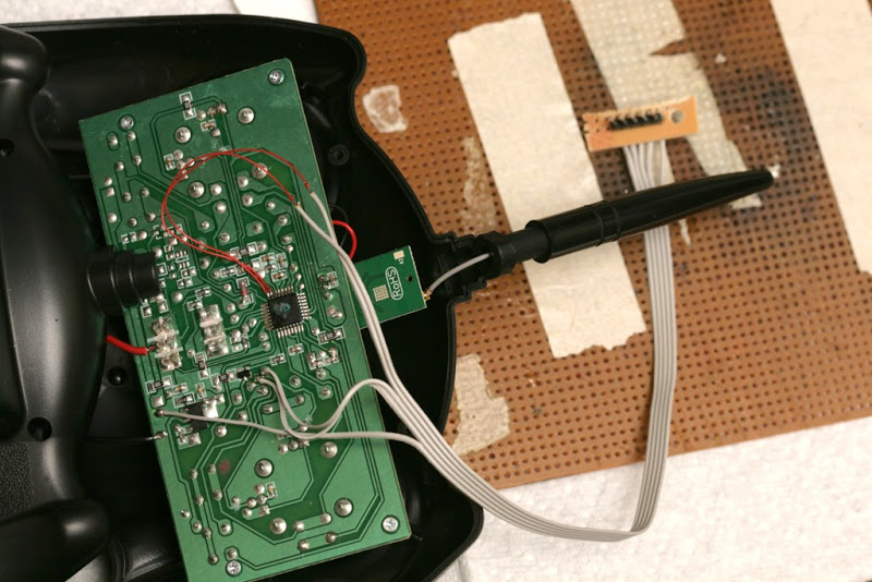
Another idea was to hack a laser tape measure to use a radio for part of the signal propagation. The same problems of capacitance & erratic rise time would apply.
The kind of components it would take to measure propagation delay of RF are going to be out of reach for a reasonable cost. You'd think someone would invent a local area GPS system, which used a different frequency, but used the same components to have a cheap GPS system in a room.
Over the years, the ability to detect a 1/115200 second time difference with a simple chip radio has led to the idea of measuring distance with low cost components. A pair of radios operating on different frequencies & hard wired so 1 directly transmitted the voltage received by the other could theoretically allow the propagation time of a voltage change to & from the aircraft to be measured. It would use a bank of staggered comparators, all timed by a slower clock, to detect very small differences in time.
10 staggered comparators timed at 100Mhz resolution would have 30cm accuracy. Averaging hundreds of samples might get it down to 3cm. It really depends on how noisy the signal is. Rough knowledge of RF communication says the lower the bandwidth, the less precisely the arrival time of a signal should be known. If it has 256kbit of bandwidth, the arrival time should only be known to 1/256000 seconds. But GPS has only 1megabit of bandwidth, so that shouldn't be a problem.
The Rigol & a set of 4 radios could do a simple proof of concept, up to 3 meter accuracy.
Anyways, the schedule is now to convert 1 new aircraft to autopilot every month, combined with several days of formalities required to run a business: meetings & traveling. It's extremely ambitious & doesn't leave any time for experimenting.
Posted by Chris Anderson on November 11, 2012 at 10:04pm
I mentioned a few weeks ago that Stephen Wolfram (Mathematica genius) and his 13-year-old son Christopher presented after us at Maker Faire NYC this year, and Christopher did a very impressive AR.Drone demo (with even more impressive on-stage debugging). Now Stephen hasposted with more info about that:
Christopher has been an avid Mathematica user for years now. And he likes hooking Mathematica up to interesting devices—with two recent favorites being Arduino boards and quadricopter drones.
And so it was that last Sunday I walked onto a stage with him in front of a standing-room-only crowd of a little over 300 people, carrying a quadricopter. (I wasn’t trusted with the Arduino board.)
Christopher had told me that I shouldn’t talk too long—and that then I should hand over to him. He’d been working on his demo the night before, and earlier that morning. I suggested he should practice what he was going to say, but he’d have none of that. Instead, up to the last minute, he spent his time cleaning up code for the demo.
I must have given thousands of talks in my life, but the whole situation made me quite nervous. Would the Arduino board work? Would the quadricopter fly? What would Christopher do if it didn’t?
I don’t think my talk was particularly good. But then Christopher bounced onto the stage, and soon was typing raw Mathematica code in front of everyone—with me now safely off on the side (where I snapped this picture):
His demo was pretty neat. He had a potentiometer hooked up on the Arduino board. And he’d set it up so that all he had to do was type a command intoMathematica to get its value:
Then it was Dynamic[ArduinoAnalogRead[0]], and Mathematica is dynamically displaying the value in real time as he adjusted the potentiometer.
Then he makes it into a gauge (er, that’s actually from a future version ofMathematica, but Christopher is a keen user of internal development builds):
And then he says he’s going to make a dynamic plot of it. And pretty soon he’s typing the Mathematica program, confidently presses Shift-Return—and it actually works:
Then he’s on to using an ultrasound sensor, and having it produce musical notes based on distance.
And then he’s on to the quadricopter. He’d been going back and forth with someone at our company for a few days before, trying to get the kinks out of the interaction with the quadricopter‘s API. I had seen the quadricopter fly that morning, but I knew Christopher had changed the code quite a bit since then.
His plan was to have a single line of Mathematica code that would make the quadricopter fly a specified 3D path. He had a list of points for a square, entered the line of code, and pressed Shift-Return, and… nothing happened!
I guess Christopher has debugged quite a lot of code in his 13 years. And now he set about doing it in front of the audience. A missing function definition. A missing command to connect to the device. He was finding quite a few things. And I was getting ready to call out that he should just give up.
But then… the sound of quadricopter blades, and up the quadricopter goes… flying its loop on the stage, and landing.
It had actually worked! It was pretty neat, being able to just type one line of code into Mathematica, and then having some physical object fly around in the pattern one had specified:
After another flight, the audience had questions. One person asked if the quadricopter could respond to its environment. Which set Christopher off on some more “spectator programming”. And actually, it took him only a line of code to get the real-time video from the flying quadricopter, and feed it through simple Mathematica image processing:
I was pretty impressed that all this worked (here is the full video). And, yes, Christopher was clearly right that his topics were very relevant to Maker Faire. In fact, it seemed like Arduino and quadricopters were two of the three main technical themes of the show. The third was 3D printing.
Ok, so Big Footing is not exactly "Main Stream", but IMO, this is a great example of how we can enjoy our hobby while helping others explore theirs. Unfortunately, there's not a lot of details on the drone or UAS Operations but it's a positive example none the less. I live in Northern California, and want to take my drones on a BFRO expedition...
This one is called, er, the "Bad Ass HoverWASP RC Quadcopter". It's created by a team who call themselves "Two Silicon Valley Engineers" but seem to actually live in Reno, Nevada ;-) They want $1050 for the GPS version (for hold and RTL only) of their quad, although it does come with a GoPro camera and some kind of RC gear (looks like the $59 Turnigy). Doesn't appear to be open source. At the moment, they have six backers.
Our prototype is a quadcopter that took over seven months to develop the proprietary algorithm for stability. This drone has four propellers that requires a special software code to maintain stability while flying. This is especially important if you do any videotaping to avoid a “jello” effect.
We will have a "ready to fly" out of the box quadcopter. Most airplane and helicopter drones all require a technical assembly process that can be difficult and tedious such as programming your radio transmitter and your flight controller along with wiring and soldering. Our “ready to fly” out of the box drone is so simple that you can let your child fly it.
We have partnered with a manufacturer to build all the parts to our quadcopter and we will assemble the final product in the United States. But to manufacture the parts and assemble it we need your help. The crowd funding from Kickstarter Backers will allow us to go from beta-prototype into final production.
Puzzlebox Orbit features a unique spherical design that protects helicopter blades from unintended impact with objects such as walls and ceilings, while lending a pleasantly technical aesthetic. Despite remote control helicopters in general having earned a reputation for being fragile we have been extremely pleased with the build quality and resilience of our samples. They have survived several falls and collisions over the course of development and testing without noticeable damage.
We offer two models, the first designed to be used with mobile devices such as tablets and smartphones. A NeuroSky MindWave Mobile EEG headset is required to communicate with the device over Bluetooth. Our software then extracts and visualizes your brainwaves in realtime. Command signals are issued to the Puzzlebox Orbit via an infrared adapter connected to the audio port (for compatibility with Apple's iOS).
Puzzlebox Pyramid (Prototype)
Puzzlebox Pyramid is supplied with our second, self-contained model. The Pyramid acts as a home base and remote control unit for the Orbit. It features a custom-designed, programmable micro-controller compatible with popular boards from Arduino. Twelve multi-colored LED lights are arranged according to clock positions on the face of the Pyramid and are used to indicate current levels of concentration, mental relaxation, and EEG signal quality. The lights can be customized to display different colors and patterns with distinct meanings according to preference. Lining the rim are several infrared LEDs that operate the helicopter and with software programming are capable of controlling additional IR toys and devices including televisions.
With either edition the user can select a "flight path" for the helicopter (such as "hover in place" or "fly across the room") to be carried out whenever a targetted personal mental state is detected and maintained. Third-party developers are able and encouraged to contribute new features and modes of flight control.
Puzzlebox Orbit relies on EEG hardware from NeuroSky to produce measurements of attention and meditation. Leveraging their hardware plus our proven track record with BCI has yielded a much faster and smoother time to market, empowering us to focus on building the best possible product and software. We offer rewards to backers both with and without pre-packaged headsets included.
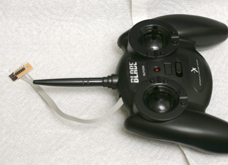
This first part only happens to some..... so skip it if it does not apply
. My first problem with this started when downloading it. it apparently didn't recognize the .inf driver file so it associated it with notepad and gave it a .txt extension. of course you normally cant see it because know extensions are hidden. anyways,, after you fix that that, how to get it to run? the old tricks dont work, and I want a permanent one...so I read this:
Now. The steps to install a unsigned driver on windows 8 is as follows.
1. From windows 8 desktop, put the mouse in the corner so you can hit settings, then hit Change PC Settings at the very bottom again and it will take you to the advanced setup screen, then choose General –> Under “Advanced Startup” –> Restart now.
Now the system will restart and might take some minutes to show up the boot menu. Wait for It patiently.
After some time you will be prompted with a menu with following options.
1. Continue
2. Troubleshoot
3. Turn off
Choose Troubleshoot
Then the following menu appears.
Refresh your PC Reset your PC Advanced Options Choose Advanced Options
Then the following menu appears
System Restore System Image Recovery Automatic Repair Command Prompt Windows Startup settings Choose Windows Startup Settings, then Click Restart.
Now the computer will restart and the boot menu appears. Choose “Disable Driver signature Enforcement” from the menu. Now windows will start and you can do the installation of the driver that is not signed. Smile.
This seems to be a permanent fix, unlike the F8 fix in windows 7.


![data = {}; Dynamic[rawdata = ArduinoAnalogRead[0]; AppendTo[data, rawdata]; ListLinePlot[data,Filling -> Axis, ImageSize -> 500], UpdateInterval -> 0]](http://blog.stephenwolfram.com/data/uploads/2012/10/In-3.png "data = {}; Dynamic[rawdata = ArduinoAnalogRead[0]; AppendTo[data, rawdata]; ListLinePlot[data,Filling -> Axis, ImageSize -> 500], UpdateInterval -> 0]")


 Puzzlebox Pyramid (Prototype)