All Posts (11086)

Sort by

RTK GPS based landing: test results

3689709289?profile=original

Lately, a lot of companies have commercialized their own RTK GPS receiver. On this blog I will provide information about accurate landings based on an AsteRX-m UAS receiver which works on L1 and L2 frequency.

I’ve tested landings with an f450 DJI frame with the following setup:

  • 11 inch props
  • 5000 mAh battery
  • Total weight: 2kg
  • Autopilot: Pixhawk
  • GCS: Mission Planner
  • RTK GPS Asterx-m UAS
  • RTK correction data: RTCM3
  • GPS Antenna: AA_ANT_NM_DF_L (AT1675-504)

Because I also wanted to analyze if the ground effect has influence on the accuracy from the landing I performed 50 landings on a solid platform and 50 landings on a wire frame (shown in the picture below). Before the test I expected that the accuracy on a wire frame would be better.

To improve the accuracy from the landings I tuned the following parameters from the Extended Kalman Filter (we want to rely more on the RTK GPS because it is much more accurate than the standard GPS module) :

  • EKF_POSNE_NOISE: 0,1
  • EKF_VELNE_NOISE: 0,05
  • EKF_ALT_SOURCE: 2 (you can use the RTK GPS in combination with the barometer to measure the altitude)

The following mission script was used to realize the autonomous landings:

1)      Take off from platform to 5m altitude (solid/wire frame)

2)      Fly to waypoint several meters from the platform

3)      Return to waypoint 5m above landing platform

4)      Delay for 2s in an acceptance radius from 10cm

5)      Land on the platform 

Landing results:

3689709227?profile=original

The accuracy of all 50 landings was better than 20cm (wind speed was low 10 km/h so there were no outliers). The standard deviation is 4,12cm and the mean accuracy 7,43 cm.

3689709241?profile=original

Almost all landings had an accuracy of at least 20cm. I had one outlier of 24 cm because there was a wind burst. The mean wind speed during the test was 20 km/h. The standard deviation is 4,79 cm and the mean accuracy 8,08 cm. The accuracy is less than the accuracy on a solid frame because there was more wind.

Conclusion:

  • The ground effect didn’t had influence on the accuracy from the landings (probably because the weight of our drone is quite large, I expect more influence on a frame with lower weight)
  • Improvement of the landing results when there is more wind can be realized by aligning the vehicle at an altitude of 1m and realizing a fast descent when the vehicle is on the xy position from the landing spot.
  • An RTK GPS shows its potential to land on a base station in open areas or on top of buildings. In more closed environments it takes longer to have RTK fix.

Further improvements:

  • What is the accuracy from the landing when there is a lot of wind?
  • Is the RTK GPS also accurate at high speeds?
  • Is this accuracy also possible with the cheaper L1 RTK GPS? (Let me know if you are interested in this)

An example from an RTK based mission:

https://www.youtube.com/watch?v=m9KKw6Y5jCs

More info: stijn.dbr@gmail.com (let me know if you want access to the raw data and logs from the test)

Read more…
3D Robotics

3689709089?profile=originalIt's been almost a decade since I launched DIY Drones (March 2007) and we've both grown hugely as a community and an industry in the intervening years. Drones work great, they're cheap and widely available, and both the the Dronecode and ArduPilot development communities that got their start here are doing amazing work to advance the technology, which is now at pro/aerospace level. So what's left to DIY? 

How about autonomous cars? We actually got started with GPS-guided autonomous cars seven years ago with the ArduRover project, which is now the standard for outdoor rovers such as those that compete in the Sparkfun Autonomous Vehicle Competition. But as the human-scale self-driving car industry takes off, more sophisticated computer vision and AI technology is the new frontier.  There are scores of companies doing this, from Google and Tesla to Uber, GM, Ford, BWM and virtually all the other big car firms. But what about DIY? 

Sounds like time for a new site/community! Thus DIY Robocars, which I've just launched in beta as a companion to this site. Right now it's just a blog, but I'll turn on the community forum elements in a week or two once I've got the core contributors in place. This one is based on the WordPress/bbPress stack, which should be more robust than the Ning platform that DIY Drones is based on. If it works well, we may port DIY Drones to this, too.

3689709273?profile=original

As you can see, I still don't have a good logo. Any ideas?

Read more…

3689709154?profile=original

An architect studying at the Institute for Advanced Architecture of Catalonia in Barcelona, Spain, has today released details of a design for the drone transportation hub of the future.  This project is unique for two reasons - the first is that the design repurposes a disused bullfighting ring from the early 1900s, and the second is that he has released the design and associated models to the community for comment, modification and sharing as a way to stimulate discussion about the role that drones will play in our lives.


“I wanted to make people feel part of the conversation...drones are such an incredible thing that we  sometimes feel afraid of, or don’t understand, and yet these days they are well within our reach.”

-       Frederick Ajjoub, Architect


Teaming up with Rowland Marshall, an Australian drone consultant based in Paris, Frederick Ajjoub took great pains to infuse the function of the future whilst preserving the existing structure.


“The metier of the architect is the continual pursuit of a delicate balance between design and function; history and story; vision and realisation.  This project is the very thesis of such a challenge, fusing together the future of flight and robots with the earthy, sanguine world of the bullfighter in a manner that elicits new life whilst respecting the proud history of bull fighters.”


Frederick is calling for comments and feedback from the community, and has even released the design files as a 3D model for discussion.


Details of the project can be found in articles here and here, and the 3D files can be found here. 


https://www.linkedin.com/pulse/la-monumental-re-imagining-1900s-bullfighting-ring-drone-ajjoub

https://www.linkedin.com/pulse/what-number-42-means-me-how-turn-1900s-bullfighting-ring-marshall

https://3dwarehouse.sketchup.com/model.html?id=2e60e5a6-b6f2-41d3-a5fa-3c28412a3831


Frederick Ajjoub, Architect

‪+34 644 892 459

frederickajjoubarch@gmail.com


Rowland Marshall, Drone Consultant

+33 7 82 45 87 05

rowland.dronearena@gmail.com

Read more…

Second generation of thermal imaging camera WIRIS

3689708517?profile=original

In the coming days it will be one year from the date the company Workswell launched a revolutionary thermal imaging camera for drones Workswell WIRIS. And today after one year.... we would like to introduce you a second generation of Workswell WIRIS with a lot of new features.


Workswell WIRIS 2nd gen is currently the most state-of-the-art thermal imaging system designed for commercial unmanned aerial vehicles, so called drones. It is a compact system that combines a thermal camera, a digital camera (set to a visible spectrum), and a processor unit that has possibility to record radiometric data with a digital HDMI output, all in one case.


New features

Very listened to our customers and based on their initiative we are coming after a year with many improvements over the original system. So although cover facilities remains virtually the same we came up with a second generation of Workswell WIRIS with a lot of new functions and features:

  • SBus
  • CAN bus 
  • high temperature filter, now you can measure up to 1500 °C 
  • faster 10 Hz GPS with jack connector
  • new TIFF format for images
  • device control or video streaming via TCP/IP 
  • real time clock is now more accurate
  • digital outputs for autopilot confirmation and GPS synchronisation
  • integrated power supply 5 V for RC transmitters
  • 4 mouting holes for easier mounting

Due to this, currently 7 digital PWM inputs are now available (the 8th digital input is used for SBus).

Lets see some pictures

3689708464?profile=original

Frontside with high temperature filter - with high temperature filter you can measure up to 1500 °C!

3689708382?profile=original

WIRIS's backside - there are a few changes on the back side. You can see connector for Sbus, jack GPS connector (for 10 Hz GPS) and on request an optional connector for CAN Bus.

More informations 

More informations are avaible on our website.

If you are interested in that product, we have more than 30 resellers and partners worldwide.

Read more…

Andruav 12,193 km RC Car Demo

This could be a record breaking. The above video shows a demo with Andruav to actually control a RC Car from LA in Cairo using Andruav, the distance is 12,193km 7576 miles between the driver in LA & the car in Cairo.

The demo was done in my home, and the car is pretty fast, so a caution was required when controlling it to avoid fast jumps.


The configuration is like described in the below image.

3689708360?profile=original

LA Configuration

Andruav-GCS running on a tablet, the tablet shares wifi with a laptop that runs mission planner, the mission planner is connected using TCP/IP to Andruav-GCS that acts as a telemetry. A Joystick is connected to Mission Planner for control.


The Tablet itself is running opens FPV screen using Andruav, it display what is captured by the RC Car mobile that is mounted on it.

Cairo Configuration

There were two separate Andruav there.

1- Andruav-GCS on WebClient, this is what we see on the large monitor, it shows Mario Location & it connects to Andruav-Drone “RC Car” same as the GCS in LA and display the very same video that Mario see in LA through Andruav-GCS on tablet. One-to-Many video streaming is one of the nice features in Andruav.

3689708408?profile=original

3689708337?profile=original

2- Andruav-Drone “RC Car”, the car has an APM board and a bluetooth module. A mobile is mounted on the car an connects to APM via bluetooth. It runs Andruav-Drone.

3689708436?profile=original

The other video from Cairo that shows the car on the other side is this one:

At last I want to thank Mr. Mario for his video & support.

Read more…

I read this on the newspaper today and i think this is one interesting genius way to land a UAV (the bird style). 

Researchers combined a morphing wing drone and machine learning algorithms to create a system that lets the machine perform perched landings on the ground. The fixed wing aircraft also has the ability to land in small or confine places, which deliver aid in disasters

These researchers from the University of Bristol and BMT Defence Services did a great job :-D well done!

The article you can read it here http://www.dailymail.co.uk/sciencetech/article-4115344/The-end-runways-Watch-incredible-perching-plane-land-like-bird.html


Read more…
Moderator

swiftboys-696x785.jpg

Swift Navigation, the San Francisco-based startup building centimeter-accurate GPS technology that will power a world of autonomous vehicles, is proud to announce that two of its co-founders, Fergus Noble (29) and Colin Beighley (28), have been honoured in the 2017 Forbes 30 Under 30 Consumer Technology list. The list, which honours 30 young leaders in each of 20 different industries, is “the world’s greatest roll call of young entrepreneurs and game-changers,” according to Forbes. Acceptance into its consumer tech list is less than 4%, making it more competitive than getting into elite universities like Stanford or Harvard.

Full story

Jordi made that the same year as the Lily folks...

http://www.forbes.com/sites/alexknapp/2015/01/05/30-under-30-reinventing-manufacturing-in-a-greener-tech-savvier-world/#29cd5dbe6e61

Read more…
3D Robotics

NASA simulates Phantom airflow

From NASA:

For decades, NASA has used computer models to simulate the flow of air around aircraft in order to test designs and improve the performance of next-generation vehicles.

At NASA’s Ames Research Center in California’s Silicon Valley, researchers recently used this technique to explore the aerodynamics of a popular example of a small, battery-powered drone, a modified DJI Phantom 3 quadcopter.

The Phantom relies on four whirring rotors to generate enough thrust to lift it and any payload it’s carrying off the ground. Simulations revealed the complex motions of air due to interactions between the vehicle’s rotors and X-shaped frame during flight.

As an experiment, researchers added four more rotors to the vehicle to study the effect on the quadcopter’s performance. This configuration produced a nearly twofold increase in the amount of thrust.

The findings offer new insights into the design of autonomous, heavy-lift, multirotor vehicles for uses such as cargo transportation.

This research was presented at the 2017 American Institute of Aeronautics and Astronautics SciTech Forum in Grapevine, Texas, by Seokkwan Yoon of the NASA Advanced Supercomputing Division at Ames.

Read more…

3689708497?profile=original

Agribotix has partnered with senseFly to offer a new combined solution for professional agriculture users. This solution combines the eBee SQ drone, Sequoia sensor and Agribotix FarmLens data processing technologies to make collecting and analyzing aerial agricultural data easier than ever.  The eBee fixed-wing drone allows several times more coverage, per flight, than is possible with most quadcopter solutions.   The Parrot Sequoia sensor, features four multispectral sensors plus RGB, so a single flight produces RGB (visible) and near infrared results.


3689708936?profile=originalFarmLens cloud processing gives users the unique ability to perform the full crop scouting workflow: fly large areas efficiently, reliably upload the data and rapidly produce field maps highlighting problem areas, mobile friendly presentation to aid in-field ground truthing and capture of photos and notes, and printed and on line reports that provide the client with detailed findings and recommendations about their fields. FarmLens users gain valuable insights about crop conditions without having to become experts in data processing. 

Read more…

PC tablet based sUAS GCS

3689708109?profile=original

Here  is another take on our wearable control tray format, this time with an embedded Win tablet PC that does it all for you. It has the same footprint as our previous trays (e.g. http://diydrones.com/profiles/blogs/fold-up-gcs-with-android-telemetry), but this one has more of a Spartan practicality to it, really.

While this unit was prepared with three built-in RF modules for testing and prototyping purposes, the station framework also works with an external RF box, and in fact with a fully digital link, as well.

3689708030?profile=original
Just to be backward compatible with both combined and separate RC/modem solutions, or even a diversity A/V RX, we made room for a maximum of three RF modules inside, and three antennas on top of the controller for short-mid range applications up to a few kms, even without external modules. When using analogue A/V RXs, the video signal is fed through a frame grabber to the tablet with very little latency, so you have a choice of displaying the video downlink either full screen in FPV, or in a window/overlay in your favourite GCS sw when flying auto missions. When using a digital video downlink, you can either opt for the wired LAN port from your external RF box with IP video, or you can just install a ground WLAN bridge for the tablet Wifi inside.

Despite this unit having a PC inside, since most current Android ground station sw packages also support overlaying the direct downlink video on the GUI in various configurations, there's no reason why the very same design wouldn't work with an 8" Android tablet without any serious modifications.

3689707947?profile=original

The current IT core:
modified high nit and high contrast 8" PC tablet with either

Intel® Atom™ processor Z3740D/Z3775D
2GB DDR3L-RS, 64GB eMMS
1280x800 IPS display

or

Intel® Atom x5-Z8500
4GB LPDDR3, 64GB SSD
1920x1200 IPS display

3689708045?profile=original
Both original business tablets can sport a built-in HSPA+/LTE modem, but we favour an external USB dongle connected to the front of the tray, because you never know which service provider will have coverage at a particular rural area. Replacing the SIM card in a dongle or the entire USB modem itself is much easier than getting to the SIM slot of the tablet itself...

We have installed a modified OTG USB hub to allow charging the tablet's 20Wh built-in battery on the fly while still linking frame grabber, telemetry modem, 4G dongle, LAN module, etc. to the tablet hw. Depending on charge levels you can power both the tablet and the rest of the control tray hw from the 85Wh or 7500mAh of balanced and protected 3S lipos. This gives you a minimum of 5-8 hours battery endurance for the whole station.

3689708160?profile=original
Although this unit contains both an EzUHF LR RC module and an RFD900 modem for compatibility, we can install TBS Crossfire, DragonLink or ULRS for combined RC/TM modem to make it even simpler. Also, while there is a 5.8GHz ImmersionRC UNO AV RX in there right now, depending on your preferred hybrid band plan the AV can still be any of the usual 900MHz/1.2GHz/5.8GHz modules available.

The RC TX logic is our own miniature take on the open source 9x architecture, so you can choose your favourite firmware for both PPM and SBus systems. We are currently running a modified 12ch version of the fw with the EzUHF module, but a 16ch SBus setup is also possible with certain RF modules.

3689708123?profile=original
As a personal note, I'm not entirely happy with these separate add-on type labels on the controls, because the colour filled engraving looks way more elegant directly on the main CF board. However, this is an easy way of customising or rearranging the switch functions without having to recut the entire top CF board.

3689708220?profile=original
Of course, this belly box model still conforms to our favourite standard compact station format, so a Peli 1400 type enclosure fits it like a glove. We can pack it in the same box with a double field charger, a second telemetry station or with a huge separate compartment for an external RF box, cables, antennas and other accessories.
 

Read more…

3689708252?profile=original

With the increasing interest in the use of multi-rotor UAVs for long range applications such as pipeline inspection, large-area mapping, transporting packages or even people, the question arises: “how far can they fly?”.  

In this post I’ll present a theoretical approach, an experiment and a conclusion to answer this question. Let’s start with some basic theory that can be used for all flying things. The distance d that a UAV can cover, flying at a constant mass and velocity v is presented by:

3689708244?profile=original

With t the flight time calculated as the available energy in the battery divided by the total required electrical power:

3689708165?profile=originalAssuming the power required for propulsion is some orders of magnitude larger then power for payload or avionics, the total required electrical power can be calculated as the power required for propulsion divided by the overall efficiency of the propulsion system (losses in cables, ESC, motors, propellers, air).

3689708249?profile=original

For the same battery chemistry and manufacturing process, we can assume that the energy available from the battery linearly depends on its mass:3689708170?profile=original

For Li-Po batteries, a value of 180Wh/kg is possible or in SI units:

3689708175?profile=original

The mass of the battery is a fraction of the total mass of the UAV. For example a UAV with a total mass of 4kg, including 1kg of battery has a 25% battery fraction:

3689708304?profile=original

The theoretical power that is needed for propulsion is calculated as the flight speed multiplied by the drag:

3689708180?profile=original

For fixed-wing aircraft this formula makes sense but multi-rotors also consume propulsion power to create lift, right? The propellers create both lift AND propulsion. This is analog to an airplane which uses wings and a propulsion unit (propeller or jet) to create its lift and propulsion respectively. So just consider the propellers of a multi-rotor acting as a wing and a propulsion unit simultaneously.

We do not know the drag of the UAV and we cannot measure it. Why not? For a fixed wing aircraft you can put the aircraft in the wind tunnel and measure the drag with a force sensor with the propulsion unit producing zero thrust. Or we can measure the thrust of the propulsion unit in flight with a force cell. We can do this because the propulsion unit and the ‘lift unit’ (=wings) are separated systems. Because the propellers of a multi-rotor act both as wing and propulsion unit, we cannot simply remove them and measure the drag in a wind tunnel. This would be the same as measuring the drag of a fixed-wing aircraft without the wings. Because we cannot separate lift and thrust (= drag in regime flight), we continue with a generally accepted ratio in aviation: the maximum lift-to-drag ratio, also known as the aerodynamic efficiency or glide ratio. A glide ratio of 10 for example means, if you shut down the propulsion unit, that you can travel maximum 10 meters while descending 1 meter.

3689708274?profile=original

The glide ratio of a fixed-wing aircraft is easily measured this way and are in the order of 10 to 40. For helicopters, it can also be defined by gliding down in auto-rotation. Therefore the blades are given a negative pitch and they act like a wing of a glider, but then rotating. Typical ratios are around 4 or lower. Because we cannot change the pitch of the blades of multi-rotor propellers, it is not possible to determine the lift-to-drag ratio by gliding down in auto-rotation.

We’ll have to find a way to determine exact the lift-to-drag ratio for multi-rotors later on, but let’s assume for now we know the ratio and it is less than a full-size helicopter in auto-rotation (4) and more than a wingsuit (2.5).

3689708309?profile=original

We also know the lift, which is equal to the weight:

3689708185?profile=original

Rearranging former equations allows us to calculate the maximum range:

3689708279?profile=original

Since the propellers act as both wings and propulsion unit, it is also not possible to determine solely the efficiency of the propulsion unit. Therefore, we have to consider the two factors marked in yellow as one unknown value. We can make an educated guess however: the efficiency will always be <1 and the lift-to-drag ratio will be probably <4. Therefore, we can calculate the maximum range of a multi-rotor with 180Wh/kg batteries and 25% battery as:

3689708314?profile=original

The energy density of the battery and the fraction of the battery are easily measured and should be maximized to get the highest range.

We assumed that  

3689708191?profile=original

but we need a way to know this number for a multi-rotor. This number is a combination of aerodynamic and electric/mechanical efficiency of a multi-rotor and would be a good benchmark to validate the capability of a multi-rotor to cover large distances.

Doing some more math with former equations allows us to determine the highest value of this number by performing some test flights at different flight speeds (yay! No wind tunnel test or force cells required, only a speed and a power measurement!)

3689708324?profile=original

If we want to consider only the aerodynamic performance of the multi-rotor, including the propellers, we can define a ‘theoretical glide ratio’, which we cannot achieve because auto-rotation is not possible:

3689708196?profile=original

With P_mech the total mechanical power delivered to the propeller shafts during cruise flight. This can be measured or calculated if the efficiency of wires, ESC and motor is known for all possible operating points.

Now the big question: what is the theoretical glide ratio of a multi-rotor? During my PhD, I performed many test flights with different multi-rotors and here are the results for a popular setup:

3689708288?profile=originalThe best total flight efficiency of this setup was:

3689708329?profile=original

occurring at a total mass of 1.6 kg and a speed of 16.3 m/s. With a 25% battery fraction and 180Wh/kg batteries, this results in a range of about 20km.  Because I measured the efficiency of the motor and ESC in all possible operating regimes on a test bench, I was able to also compute the theoretical glide ratio:

3689708353?profile=original

So that is somewhere in between a flying squirrel and a wingsuit (not too good!).

Conclusion: The range of multi-rotor can be easily computed if you know the ‘flight efficiency’, which is a combination of the efficiency and aerodynamics of the ESCs, motors, propellers and the body/arms/wings. The best flight efficiency of a conventional quadcopter was calculated from flight data as 1.2 and the accompanying ‘theoretical glide ratio’ was 2.13. People working on VTOL hybrid solutions should be able to increase this number towards glide ratios of fixed-wings (> 6). However… battery fraction is of equal importance if you want to maximize your range.

Question: what is your flight efficiency and battery fraction? I’d love to see some comparison between multi-rotors, helicopters, fixed wings and hybrids!

If you like to learn more about the performance of multi-rotors for high speeds, long range, endurance, payload capacity, you want access to all the data on different vehicles or for more specific questions contact me on bart.theys@kuleuven.be

Read more…

3D printed tray for Graupner MZ-24

3689707900?profile=originalHi again, this is my custom designed tray for my Graupner MZ-24. My goal was to build a small tray that can be removed easy without any tools and small enough to be put next to my transmitter in my bag. I think I succeed... :)

Suggested print settings:

  • 0,2 mm layer height
  • 3 layers all around (top, bottom, perimeters)
  • 40% infill, 3D honeycomb

STL files for download are here.

Since the fixture element connects to the transmitters leg, accurate printing is a must without any print defects on the connecting surfaces (ie. bloobs, holes, etc.)!!! Good luck!

Regards, Adrian

3689707840?profile=original

3689707965?profile=original

3689707918?profile=original

Read more…

FA-18 Releases 103 Perdix Micro-Drones

Naval Air Systems Command, successfully demonstrated one of the world’s largest micro-drone swarms at China Lake, California. 

  • Propellers: 2.6 in    
  • Body: 6.5 in    
  • Wing span: 11.8 in    
  • Weight: 290 g    
  • Endurance: >20 min    
  • Air speed: >40‐60 kts 

Originally designed by MIT engineering students,the Perdix drone was modified for military use.  They are autonomous micro-drones capable of low altitude Intelligence Surveillance and Reconnaissance and other missions. From what I read, they can be launched from air, sea or ground.

a9678041-80-perdix.PNG


News Brief at https://www.youtube.com/dronemission

Read more…
3D Robotics

3689707997?profile=original

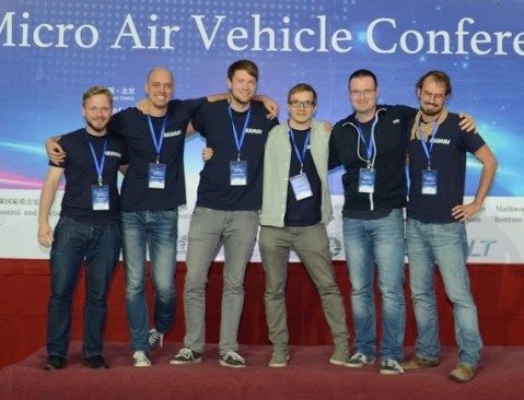
Congrats to the AKAMAV team for the victory and great writeup (via Hackaday)!

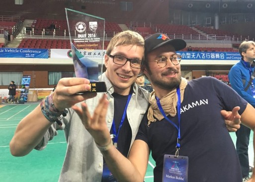
The AKAMAV is the proud winner of the IMAV 2016 Outdoor Challange. In this post we want to share the approaches, strategies and experiences we made in the past months.

INTRODUCTION

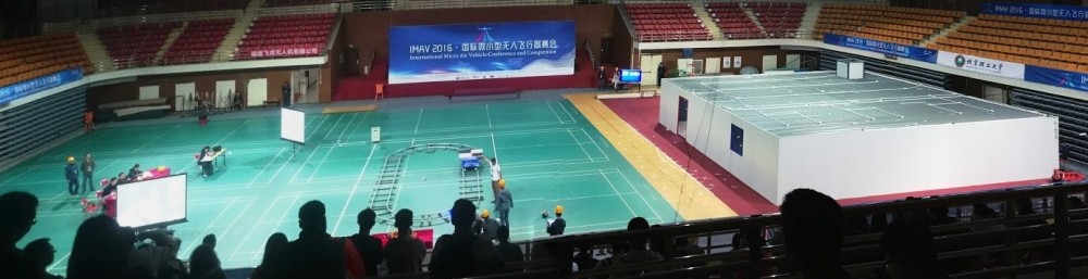
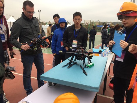
The IMAV (International Micro Air Vehicle Conference and Competition) is one of the biggest academic drone events these days. It’s hosted by a different university each year. 2016 was the first time it was hosted in China namely by the Beijing Institute of Technology. The amount of work and hospitality the organizing team put into this was one of a kind. Roughly 20 teams from all over the globe attended. If you share a remote interest in flying robots and don’t mind the occasional spectacular crash, this place was Disney Land on steroids with autonomous drones and Chinese noodles.

1.jpg

The competition was parted in an indoor and outdoor part. The goals of the missions were inspired by a hypothetical spill on an oil platform. To save the world from a horrendous hypothetical disaster, drones had to rush in and master the following missions:

OUTDOOR3

  1. takeoff from moving platform
  2. live mapping mission area
  3. precise delivery of a life buoy
  4. collecting and delivering of water sample
  5. landing on moving platform

INDOOR

  1. takeoff from moving platform4
  2. entering a building
  3. mapping the building
  4. picking up and releasing specific objects
  5. exiting the building
  6. landing on the platform

5The complete rule set and all related information can be found here. In a nutshell: Each mission was scored depending on the achived difficulty level (e.g. landing on the moving vs. landing on the standing platform), depending on how small the vehicle was (smaller = better), how autonomous the mission was performed (no human interaction = happy judges) and how many missions were done in a single flight. Two vehicles could operate at the same time. FPV or LOS flying wasn’t permitted outdoors.

APPROACH

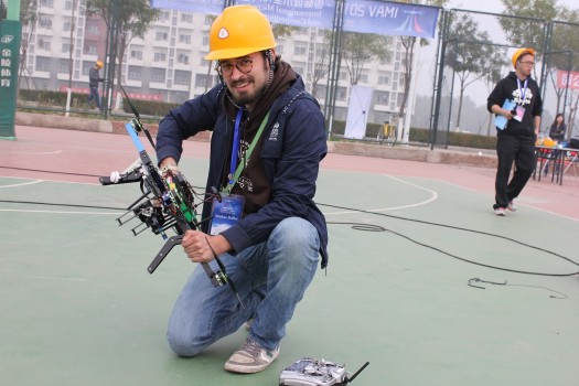
So how to prepare for 11 mission? Nothing you do on a weekend. We started roughly 6 months before the event by teaming up with TU Braunschweig’s Institute of Flight Guidance, identified missions which are also relevant for their work and created student thesis projects based on that. Still as always, most of the work happened in the last weeks before the event. Like last year, we focused on the outdoor missions. Most teams choose to concentrate either on the in or outdoor part, otherwise the amount of work would be sheer overwhelming. Yet we tried to solve indoor problems using FPV flying, because WHY NOT? In the last years we aimed for the simplest possible solution, this year we felt a little more adventurous and tried more sophisticated things: Some approaches were more successful than others. Read on for all our dirty secrets!6For the outdoor part two identical 550mm quads with 600g payload were used. As most teams we used the pixhawk autopilot with APM:Copter with an onboard companion PC. Noteworthy other components were a sonar for water pick up, a self designed PPP GPS receiver for precise delivery, lots of servos for dropping things, an IR-Lock infrared beacon for precision landing and a usb-camera on a servo gimbal for live mapping.
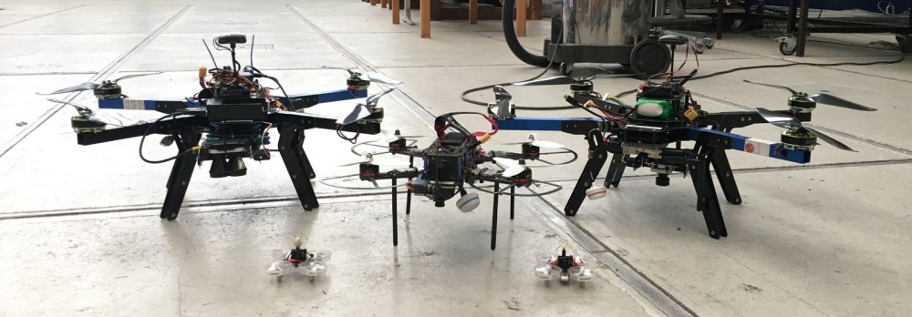
For the indoor part we used two 60mm TinyWhoops quads (For starting, entering and landing). If you haven’t flown one of these you haven’t seen the light my friend. For mapping and pick-and-release a 250mm modified fpv-racer was used. The mapping sensor was a 360° camera combined with Pix4D software.

TRAVELING TO CHINA

Limiting to little equipment was new for us and tears were shed during the selections process, but it’s possible! We’ve chosen the capacity of our batteries according to most common airplane transportation guidelines to avoid problems (max. 100Wh batteries). If you want to import multiple custom build drones to china please get the export clearance and don’t do it the day before your flight (lessons learned). By doing so importing our equipment was not a problem. Some teams were not as lucky: Their equipment was seized by the Chinese customs and releasing it took several days. Pro tip: If you forgot your clearance, distribute your stuff on all people and don’t go through customs as a prominent group with flashy boxes. The biggest problem on side was getting a chinese SIM-Card (ignore anything but China Unicom shops).

7

OUTDOOR COMPETITION

The gods of satelite navigation will come to claim their sacrifice.

TAKEOFF MISSION

The first mission consisted of starting from a moving and rocking platform. On the basis of the competition rules we built a moving platform with the same dimensions for testing purposes. It was driven by two electromotors and controlled by an arduino. An extra rocking feature was not implemented because vibrations caused by rough underground appeared sufficient. We then used the moving platform for testing the takeoff sequence. Thereby we have learned two things: Firstly we performed the complete flight controller initialization sequence on a steady surface (no moving or rocking). Secondly, to make sure the MAV is taking off stable, we set the first waypoint which will be approached by the MAV above the centre of the circle in which the platform is moving, to increase the lateral stability during takeoff.

IMG_2053.JPG

At the competition day we decided to take off from the moving non rocking platform which worked pretty good at the first attempt. Subsequently we tried starting from the moving and rocking platform which also worked fine.

LIVE MAPPING MISSION

The outdoor mapping mission was our „rabbit out of the hat“-trick to gather the last bit of extra effort to win the challenge. It was clear from the beginning that only a small amount of teams will have the time to implement and test a robust live mapping system, as the current state of the art does not provide a plug&play solution. One may ask why? Why is there no available solution for something so awesome, it allows you to overview a large area the second you fly over it? Good question, let’s hop in!

The Problem

The nature of real-time mapping involves at least the following components:

  1. UAV with camera (+ 2-axis gimbal stabilization),
  2. processing system,
  3. ground station,
  4. performant data link.

As this sounds like more or less the normal setup for offline map creation, a real-time capable system has high amounts of intercommunications, which makes a whole-in-one solution a difficult task. The camera snaps images every defined seconds, sends them to an on-board processor for further steps. Here you have to choose: Do I calculate the global map now, on-board with a waggon full of resources and take „sending out a growing global map“ as loss? Or do I reduce resources on the UAV, send out every image to the ground station, calculate a solution there and risk lost data packages on the way down? The perfect answer is: Yes!

The most time consuming part for generating high resolution maps live is the visualization. As current computer vision algorithms are rarely performed on full sized images the common approach is to resize the input images down to 20-30%. Afterwards the calculated transformation between input and global reference map is furthermore scaled back up to a wished value, which makes the process of transformation estimation quite performant and fast. However, the visualization does not benefit from those approaches as you have to finally iterate over all of your pixels to make them visible for the user. When using a 2 Megapixels camera that means 2 million iterations every defined second. That is hard to handle for regular desktop computers and even harder for embedded systems. It is therefore smart to leave the easy work for an embedded system on-board the UAV and do the visualization work with the whole processing power of the ground station. Benefit from that is, even though you lose any of the constant sized data packages (composed of image and transformation matrix) you have a global consistent solution still running on the UAV. That is especially great when dealing with a lot of radio interference on competitions. We therefore planned to fuse the two approaches into one, using the pro’s of both.

To curb your thrill of excitement at this point a little bit: We were not able to completely satisfy our goals on this one. The plan was to do the communication with LCM (Lightweight Communications and Marshalling), but in fact we lacked a proper long range wifi connection and time for robust handling. We ended up doing all the work on-board, which is okay for now, because it is only getting faster and better in the future. For a detailed look see our published conference paper.

As we were going for the real-time stitched map, we were also reaching for the stars aiming for the maximum points of 72 in this mission. When using classic approaches like offline photogrammetry without additional automation scripts other teams could only reach 18 points, which is a huge difference.

The Hardware

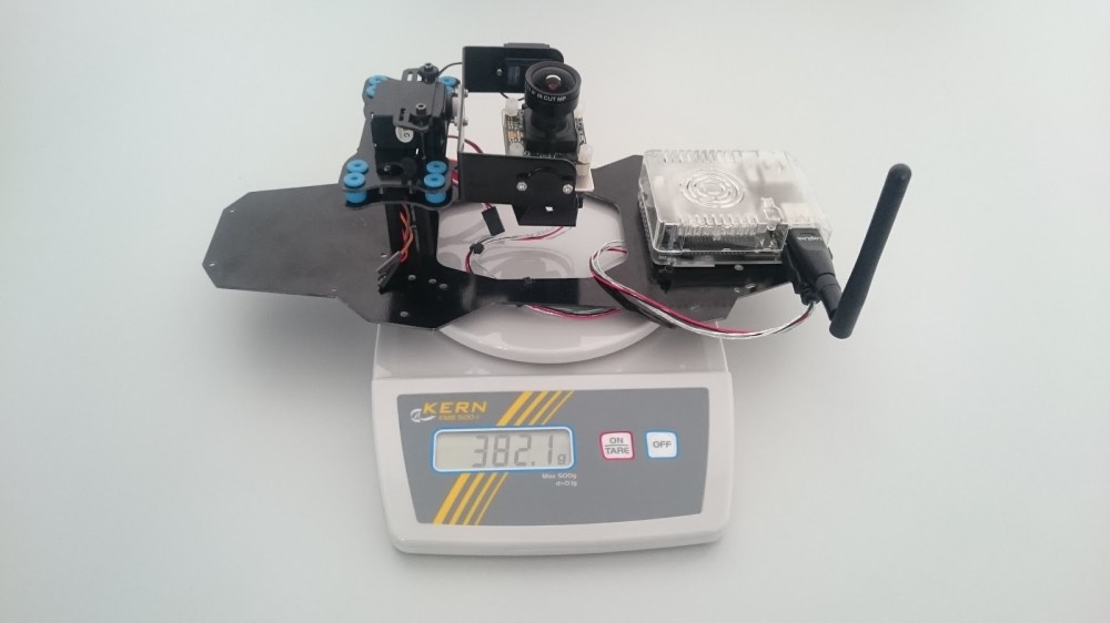
Below the mapping setup is displayed, weighing 382.1 grams in total. It consists of an UI-3251LE USB 3.0 camera sponsored by IDS Imaging Systems, a 2-axis servo gimbal stabilization and an Odroid XU4 with wifi dongle. Additionally as the wifi communication was not implemented yet, we connected a HDMI2AV-Converter (not in the picture) broadcasting the Ubuntu desktop of the Odroid via a FPV transmitter as analog video for the audience to fulfill the live streaming condition. The whole setup can be seen integrated into 1 of 2 our medium sized UAVs named Mausi the figure below. Mausi is based on an ArduCopter 3DR-D Quad kit with upgraded motors and 2.4 kg total take-off weight. It is able to fly 14 minutes and is controlled by a Pixhawk autopilot.12
The Fall

During the first practice day setting up all relevant parameters of the stitching pipeline we experienced an odd flight behaviour. While in AUTO mode Mausi oscillated around the given GPS trajectory describing the path consequently but roughly. It seemed like the magnetometer had difficulties measuring the right heading or is at least getting influenced by disturbances. After recalibration it got slightly better, but was still vermiculating despite „okay-weather-conditions“. We decided to switch the GPS modules with our second, identical setup, that ran smoothly all day. While trying to remove the I2C plug from the Pixhawk the troubles took its course.

Despite the lovely handling and encouraging words the connector went out taking most of the solder pad with it. After various tries of resoldering we had to admit, that this Pixhawk has decided to not be part of this years IMAV. Here we were, 3 days left until the competition and 50% of our outdoor hardware broke. Good. Start.

The Recovery

After falling into a deep black hole of despair a glance of light appeared at the horizon. Our friends of the Beijing Institute of Technology mobilized all their resources to organize an exact copy of the Pixhawk we broke. On the other hand the electronic powerhouse of the polish Team JEDI decided to help a competitor in need, using all their solder skills to resurrect the dead. After replacing the Pixhawk and loading the backup parameter file (professional!) and calibrating everything, the copter flipped to one side after “take-off”. The problem was solved by resetting everything there is on the pixhawk. What sounds easy as pie is actually close to rocket science, as the Pixhawk tries to desperately save as many core settings as possible and defends them like a wolfmother. It was one day left when we got it running, allowing us to finally test the live mapping setup. Who needs sleep in the first place?3

Competition day

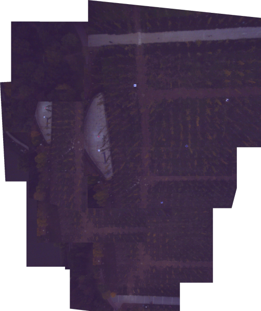
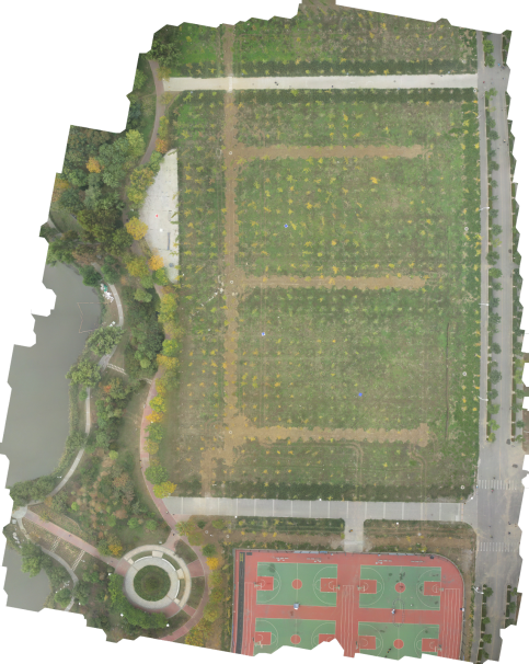
After intensive testing and 3 long hours of sleep it was clear: the mapping is going to be a gamble. The area to be mapped was dotted with small trees (see below). As the algorithm assumes the ground to be a plane every kind of perspective induced by objects is a risk of image misalignment. Additionally the position of the trees and the overall color is not unique, making it an ungrateful environment to realize an image feature based, naturally error-prone stitching pipeline. For situations like this, the implementation provides GPS-only based tracking capabilities to not lose the current position in the global map, even though an image transformation could not be calculated. To do so, the algorithm assumes that image centroid and GPS position are the same. Based on this assumption a scale from pixels to meters between two consecutive centroids can be calculated using the Haversine formula, simultaneously georeferencing the live mapping result. While this task is preferably done using Kalman filtering for sensor fusion, our code snippet was a last minute child of love featuring some ludicrous bugs. Nevertheless with the proud of a father and hope in our hearts, we dared to start the live mapping. And failed. When you decide to set the exposure time manually for more control in visually difficult environment (smog, bright concrete) you should definitely not forget to set it to a proper value at mission start…

41.jpg

5

Luckily we structured our total time well enough to start an additional try in the second run. This time with worse lighting (later day, cloudier sky), better exposure time and an addon fall-back setup for offline mapping. Just in case. We succeeded somehow with a not so beautiful, yet real-time stitched map. Luckily there were no points for consistency of the result. In the end 5 out of 6 targets can be recognized making us one of few teams solving the live mapping mission at IMAV 2016. Cheers!

DELIVERY MISSION

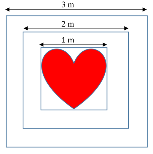
The delivery of the life buoy had a low barrier of entry in comparison to other missions like the mapping and was therefore an easy way to collect some points. But not completely without any challenges. The focus was on a precise delivery with only a small payload weighing less than 100 g. And this is where the trouble starts! How to achieve navigation with an accuracy way below 5 m? Below the life buoys and the given delivery zone for the life buoy during the competition are shown .

Initially our answer was to use a precise point positioning (PPP) GPS receiver, increasing the positioning accuracy in comparison to an ordinary GPS receiver down to some decimeters and enough to fulfill the mission requirements. At that time there was no PPP-GPS Receiver on the market, as a result we decided to develop and manufacture one on our own. As usual, it takes more time than expected and does not work on first attempt. Especially if you only have few experience with board designing. In consequence, the receiver was not working properly up to the competition. It found satellites but with a bad signal strength less than 30 dB. To achieve a GPS fix at least 4 satellites with a strength better than 35 dB are necessary.

13.png

Our guess at the moment is that the antenna path is damping the incoming satellite signals. One of many design rules for PCB layouts working with high frequency signals says the following: don’t use right angles, otherwise the signal is distorted and damped, silly human! If you look at the PCB design shown in the figure above, what can you see in the antenna path? Yes, a right angle! And that seems to be one reason, why it is not working properly. We are investigating the layout more precisely and will update this page if we find out more. In the end we decided to discard this plan and go for the standard GPS receiver, being aware of the positioning gamble.

The strategy to release the life buoy was simpler and safer. We attached the payload with a small rope to a single servo, getting it dropped to the distinct position by an easy PWM trigger. The position of the delivery zone itself was given in Lat/Lon-coordinates during the competition day by the judges. To reduce the risk of losing the GPS fix in the drop zone, we decided to deliver the life buoy at a height of 6 m, avoiding signal shading by the trees in the near surrounding.

Luckily differential GPS (DGPS) was available which increased the positioning accuracy a little bit. At our first attempt the MAV hit the 3 m circle of the delivery zone, which is really great with the described setup.

WATER SAMPLING MISSION

The main requirement for the water sampling mission was also set to a precise navigation. With only 20 ml total water volume the weight of the probe was negligible. However to achieve the demanded positioning accuracy for our initial design we decided to go for a really sophisticated approach. Our chosen strategy can be distinguished into the following steps:

  • Take off
  • Fly to the water collecting zone in a distinct height
  • Unwind a bottle
  • Take a water probe
  • Rewind the bottle
  • Fly back to the water dropping zone
  • Drop the water probe
  • Land

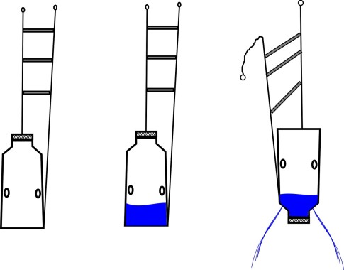
The figure further down shows the general system structure. Parts striked through were part of the initial design, but were removed during testing. To operate the water sampling mechanism a Raspberry Pi single board computer (SBC) was used. The communication link between the pixhawk autopilot and the SBC was established via MavLink over USB. To Measure the height we planned to use a LightWare LiDaR which is more precise than a barometer and capable to measure distances up to 130m. The detailed water sampling mechanism is depicted in figure below. The total weight of the mechanism is 313g.

16.jpg

To unwind and rewind the bottle, a digital high torque servo was used. The bottle can be filled with water over the site holes. To release the water probe the bottle will be pull up till the limit stop switch is triggered. By increasing the torque again the spring will be compressed up to the plug is pushed out. The communication link between autopilot and SBC was needed to trigger the SBC at the right time to perform the described sequence. For example at a distinct GPS position and height.

Nevertheless the described release mechanism worked, at least the mechanical part was working. All along the weak spot was the communication link between the autopilot and the RaspBerry Pi. And here the real story begins. We started the integration phase only one and a half week before the competition. As was expected the time ran over and the communication link was not working properly. Unfortunately the servo gave up working during integration. Additionally the design of the driver for the wind was crude and too complex. Arrived in china, we gave it a last chance for one test. But also the final test was unsuccessful, by still unknown reasons.

14.jpg Up to the last minute

We had a self-given deadline until which solutions had to work or they were replaced. Sadly the communication link to the winch based water sampling didn’t work until this date. In consequence we dropped it and went back to a simple servo-drops-something solution. But what shall it drop?

15.png

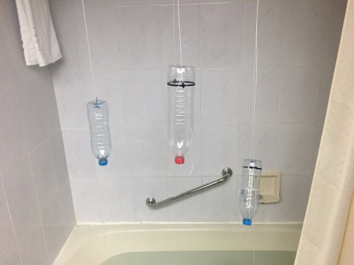
To speed up the whole process, we made up a small challenge. We build up three different mechanisms and chose the best. You can see the result of the challenge on the figure below:

The idea of the final design was as following. Take a bottle with fill in holes at the center of the bottle and attach two ropes to the bottle, one at the neck and the other at the bottom. Both ropes are fixed by a single servo at the MAV and can be released independently. In comparison to the initial design we had no wind. Thus the problem was that waypoints underneath 0 m can not be approached by the autopilot, so there were approximately 6 m of rope attached underneath the UAV to compensate air pressure fluctuations. The smallest squall is sufficient and the whole thing starts turning. Therefore we attached chopsticks in the same distances to each other, to avoid unintentional twisting of the ropes. To drop water the rope attached to the neck of the bottle will be released first, as shown in the figure above.

We were not sure to meet the dropping zone exactly. Even though to reach the water tank we attached small holes at the neck of the bottle which peformed like a shower head.

Lessons learned

Even though finally the initial design was not working it was a great experience and we have learned a lot. The most we have learned is that a complex system takes at least 20 percent of the scheduled time only for integration. So start on time!

19.png

PLATFORM LANDING MISSION

In the early design phase we decided to use the pixy cam with an associated IR beacon for precision landing, because of the easy integration in the pixhawk autopilot system. The whole computer vision process is directly done on the PixyCam and you don’t have to think about it. The connection between autopilot and PixyCam was established via I²C. Basicly the sideways divergences to the target will be transmitted and handled by the autopilot. The camera is equipped with an IR filter to prevent visible light interferences. In addition the IR beacon emits a specific LED pattern at a distinct frequency increasing the redundancy all the more. As the initial approach we attached the pixy cam with a gimbal under the MAV. However the achieved results were even worse the direct mounted cam. Therefore we attached the camera without any gimbal directly under the MAV, which worked pretty good.

The precision land was tested on static and moving targets. Tests resulted that the MAV is following a moving target up to 1 m/s ground speed. At higher speeds the IR beacon is moving too fast out of the field of view of the pixy cam and the MAV loses the track. On static targets we reached a precision between to 5 to 10 cm.

At that point we realized it was too challenging to implement a precision land on a moving platform with the chosen sensor, so we decided to approach at the competition the land only on a static platform.

To get a more precise view of the capabilities of the sensor we build up a simple debugging tool, to observe the status of the camera during flight, to get to know if the beacon is in the field of view or not. Therefore we took advantage of a simple status LED on the camera module. The LED was performing exactly what we need, but sadly too dark. So without further ado we placed a big LED array, to ensure visibility from the ground. Mostly we were interested in the field of view and the resulting recognition range for better path planning later on. In general the autopilot is processing the measured sideways distances as soons as the the MAV is in land mode and is performing from there a precision land. Which means the last waypoint, before land, should be near to the beacon. The results of the tests revealed that the camera reliable recognize the beacon in a height up to 12 m and a radius of 3 – 4 m.

Well prepared for the competition, we performed on the competition day a precision land on the static platform at the first try.

INDOOR COMPETITION

The indoor part took place in BIT’s indoor sport arena. A one story building with 4 rooms, one door, one window and one chimney was set up, the missions were

  1. takeoff from moving platform
  2. entering a building
  3. mapping the building
  4. picking up and releasing specific objects
  5. exiting the building
  6. landing on the platform

1

ENTERING BUILDING MISSION

Unlike the outdoor part, FPV flight was (still?) allowed indoors. We choose to fly everything FPV since the implementing of a robust LiDAR or Vision based navigation would have been too time consuming. Takeoff, entering, exiting and Landing on the plattform was done using a TinyWhoop FPV Copter. Due to the size of only a few Centimeter the size factor was high and we were able to master all the planned tasks on the first flight without any problems. The original FPV footage can be seen on youtube.

2

PICK AND RELEASE MISSION

A solution for picking up and releasing the small buckets was realized using a modified 250mm FPV racer. The vehicle was equipped with propeller protection to minimize the impact of contact with walls etc. A servo controlled “lance” was mounted in front of the FPV camera in order to pick and release the pucket. Initial tests showed that the collecting of the bucket was hard due to its location on a table. The downwash of the approaching copter would interfere with the table surface right before the copter would reach the bucket. This situation impeded the manual altitude control heavily making it really hard to hit the small target with the lance. The attempt to solve this using a downward facing ultrasound sensor were not successful due to difficulties in tuning the altitude control loop on short notice.

3

Therefor the landing gear was extended to a length which allowed the copter to land in front of the bucket and pick it up using the lance once the servo was triggered. When the vehicle hovered over the target area, the bucket would be dropped using the servo. Aiming was realized using a second FPV camera/transmitter combo. A Copilot was then needed to guide the pilot. While the bucket collecting and releasing worked under good conditions in our lab it didn’t on the test side. The available space for landing the copter on the table was so small that every small error caused the copter to hit an object, causing a crash. Yet no other team managed to do this either.

We lost a lot of landing gear in these crashes. Luckily we found a greatly available resource for replacement: chopsticks!

360° MAPPING MISSION

The indoor mapping mission was another challenging task. The tasks stated that 3 unknown rooms had to be mapped. Most points were given when the created map was in 3D and the furniture in each room recognisable.

Since we had little expierience using LiDAR or optical SLAM algorithms we decided to use offline photogrammetry for mapping. We had good results using commercial software like Agisoft and Pix4D in outdoor scenarios and wanted to use these idoor too. UAV based photogrammetry is a little tricky indoor, since you need to plan your flight more carefully to garantee the needed overlap in every image. Spheric (also known as 360°) cameras seemed like a clever solution to garantee this overlap while recording the room in any angle (no missing information). Pix4D also started supporting 360° images and named the Ricoh Theta S as the lightest supported camera, which we therefore used. We mounted the camera on the 250mm racing quad and started testing.

01-800x800.jpg

The camera can be controlled with a smartphone app and many settings can be set manually. The camera produces good spheric images and videos without any additional processing. The biggest drawback is the limited final resolution (Video 2MP / Photo 14MP). The created images and videos looked stunning, this technology is here to stay. The results from our mapping approaches were also good, IF the conditions were good. The image displays a dense cloud created with Pix4D using 360° images on the attic of the IFF. You can also see the 3D point cloud on sketchfab.
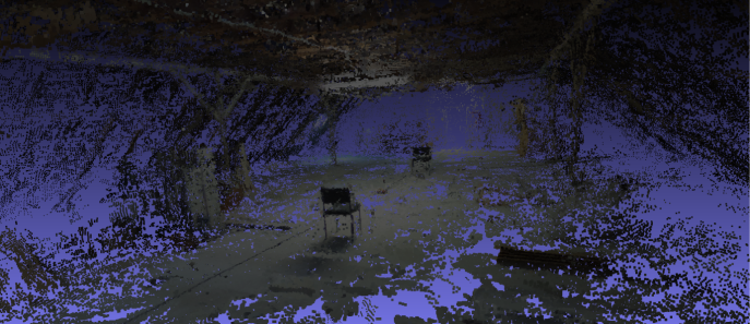
mesh.png

The software was able to create good results when all of the following criteria were fullfilled:

  • a lot of overlap (like ~10 images per room or every ~0.5m)
  • a lot of features (no regular white walls etc.)
  • enough light (beware of neon light frequency induced artefacts)
  • static scene (try to hide behind the camera… oh!)

When any of these criteria weren’t met Pix4D wasn’t able to align the images. In the current state, the workflow is much more sensible regarding these disturbances compared to “regular” images, therefore the use of 360° cameras didn’t really simplify the process.

For mapping the camera was put in interval shooting mode (one image every 8 seconds at full resolution) while the vehicle was slowly flown through the rooms using FPV. The processing took about 15min (using low quality settings). Sadly the mapping did not work in the rooms prepared for the IMAV indoor competition. The main reason beeing the lack of features. While the walls were covered with bits of tape, this was not enough. Also, the walls of the building were very sleek, which lead to always changing reflections of the light sources. This 3D point cloud was the successfull result we got during the test day.

room.jpg

FINAL WORDS

We learned a lot in the weeks leading to this event and hope we were able to pass on some of our insights. Team AKAMAV will be in Touluse at IMAV 2017 to meet all of you wonderful nerds. We are always curious to meet new people! If you are a student, drone enthusiast or professional who wants to contribute, learn or simply geek around with us, please come! We have much more ideas then time on our hand.

Outdoor Competition Scores

  1. AKAMAV, Germany 279.7
  2. ISAE, France 225.6
  3. SCV, Korea 205.7
  4. AUTMAV, Iran 167.4
  5. FanSO, China 155.3
  6. JEDI SG, Poland 84.4
  7. MRL-QIAU, Iran 84.0
  8. BlackBee, Brazil 63.6
  9. MAVLab, the Netherlands 57.6
  10. Cigogne, France 46.2


Indoor Competition Scores

  1. KN2C, Iran 423.9
  2. Quetzalcuauhtli, Mexico 361.7
  3. MAVLab, the Netherlands 271.1
  4. CVG-UPM, Spain 268.1
  5. JEDI SG, Poland 253.1
  6. ARC, Iran 218.3
  7. AUTMAV, Iran 198.6
  8. UI-AI, Iran 81.2
  9. AKAMAV, Germany 43.8
  10. MRL-QIAU, Iran 21.8
  11. Persian Gulf, Iran 20.9
  12. BlackBee, Brazil 0
  13. EuroAvionic, Poland 0

Last but definitely not least we want to thank all of our sponsors, namely the Institute of Flight Guidance, TU Braunschweig, GOM GmbH, IDS Imaging Development Systems GmbH and u-blox Holding AG. A special thanks goes out to our team leader Mario Gäbel for doing so much development work and still being able to manage and organize our tour and financial paperwork. Also a big shout out to the rest of the team, namely: Benjamin Hülsen for rock-solid electronic layouts, Dimitri Zhukov for unbreakable constructions, Alexander Kern for computer vision that never stops tracking, Endres Kathe for not marrying an Arduino and Markus Bobbe for destroying only one of our Pixhawks.

Happy Flying!

Read more…

3DR Solo now with RTK !

3689707799?profile=original

First of all, Happy New Year Community ... We wish you a Happy flight year ! 

Good news for Solo owners, we just released 2 versions of Solo GPS to replace your factory GNSS. One with u-blox NEO-M8N or NEO-M8T and one with u-blox NEO-M8P

3689707747?profile=original

3DR SOLO RTK GPS (NEO-M8P) 

The only RTK GPS based on u-blox NEO-M8P for 3DR SOLO. 

Key features:

  • Centimeter‑level GNSS positioning for mass market, based on U-Blox M8P
  • Integrated Real Time Kinematics (RTK) for fast time‑to‑market
  • Smallest, lightest, and best energy‑efficient RTK module
  • Antenna patch
  • Power filter, ESD protection, overvoltage protection
  • Receiver type: 72-channel GPS L1 , GLONASS L1, BeiDou B1, GALILEO E1
  • Nav. update rate: up to 8 Hz
  • Position accuracy: 2.5 cm
  • Connectors: USB micro, Clik-Mate
  • Weight: 16g

You can use our new RTK Base Station based on u-blox NEO-M8P with this product http://drotek.io/2i3NcdW

3689707875?profile=original

3DR SOLO GPS (NEO-M8N or NEO-M8T) 

Upgrade your solo with the last u-blox module for 3DR SOLO. 

Key features:

  • Ublox NEO-M8N or NEO-M8T
  • Plug and play on 3DR SOLO
  • Antenna patch
  • Power filter, ESD protection, overvoltage protection
  • Receiver type: 72-channel GPS, GLONASS, BeiDou, QZSS, SBAS and Galileo
  • Connectors: USB micro, Clik-Mate
  • Weight: 16g


Products will be available for shipping from January 20st. Due to high demand, preorder your GPS to ensure delivery from this date. 

Read more…

Evolution of our prototypes. PART 2

3689708574?profile=original

Link of our Droiko on Kickstarter: Kickstarter Droiko

If you have any doubt, comment in the box below.

Another picture from our first fully functional prototype. We used rubber bands to hold the battery.

3689708649?profile=original

Comparison of electronic PCB. The large green one is from our first fully functional prototype, the small blue one is our latest pcb prototype.

3689708784?profile=original

Our latest pcb design mounted on our latest prototypes.

3689708817?profile=original

Almost final prototypes. The ones we took to the Maker Faire Rome 2016.

3689708736?profile=original

Closer details of almost final prototype. Chassis is 3D printed and spray painted.

3689708896?profile=original

Almost final prototype next to final checkpoints.

3689708918?profile=original

Black latest prototype.


Read more…