All Posts (11086)

Sort by

Moral to the story: Avoid buzzing Alcatraz.

3689466129?profile=originalThis seemed to get very little uptake in the mainstream media... perhaps for the better.  Nevertheless, I thought it was worth sharing here:

From the article:

Two Marin County men were cited by federal authorities over a drone helicopter buzzing around Alcatraz Island, the National Park Service reported.

The operator of the remote-controlled helicopter, which is equipped with high-definition cameras, was Devin Hedrick, an aerial photographer who lives in Greenbrae. Hedrick's service, Hover Effect LLC, offers airborne video and still photography for real estate listings, music videos and television shows.

On Tuesday, working from a boat on the bay, Hedrick was operating the electric helicopter for a client, Bruce Paquett of Sausalito, whose project involves images of Alcatraz. According to park service spokeswoman Alexandra Picavet, the helicopter, which has a rotor span of about 6 feet, was flying low around the island, frightening the birds and swooping over the tourists' ferry dock.

The U.S. Coast Guard, carrying a National Park Service ranger, approached their boat and confiscated the video. After watching it, the park service issued citations to both Hedrick and Paquett.

"Their own footage showed us what they were doing, which was scaring the shorebirds from their nests and getting too close to the people on the dock," Picavet said.

Hedrick was cited on suspicion of disturbing wildlife, operating aircraft within 500 feet of a boat dock, creating hazardous conditions and operating an aircraft within the Federal Aviation Administration-imposed closure of 2,000 feet above the island.

Paquett was cited on suspicion of filming without a permit.

Alcatraz is part of the Golden Gate National Recreation Area, which is managed by the National Park Service.

Hedrick, reached by telephone, said he thought the boat was 500 feet away.

"There certainly are some things I should have been more clear about, instead of just taking the advice of the boat driver," he said.

Read more…
Developer

SIM Development update - Now in 3D

3689466202?profile=originalThis is a quick update for the Arducopter SIM and 2.6.1 development:


There is quite a bit of development going on right now, but I thought I'd share what I'm working on. I'm using Flash to implement a simulator and test Arducopter code. What's on my site at jasonshort.com is on the current Trunk. 

What isn't there is a whole lot of other work including Tridge's DCM core updates and Andreas' APM_limits code which is a geo-fencing library. 


You'll notice the sim has been updated to work in 3D now, so you can fly full missions, Yaw and Loiter in 3D. An orange line now indicates nav_yaw which is the yaw hold angle. A black circle indicates the GPS positions and the red box is the next waypoint location.


A new crosstrack algorithm:

Based on our flights in high winds at the Copter Rodeo, I set out to improve our crosstrack error correction. We had previously been using Arduplanes' track correction which turns the plane into the error to correct it. Of course copters can fly sideways and don't need to give up forward momentum to track correctly. The new algorithm solves this and acts very similar to the loiter control. Crosstrack gain will be lowered to a default of .2 because of new approach.


GPS lead filter:

Another idea from the rodeo, the lead filter takes into account the velocity and acceleration of the copter and the latency of the GPS to guess where the copter really is, not just where it was 1 second ago. This helps Loiter somewhat, but where it really shines is the Waypoint and RTL navigation. When you hit the WP it acts immediately, and not 1 second later which helps reduce overshoot.


Altitude hedging:

Phillip Jones suggested prioritizing the altitude over navigation when fighting wind to prevent the quad from loosing altitude during a hard pitch. This keeps the quad from hitting the ground during WP flight. Anything greater than a 1m error begins to level out nav_pitch to gain altitude. Still a WIP and not on the trunk yet.


RTL:

RTL_altitude is now implemented. This will cause the copter to rise to the desired altitude in Loiter before heading home. The parameter rtl_approach_alt will change how the copter will land after RTL or a mission that doesn't end in a land command. Basically setting this param to 0 will cause a land, setting this to any other number will cause the copter to go to that altitude after RTLing. The param auto_land_timeout is used to trigger this altitude change. The RTL Approach altitude parameter is great for bringing the copter down without worrying about touching the ground.


Alternate Yaw control:

A new control method for Yaw goes back to the hybrid rate/stabilzie approach, but uses a timer to lock in the hold angle. This allows the rate controller to brake the Yaw and then set the new hold angle without much overshoot and dreaded snapback.


Better Yaw gains:

Testing the SIM with an out of alignment motor allowed me to test various I term settings. An iterm of .02 for BOTH Rate and Stabilize Yaw works best.


Discovered Yaw Bias issue:

While running missions in the sim I realized the copter would run off track while Yawing to the target. Turns out we change and update Yaw continuously, but the copter's nav_roll and nav_pitch is only updated 4x with GPS reads. This causes the copter to be pitching at at angle to the target instead of towards the target when Yawing. The nav_roll and nav_pitch are now updated at 50 hz instead of 4 which get's rid of most of the issues.


Self centering throttle:

This is very experimental, and probably won't be enabled by default. The throttle cruise value is calculated at all times, and the lower limit of throttle is raised to place that cruise value right at mid stick. 


Drag/velocity estimation:

Takes the desired velocity and outputs a pitch and roll that should match the drag of the copter. This lets the I-terms deal with just the wind and not the wind + drag combined. It also helps the track accuracy by about 30%.


Alt Hold:

"Angle boost" a more accurate algorithm in 2.6, but we found it didn't account for the inefficiency of the thrust pattern. A small correction has been added to account for this.


Throttle min and max 

Implemented the params for throttle min and max so you can change them from the MP.


What's new with the SIM:

Added new top view

Added 3D physics

Added the ability to run the SIM at up to 10x speed for running variations

Added a Score for integrating crosstrack error to use for gradient descent (machine learning)

Added a new joystick controller class that acts like a real radio, or allows user to adjust 1 axis only.

Added 2D wind

Added Yaw Gains

Added iteration # limit to stop the sim after N number of 100hz main loops.


What's next in the SIM:

Mission editor


If you are testing the trunk, please check the SIM and see if you can reproduce bugs. If not, please note that in bug reports.


Code is here:

http://code.google.com/p/ardusim/

Flash FLA project file available by request.

Jason


Video from WIP last week.


Read more…
3D Robotics

Navigating UAVs without GPS

3689466060?profile=original

From Gizmodo: 

Military drones rely heavily on GPS for navigation guidance while in the air. But in areas where a signal can't be found, or where someone is using a GPS jammer, a drone will find itself in a troublesome predicament. Military sub-contractor BAE Systems has come up with a solution to that problem: Apositioning system called NAVSOP that uses any wireless signal to find its location.

The genius of NAVSOP (Navigation via Signals of Opportunity) is that it really doesn't matter what the signal is. It can be a TV signal, radio signal, wi-fi signal, or even a GPS jamming signal. And the part that excites BAE is that the infrastructure is already in place. They don't have to build out a network of transmitters. What excites us is that it works indoors, meaning if this was integrated into all navigation products—and not just military tools—we could have powerful location assistance services indoors and in dense cities. The BBC says that the NAVSOP box requires GPS at first to learn about its surroundings. But over time as it amasses a database of location information, it will become less and less reliant on GPS.

The system is currently a prototype box that can be linked up to whatever is in need of navigation assistance, but BAE believes it can be shrunk down into a dongle-sized package.It's like the navigation equivalent of the tech Bruce Wayne used in Batman Begins to see through walls using people's cellphone signals. [BAE via BBC via Engadget]

Read more…
3D Robotics

3689465944?profile=original

Hackaday found a paper that describes a GPS spoofing technique that may be similar to that used by Iran to bring down a US drone. From the paper's abstract:

In this paper, we investigate the requirements for successful GPS spoofing
attacks on individuals and groups of victims with civilian or military
GPS receivers. In particular, we are interested in identifying
from which locations and with which precision the attacker needs
to generate its signals in order to successfully spoof the receivers.
We will show, for example, that any number of receivers can
easily be spoofed to one arbitrary location; however, the attacker is
restricted to only few transmission locations when spoofing a group
of receivers while preserving their constellation.
In addition, we investigate the practical aspects of a satellitelock
takeover, in which a victim receives spoofed signals after first
being locked on to legitimate GPS signals. Using a civilian GPS
signal generator, we perform a set of experiments and find the minimal
precision of the attacker’s spoofing signals required for covert
satellite-lock takeover.

Read more…

Traditional Helicopter 2.6 Loiter Test

As some of you know i have been trying to get my heli to Loiter since last year. Today i got the heli to Position Hold for around 3 mins, it would have gone longer but it was blowing a gale, and starting to rain, so i cut it short.

So after a few more tests with this heli, more tuning etc i'll be starting the on the much larger Gas Helicopter, 23cc. 

I tried to download the logs but didnt really get anything out of the APM that would have been any use. 

Sorry about the poor quality of the video, i only had my stills cam with me, but you can see from one shot i'm pretty relaxed letting it fly. The Loiter P value is down to 0.100 which is really low, i may raise it slightly, will wait for a much calmer day to get better results. The CH7 autotrim worked really well, had to do it on  windy day but no choice. 

I'm going build on this test and try to get the razor more stable. 

Thanks to Randy, Robert for the Heli code, Martin @ buildyourowndrone, and all the other programmers, testers, builders,  for all your hard work.

Read more…

3689465827?profile=original

After the Latest Skywalker crash I decided that the build-fly-crash-build-(repeat) process was too slow, and I wasn't learning as fast as I'd hoped. 


I'd seen an ad at Hobby King for $20 Quadcopter frames... sounded like a good deal and I already had a matched pair of motors/ESC and APM2 so I decided to take the plunge and order the balance of the components needed to build a basic quad copter.

The motors were Detrum 810kv's with 25A ESCs from HobbyPartz.  I'd picked them up to experiement with twin fixed wing stuff and small wings...

Assembly was easy, though I was short on bolts/screws.  No big deal.

HobbyKing 550mm Quadcopter frame

4x Detrum 25A ESC

4x Detrum 810kv

APM2


Below are pictures of the finished quadcopter and then some videos from today.  My 11 yr old was cameraman... kinda shakey...  Yes, the "fuselage" is a potato salad tub from a local deli.


3689465842?profile=original3689466017?profile=original3689466032?profile=original

3689465965?profile=originalhttps://www.youtube.com/watch?v=OlHMXWs-exQ

https://www.youtube.com/watch?v=nVfJLeLKtEA

Read more…
Developer

a3088719-168-Intermezzo-100-A-Front.jpg?width=500

(Image linked form Rc Groups)


Hi Guys,

This is my second blog post on my project to design a drone from scratch. The previous post did its work and served its purpose for crowdsourcing the required electronics. Martin(Distributor)of Build Your Own Drone gifted me a whole lot of parts i.e a full APM 1 setup and Motors,Props and XBees and it is with these parts I started building the drone.

Airframe:

I had chosen to go with a Kline–Fogleman airfoil design, and found Jaron's RCgroups blog. For the time being, my aircraft will be a clone of his Intermezzo 100. Since Jaron has been kind enough to provide the DXF files for laser cutting, I had hoped that would get it lasercut locally.

Unfortunately, I haven't been able to find any laser cutters here in Kolkata and am hoping that someone who has a CNC and a supply of Depron,plywood etc. will be able to lasercut the template and send it to me(to India). I know that its a bit of a steep request, but its the only way. If you have a CNC and access to Depron and plywood,etc. please help me!

Electronics:

The current electronics are a stock APM setup, with the exeption of R/C electronics as I will be controlling it using a joystick and XBees.

Read more…

Evolution of a position tracker


vision36.jpg


So the red/blue marker failed when flying over an upward facing light caused all color to be lost.  Sensor saturation makes any color based marker unworkable. 

There is a glitch prone way to fix the white balance on the webcam.  It has to be fixed before capturing the 1st frame.  That made the LED white always come out white & the CFL ambient light turn yellow.  It was potentially an easy way to separate out the background until you realized CFLs are being superceded by white LEDs.

vision37.jpg

If the lighting pointed down, the whites couldn't be separated from the CFL & colors were still lost.  The webcam can still knock out the color saturation with an ND filter.


Next would be flashing the LED.

vision43.jpg


vision38.jpg

vision39.jpg

An anti static bag as an ND filter got it down enough to resolve color from LEDs. It actually seemed robust enough to handle different distances.


vision40


Without paper


vision41

With paper.


vision42

The best arrangement has the LEDs in opposing directions & colored paper.  The paper adds more coverage.  It's really a slight difference.  Without paper, it's a lot lighter, but any production version would use paint.

A human looking at this thinks there must be a way to detect the inner red edge & extrapolate a circle.

It's not clear why the color facing out is overwhelmed by the color facing in or why the blue has a red outline.  The shape while rotating is completely different than stationary.

A hard edge is required to get an accurate semicircle.  So another algorithm emerges.  Once again, scan for all the red blobs.  Take only blobs with a minimum number of adjacent blue pixels.  Take the center of the largest blob as the center of the circle.  Test rays from the center.  Take all the points where the ray turns from red to blue or off.  Extrapolate the circle dimensions & center as with Marcy 1.

A rough experiment could just scan all the red pixels & skip blob detection, but if someone flies in a room full of red LED's, there's going to be a problem.

 
vision44.jpg
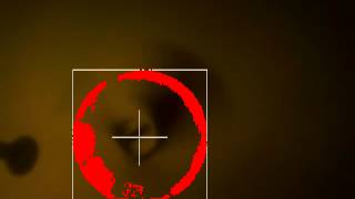
So much for that.  The circle isn't always contiguous.  It's more of a camera limitation than an algorithm flaw.
vision45.jpg


The worst the camera did.  Those red gaps between the blue are also a problem.  All roads lead to another board camera.

vision46.jpg

vision47.jpg


Various errors

vision48.jpg
An ideal outcome.

Then came flashing LEDs & just the red LED.  Flashing was pointless.  The red bleeds too much & the blue has red fringes.  Having just the red LED was promising.

vision49.jpg

 Without paper.

vision50.jpg


With paper.  It unexpectedly showed a hard edge.

Maybe 2 red LEDs would be better.  A new algorithm slowly emerges, in which the largest blob from each frame is detected before the accumulator.  Then, the accumulated blobs are measured.


vision51.jpg

Position sensing with this level of detection has already been proven.


Position tracking in ambient light is really starting to gel.  These were hopefully worst case scenarios.  The typical use would be a room with fluorescent lights pointing down from the ceiling or fluorescent lights pointing up through a lampshade.


Blob tracking as opposed to Marcy 1's straight luma keying is definitely required.  The red LED won because there isn't a trend toward replacing CFL's with red LED's like there is with white LED's.  


Red shows pure red.  Blue has a ring of red around it.  A white LED shows blue & red.  Not sure how a room lit with white LED's would handle.  It would definitely take feature detection, with a POV pattern under the wing.  Maybe throwing out blobs with adjacent blue.

Takeoff is a real unknown, requiring the camera to be too close.  A fisheye lens might improve matters.  Those jelly bean lenses might drastically change the camera algorithm.  It just takes 1 week to order anything.

There's basically making it statically stable on the takeoff stand or pointing the camera diagonally, to extrapolate attitude from the mostly unseen disk.


vision52.jpg
The $30 wide angle lens was pretty disappointing.  Still needs 16" of clearance to see the full disk.


After giving up on actively stabilizing the takeoff attitude, because there's no way to determine attitude with the current camera position, a quick spin up showed she could be made passively stable on the takeoff stand & didn't naturally oscillate in a hover.

So the takeoff attitude is stable on the current stand & below the takeoff power.  Before the takeoff, there's a power level at which the attitude is unstable.  Then it takes off, but the camera can't see it until it's pretty high.

Her 1st hover was still a Chinese toy, purely manual throttle & no cyclic.  The ground based vision was able to track the marker LED in ambient light.  All that's needed is functioning camera gimballing & position sensing to finish the flight portion.


Pulling off the takeoff with the current camera position is rough.  There's hard coding a starting throttle, then increasing throttle until the period hits a certain range, then instantly stepping it up to a known takeoff power so it doesn't take off faster than the camera can gain a position lock.

There's just tracking the 1st accumulated blob of minimum size.  When all 4 sides are in frame, begin calculating position.  That only happens after some climbing.

Finally, there's the question of using an alt/az or equatorial camera mount.  The camera is in the center of the flying area & can't break contact to flip around.  The servos only do 180 deg, necessitating an equatorial mount.  An alt/az mount couldn't maintain constant contact if it was orbiting directly overhead.
WEBCAM VS BOARD CAM
A webcam is all but useless & unaffordable.  The actual camera would be a board cam, able to stop down enough to knock out all color saturation.  The exposure must also be long.  It would be much harder to track if there were gaps in the circle.
There are ways to make an IR camera, but you know why those Vicon rooms don't have windows.
The availability of one hung low brand webcams for $3 makes one doubt the viability of $10 board cams. Webcam rolling shutter & scan rate is worse.   They're much bigger than the $10 board cams.  Webcams continue to have very large circuits, in addition to the camera module.  They wouldn't be practical on the aircraft.  The 1 hung low brands don't have enough manual control.

A ground cam with 2 USB cables is impractical.  To manage the number of USB cables, the leading strategy is a ground IR receiver controlled from an airborne IR transmitter.

The problem is you need to send a compass reading from the ground camera.  
webcam01.jpg

Despite the 2 junk webcams in the apartment, they're not useful since the final product is heading towards a 2nd custom board, with a board cam.  It's easier for the servo PWM, magnetometer, & manual camera control to be on 1 chip.


DESIGNING AN EQUATORIAL MOUNT
As predicted, a ground based camera gimbal needs a lot of labor & parts to assemble.  The trick is finding the simplest, most compact, uniform parts.  The software for aiming the equatorial mount is also a buster.


vision53.jpg


equatorial05.jpg
 
equatorial06.jpg
 
equatorial07.jpg


vision54.jpg

So the minimal cost equatorial mount ended up a lot bigger than the alt/az mount, even with the micro servos.  The mane reason is the servo  shafts aren't in the middle, so the attachments need to clear a very wide box. 

You'd think servos would have evolved to have centered shafts by now, but the old 1 sided shaft is the most efficient design.  The mount could be smaller, by using more complex parts.


 Next came the most compact equatorial mount, using more unique parts.
equatorial01.jpg
 
equatorial02.jpg
 
equatorial03.jpg
 
equatorial04.jpg
 
It's definitely smaller than the alt/az mount.
 Considering the uninterrupted hemisphere view, it's surprising more antennas don't use equatorial mounts.  The next great task is software to aim it.

Given X & Y in the image, calculate the direction in the ground plane & the servo steps to center the image.  X & Y in the image aren't X & Y to the servos.  It takes serious highschool algebra to convert between image & servo reference.


Read more…
100KM

Techpod Prototype Build Blog


IMG_20120626_031406.jpg?9d7bd4&width=500

Hey everyone . the long awaited day has come . the prototype was delivered to my house via UPS .I took a few pics as I unwrapped it . The guys at airborne models tell me the packaging will match the production models so this will give everyone a good idea as to what will show up in the mail when you order one . The airplane came inside of 2 double layer boxes with a layer of 1/2 inch foam lining the inside of the inner box . Every piece of foam was carefully wrapped in foam and neatly placed in the box . Every small piece was bagged .Very impressed and they do a much better job than I could . Here are some pictures .

IMG_20120625_1435371.jpg?9d7bd4&width=500

IMG_20120627_135453.jpg?9d7bd4&width=500

IMG_20120626_0315371.jpg?9d7bd4&width=500


IMG_20120626_0318301.jpg?9d7bd4&width=500

I will be posting more pics as i build it over the weekend

read more at hobbyuav.com


Read more…

I was pleased to see a cool laser rangefinding project on Kickstarter- I hope this project gets fully funded (and I'm a backer). I've actually been experimenting myself with structured light and laser rangefinding using our ArduEye hardware and thought I'd share it here.

3689465772?profile=original

The setup is very simple- An Arduino Pro Mini serves as the computing backbone of the device. Via a 2N2222 transistor (I know I know...) the Arduino can on and off a red laser module. The Arduino is connected to an ArduEye breakout board with one of Centeye's Stonyman image sensor chips and a cell-phone camera lens. The whole setup (excluding the red FTDI thing) weighs about 10.9 grams. I think we can reduce that to maybe 4 or 5 grams- the laser module weighs 1.9 grams and is the limiting factor.

The principle of operation is straight forward- the laser is mounted horizontally from the image sensor by a known baseline distance. The Arduino first turns off the laser and then grabs a small image (3 rows of 32 pixels in this implementation). Then the Arduino turns the laser on and grabs the same pixels. The Arduino then determines which pixel experienced the greatest increase in light level due to the laser- that "winning point" is the detected location of the laser in the image. Using this location, the baseline distance, the lens focal length, the pitch between pixels on the image sensor, and basic trigonometry, we can then estimate the detected distance. I haven't yet implemented this final distance calculation- my main interest was seeing if the laser could be detected. The above video shows the system in operation.

In practice, I've been able to pick up the laser point at a distance of up to about 40 feet- not bad for a 2 mW laser. In brighter lights you can put an optical bandpass filter that lets through only laser light- with this the system works at distances of say 10 feet even in 1 klux environments e.g. a sunlit room. If you are using this for close ranges, you can turn up the pulse rate and grab distances at up to 200Hz. How does an Arduino grab and process images at 200Hz? Easy- at 3x32 it is only grabbing 96 pixels!

Read more…
Moderator

3689465693?profile=original

An exploration into the fascinating world of competitive indoor free flight aeronautics.  Beautiful cinematography -- I had to watch it twice to realize some of the clips weren't in slow motion, but in real time.  And a surprisingly interesting group of flyers as well.

Help put this project over the top!

http://www.kickstarter.com/projects/bensaks/float-documentary

http://vimeo.com/18557380

Read more…

Eagle Shot

We are doing Aerial Shot across the bali Beach few days a go. Suddenly an Eagle came and chase our Bixler... After dancing and manuvering around we manage to go on top, and point the camera to the eagle... Yes we are lucky to get the perfect shot...

3689465627?profile=original
Recorded from the ground, i think the eagle mean no harm to our plane... may be he just exited to see new friend on the sky.... Who said eagle flies alone ? :D

3689465705?profile=original

Read more…

3689465312?profile=original

Want to Make an Antenna Tracker?

I am making this blog more for my future self than anyone else.  That said, I think a lot of people will appreciate the contents as they too might have found that an antenna tracker (AT) build is not easy to find, nor are the explanations as to why they are built the way they are.  I AM NOT AN EXPERT but I plan to show you how I pulled it off and therefore establish a "baseline" for anyone building their own antenna tracker.  If you are ever confused as to which "whatever" I am referring to below, default your brain to aircraft and, good luck!

There is a lot to say here, so bear with me as I go over the basics.

What is an Antenna Tracker (AT)? 

An AT is system that tracks where in the sky your plane/copter/whatever is.  There are multiple methods for an AT to do this with.  One is to use RADAR to find your plane (or copter or whatever) and feed the altitude/angles to the AT, this is way expensive and beyond the DIY needs.  Another way is to have your plane emit a signal (or two) and a receiver on your AT electronically compares what it receives and uses that information to point the antennas with. This works as one emitted signal is slightly weaker than the other.  There is an off the shelf system within DIY budget but if you use that system then it is usually not compatible with other "bells and whistles" you might want to put on your own AT. 

The way the APM Mission Planner does it (that's the GCS software DIYdrones hosts, among others) is far more simple and yet very much as effective as the other two methods.  Since your GPS on the APM board is already tracking where your plane is, it simply takes this data and shoves it to your AT and voila! instant tracking as good as your GPS can track it!  My build uses the APM Mission Planner (MP) in conjunction with the APM2.

Why should I build one?

Easy.  Two things, first it allows you to use a category of antennas broadly referred to as directional antennas.  There is the Yagi and the Patch style as the most commonly used.  These suckers increase your range by concentrating both the power that carriers your commands from the AT to your aircraft AND by increasing the sensitivity to the signals your aircraft is putting out.  The tradeoff is that behind the directional antenna you get basically nothing very useful.  That directional antenna must be pointing (within a certain amount of error) at your aircraft, otherwise you will loose link.

The second reason is the cool factor.  You can add about 30 points out of 100 to the cool factor score of your drone build.  No kidding!

Enough Talk, Gimme the Skinny!

Ok, this is the AT build component explanations, then pics and instructions on how I built mine.

1) You will need a body that can support the tremendous weight of your antennas.  4 lbs is a "tremendous" amount of weight to throw around depending on what torque your servos can put out.  This is the one I chose to use.  It currently is holding two patch antennas each weighing about 12oz.  You can design your own, but you'd best have a CNC solution as any inaccuracies could make it not track correctly and there goes your aircraft.  All wood construction is fine for two antennas.

2) You need to decide which antennas you are going to use.  Frequency is HUGE on this.  Some antennas claim usability in a range of frequencies but that is NOT always legit.  915Mhz (aka 900Mhz) is very specific and your antenna could be "tuned" by the factory to "best" receive at 912Mhz and your screwed.  Read READ READ the description on the antenna your looking at.  I choose 1280Mhz (aka 1.2 or 1.3 Ghz) and 915Mhz patch antennas from L-COM.  If you use the 3DR radios from the DIY store (as I do) you might be thinking "what about frequency hopping"?  Your a nerd, but at least your an observant nerd.  Your radio MIGHT try to go outside the "effective" bandwidth (frequency spread your antenna can use well) but if it does it notes the signal drop (aka RSSI, Recieved Signal Strength Indicator) and will compensate for it.  Don't worry about this, just make sure your antenna is within the correct frequency range you will be using.

3) You will need two servos.  One for the tilting action and one for the pan action.  Tilt is the moving of the antennas only and the pan moves the whole AT, antennas and all.  Servos are actually complicated little devices.  I'll try to be precise as you can use the internet to find more details if you wish.  You want a servo that can do at least 110 oz-in of torque for two patch antennas, I'd recommend at least the karbonite materials to ensure it never strips out, but you can get by on the nylon standby versions.  Get a servo that does 90deg of rotation TOTAL.  Different manufacturers explain the total amount of rotation a servo can do in different ways, do your homework.  90deg rotation total is a standard servo.

For the pan I'd recommend at least 200+ oz-in of torque for two antennas and karbonite or better, as in all metal gears.  The reason for this beefiness is that when your panning range is at the limit of travel your AT will rapidly spin itself about 360deg in order to keep the antennas on target (1:50 second mark as an example).  The faster it does this the less time you are out of communication with your aircraft.  You can not avoid this behavior if you use APM Mission Planner as it is embedded in the software.  Building an AT that does not care about the pan range is very expensive to do as it starts to involve what are known as slip rings.  The military uses them and they are very nice, but very expensive due to the quality of slip ring involved.  For this pan action you want at least a servo that can do 360deg of rotation.  You really don't need more than that.

4) You will need something to take the information from your computer (again I used the APM Mission Planner to drive my AT) and turn those into a signal (numbers really) that your servo can use.  APM MP has two options currently, one for Maestro and one for ArduTracker.  The Maestro link is to a SERVO CONTROLLER card.  It can run up to 6 servos with the input provided by the micro USB cable but you will only use 2 of them plus the power pins.  The ArduTracker version uses one of the early versions of the APM called ArduPilot.  It is stripped down and cheap, you might have one from years ago, I don't know much about it, but this is a build that HappyKilmore wrote up on both of them.  I used it a lot and you can't go wrong reading it yourself either!  No matter which controller type you use to drive your servos you WILL need to download and install the firmware for them.  Maestro came preloaded and it looks like you need to find the firmware for the ArduPilot card from their website or this website's software library.  Programming your servo controller is vital, use this as a guide.  Basically you will find two numbers that bookend the total rotation your servo will do, then you will find the center of those bookends and then you will tell Maestro the "8-bit" range that it should use as commands to send the servo.  It's way critical to get these right, I lost hair doing it.

5) Battery.  Ok, servos run off of 5, 6 or sometimes 7V or more.  Most of them default to the RC standby voltage of 5V.  Mine are running off of 6V.  My battery puts out 12V.  If you do not find a way to step down the voltage from your battery to the CORRECT usable voltage for your servo you will fry your servo.  Your servo motor might smoke or the little tiny tiny circuit board in it might smoke, either way the reliability of it is gone and you should get a NEW SERVO.  If you don't and it fails in flight, you could lose connection!  A BEC (Battery Eliminating Circuit) is what you are looking for here.  I used this one.  If you do your homework, you can look up the idle and full load current consumption of your chosen servos and pick a BEC that will handle that load.  If you fail to get a BEC that can handle the spontaneous most highest ever load your servo could possibly generate then it will fry and your power to turn your AT will be gone, bye bye aircraft.

6) Battery Low Voltage Warning device.  You don't have to use this, but I would.  It's cheap and could save not only your battery but it will tell you when your AT is about to quit.  Its as loud as a smoke detector going off!  Buy a few of these and use them, don't be cheap like that.

7) Video Rx and Tx.  Rx and Tx is shorthand for Receiver and Transmitter.  I'm not here to tell you about these but to tell you that whichever system you use make sure it can fit to your AT.  Your AT is going to get crowded and messy.

8) Tripod.  You could come up with another thing to use, but that would be tantamount to reinventing the wheel.  The higher your AT is the further it can spread its signal.  Try to get one that does not have a lot of protrusions like mine has.  They will eventually entangle your wires.  Pay attention to which type of connector the tripod uses so you can design your AT to link to it.  Get one that is sturdy as a nice bit of wind could knock it over and your aircraft goes link dead.  Your AT should weigh around 7 lbs max, probably less depending on what you use. 

How Much Is a Picture Worth?

3689465172?profile=original3689465296?profile=original


3689465197?profile=original3689465339?profile=original

3689465422?profile=original

3689465362?profile=original

3689465468?profile=original

The Leg Bone is Connected to the Hip Bone...the Hip Bone is Connected to the...

Ok, here ya go:

*VELCRO AND ZIP-TIES you can use the crap out of them here!

1) Connect your servo controller board to your laptop, micro USB to USB for Maestro.

2) Servos connect to the servo controller board. For Maestro it will be servo 0 pin set for pan and servo 1 pin set for tilt.

3) Connect your battery to your BEC which is set at 5V or 6V or whatever your servos can handle (max it out).  Connect the BEC to the servo controller board.  For Maestro the pin set on the outermost is for the BATTERY power that will drive your servos (the USB cable powers the board).  DON'T REVERSE THE POLARITY, buy new stuff if you did.

4) Connect your battery (assuming Li-Po here) to the Low Voltage detection device, pay attention to it.

5) Connect your antennas to your 3DR radio (NEVER TURN ON RADIOS WITHOUT ANTENNA ATTACHED, buy new stuff if you did).  Connect antenna to the Video Rx.

6) You will need to splice off the power from the 12V side of the battery connection to feed 12V of power to your Video Rx, get some solder and a wet sponge, do a good job on the connection.  Connect the power to your Video Rx.

7) Connect your 3DR 900Mhz radio to the laptop (after you have antenna connected).

8) Use a bunch of zip-ties to secure and bundle all the wires.  This is important.  If you do a bad job here your AT will bind while its tracking and down goes aircraft.

9) VELCRO AND ZIP-TIES FOR THE WIN!

I have included pictures from all angles of my AT (version 2).  A few pointers here.  Build your AT as light as you can.  Get as beefy of servos as you can afford and fit.  You can make a wireless version of this AT if you have telemetry radios like the 3DR or the Xbee kits the DIY store sells.  I don't know how to do that but it is not going to be anymore complicated than what I have shown here, just more expensive.  Testing is done in two ways, first you setup your AT outside and point it north before you fire it up.  Then walk around the AT with your plane with everything linked up as if it was in flight.  Another way is to load a previously recorded flight from the APM2 logs and watch your AT go at it as if it was there.

Test this thing out as best as you can, it's now a critical point of failure for your entire system.  I don't recommend attaching your RC signal (typically your 2.4Ghz) radio.  Keep that one unmodified so you have a backup that you can rely on.
Read more…

3689465382?profile=original

Thanks to DIY Drones, I discovered there is another Aruducopter, now flying in South Carolina. None the less, my build continues and this time the RC Rcv deck was the focus.

The documentation on the AR6210 states that the remote receiver must be at least 2 inches away from the main and perpendicular to the main receiver. To accomplish this with the cable that came with my gear, I wanted to use a stack up plate with extensions.

After some sketching and judicious work with my mini mill, razor saw, and titebond wood glue...

3689465557?profile=original

3689465604?profile=original


The idea was to provide a rigid mount for the Spektrum modules while securing the wiring.

After cutting some saddle points, drilling holes for the cable ties and installing some sticky foam pads under the Spektrum modules, I then fabricated some stack up hardware out of the aluminum hex standoff hardware from my stash.

3689465585?profile=original

Here's a view from above demonstrating the passage of the PDB board cabling up through the stack.

3689465660?profile=original

Although not 'stock' (if there is such a thing), I wanted the APM2 at the top to allow me visibility of the LEDs, easy access to the reset button, easy connection of the USB, and easy access to the SD card. The APM2 inputs are on the other side from the Spektrum receiver to allow easier management of the wiring (longer run takes up the wiring). The 90 degree connectors also allow a lower profile for the top plate.

Next to order are the signal cables to connect the APM2 to the AR6210. Initial tests will be with the AR6210 powered through the APM2 connections. There is plenty of room between the two plates for my Vex 9.6V 1000mAh pack to power the AR6210 if so desired. The AR6210 handles 3.5 to 9.6 VDC.

Read more…

Details:
radio: FlySky 9x flashed with Er9x
brain: APM2
esc: HobbyKing 30A
motors: EMP SERIES Outrunner Brushless Motor C2830 KV750
battery: Turnigy Nano-Tech 4Ah
frame: HobbyKing Q450

Surprises/issues.

I had to reverse pitch in my radio as default settings caused copter flying backward with stick pushing outside of me.

Motors connected as stated here. Is it normal?

This link is listed for 6-pos switch for Er9x but actually here is a simpler way. I would recommend linking to that instead.

Also, on this page you have listed flight modes but they are outdated and I can't find some of them on MP. Also there is no description of some modes that can be set in current MissionPlanner. Would be good to update it as I can't guess what those modes do.

Anyway, it was my first experience with copters (and other rc flying vehicles) and even with this strong wind it was a pleasure to fly a bit :)

More to come!

Read more…