Nice series of CadSoft Eagle tutorials from HackADay
I have yet to work with Eagle but am now motivated to do so on account of the aforementioned improvements in the upcoming release - V6
Nice series of CadSoft Eagle tutorials from HackADay
I have yet to work with Eagle but am now motivated to do so on account of the aforementioned improvements in the upcoming release - V6
started work on the fuse mold the other day and have been progressing through stages of filling and sanding to get the surfaces smooth before trying to layup the first vacuum bagged session.
expected wing size approx 2500mm, total flying weight 5 kg,
weight budget -
motor 400 grams
battery 1250 grams
wing 1000 grams
fuse 500 grams
payload 1000 grams
autopilot rx, tx, 500 grams
flight times ???
Hi Everyone,
Maybe you know, we are manufacturing SimpleOSD since tree years and i'm planning to converting it to opensource since one years.
2 month before Dennis Frie contact with me for an opensource OSD hardware, because he was developing an opensource firmware over Arduino base. I replaced a SimpleOSD board with arduino boot and 16Mhz crystal and sent to test. Results was very impressive and Dennis shared the code with SimpleOSD board support. Now We calling this boards as SimpeOSD OPEN
Today we finished the production of first 20 units of SimpleOSD OPEN boards and they are in stocks now.
Dennis developing MultiCopter and FPV type OSD screens on the firmware and maybe you can help him about APM or other autopilot compatible firmwares?
Here is the DIY OSD topic on RCG
http://www.rcgroups.com/forums/showthread.php?t=1473207
Thanks
Melih
Hi,
Tired of cutting your fingers during the testing stage of your quad.
Then make some thin cardboard short propellers.Your fingers will thank you.
Here is an official video from IMAV 2011 (International Micro Air Vehicles Conference and Flight Competition). It seems to be very interesting there.
I have a Atmega1280 Board with the IMU. On uploading the firmware 2.0.41 from Arducopter I get an error in MP.
After this MP can´t get my AMP version. So I decided to test it with arduino 22 and I get this error:
avrdude: stk500_getsync(): not in sync: resp=0x00
I testet many times and read many threads.
After testing to upload the bootloader with a friend, we can´t get it working to upload id.
So I give up and by a new Atmega2560.
After two days later I see this thrad:
http://diydrones.com/forum/topics/ardupilot-mega-autopilot-board-upgrade-from-atmega-1280-to-2560
So I decide to order the Pololu USB AVR Programmer and will test it again to upload the bootloader.
Today I get the Programmer and I also get working my Atmega1280 Board.
Now I will completely describe how you can upload the bootloader to this, so that not all people have to serach and search like I. There are many short posts and blogs about this, but I missed a complete description.
Ok let´s go on:
You need to download the drivers (I download only the driver not the whole Bundle) for the Programmer:
http://www.pololu.com/docs/0J36/3.a
USB AVR Programmer Windows Drivers and Software
After installing the driver you have to disconnect the Programmer and reconnect it than it should work under a com port.
After this you have to folow this steps:
http://www.pololu.com/docs/0J17/3
You have to connect the board to the programmer and also provide power to the board. I do it by a FTDI Cable. You can do this also on the two pins on the side of the board. (Take a look at the picture)
After this you start arduino and select the right board (Atmega 1280 or Atmega 2560). After you done this you have to start the Tools > Burn Bootloader > w/ AVR ISP v2
If you get an error that you have to check you cable you have to turn around the plug for the ISP.
After uploading and get a "DOWN" you have to disconnect the board from your pc and reconnect it with the fti and upload a example or so. This should work.
A picture how I have to connect it is above.
Thx for John Leichty for the good post and info, I hope it´s ok to provide the good info he give in the post here.
More coolness from the UPenn GRASP lab, via IEEE Spectrum.
Hello diydrones, my name is Wesley and I'm an airship designer. Most of my work is in manned thermal dirigibles, but I am also working on traditional gas lifted designes as well. There is another member here, Ahmed, who has inspired me to post my own blog on this sublject as he has developed a bungee activated rail-launch system for HTA (Heavier-than-Air) Drones which I believe is the key ingredient in my LTA UAV concept.
The project I'm working on now is called "Colossus" and will be a three-hulled hybrid Unmanned Hybrid Dirigible. The primary hull will contain a surveillance suite of it's own as well as all shipborne telemetry systems. The primary hull is capable of independent flight without the two outrigger nacelles, which are called "flight nacelles".
The Flight Nacelles will have a rail based launching system in the forward section of the nacelle and will have 4 HTA Drones with an 8' wingspan clipped on to the launcher at the time of the Colossus lift-off. They can be deployed while in flight, and will be recovered at the aft of the flight nacelle where automatic refueling/recharging systems will be placed. Once refueled/recharged, the trapeze which holds the drone to the Flight Nacelle moves forward and the craft is once again ready for deployment.
The Colossus, when complete, will be able to launch 6 HTA Drones at a time.
Now, I'm sure most of you are asking "Well what in the name of Jefferson Davis would make you want to launch a UAV from a 'blimp?'" Good question.
UAV's are aircraft just like any other. With limitations. Particularly on distance and range. In a military or law enforcement setting, you can't always get a UAV into place cheaply. Sometimes the unit has to be flown overseas and operated from a FOB in or near a combat zone. The UAV's at the base are open to attack, and once the drone base is discovered and compromised, you often have to bug out to a different location.
In Law Enforcement it is even more difficult because there is often only one drone available for use which can rearely cover enough area to be operationally effective in a reasonable amount of time. It's even harder if the drone needs to be transported to a different part of the state to allow for operation.
The Colossus project is primarily designed for Law Enforcement and Counter-Insurgency/Counter-Terrorism purposes. It will allow up to 12 HTA Drones to be placed in a given area of operation about 20,000 feet up. The Airship, powered by solar, parks itself in station-keeping above the AO, and the drones are deployed from the sky. This gives less time and opportunity for them to be shot down. It also removes a ground-based launch facility from the equation. At 60', the Colossus will have a very small radar signature, and can be coated with radar absorbtive substances for Military use....criminals and terrorists generally don't have radar.
Of course, this will be more than just a RC Blimp and a few RC Airplanes. The Dirigible itself would have to have a crew to operate all the systems on board. A Helmsman for steering, a Stablizer to operate elevators and control ballast and gas release, a port and starboard side Flight Boss who each control the launch and recovery of the HTA Drones, releasing docking clamps, monitoring the approach control cameras, and a shipboard sensor operator to run the airships on-board surveillance systems. A true team effort. Then there would be one pilot for each drone in the sky.
The Flight Nacelles will be fitted with an amidships mounted camera system which can monitor the drones on the launch rails, as well as monitor the drones progress and provide direction to the drone pilot during the recovery procedures. The launch and recovery will operate much in the same way as they did on the giant flying aircraft carriers of the last century (USS Los Angeles, USS Macon, USS Shennandoah), and the craft will have an extremely long range and can stay parked in s-k for a long time.
While the little drones go off to take regular or IR pictures and video, the Colossus can have more sophisiticated systems on board such as ground penetrating radar and other more sophisticated surveillance systems that have thus far unable to be mounted on small UAV's. I once heard a friend of mine who worked with military stuff say; "If you can fit it on a satellite, you can fit it in an aerostat (unmanned unpowered surveillance blimp). So while the drones are away on their mission, the Colossus can also continue to provide surveillance support of it's own rather than simply being a launch/recovery platform.
If only the airship's systems are needed for a given operation, the Flight Nacelles will be able to be removed to allow the airship to fly as an independent unit.
Where am I, exactly, in this project? Farther than you might think. I have the designs worked out. The HTA Drone launch and recovery systems are still on the drawing board, but a prototype "proof-of-concept" airframe should be completed by this time next year. I'll be sewing the envelope for the main hull this winter and will be constructing a much smaller (20') flight capable model to test airframe performance as well. The test frame will use weighted bags of water to simulate the weight of HTA Drones to test flight characteristics prior to and immediately after launch...IE, how to rebalance an unmanned LTA-UAV on the fly. It will be using air as ballast in ballonets mounted under the primary lifting ballonets in 6 places throughout the hull structure and can dump and refill in flight.
To answer your next question, no I don't have any help. Doing it all by myself right now. This blog represents a very VERY short verbal summary of a project that I have been working on for 3 years now. I only just recently discovered this website when I was researching HTA Drones to determine which would be the best for my design.
Any help, advice, design suggestions or encouragement are more than welcome. I understand that there is still a great hatred of airships as a result of the mistakes we made in the last century, but even the Hindenburg crash was a result of pilot error, not the fact that hydrogen was the lifting gas. The Macon crashed due to a design flaw in the tail-section (it was an unworkable design to begin with and we wasted our money on it and should have stuck with Eckener's designs for the Zeppelin tail section). It is because of our own mistakes and shortsightedness that airship research and development stalled almost entirely for 80 years.
Now it is a new Century. Hopefully it will bring a new Revolution in Airship design and manufacturing.
The areas that I particularly need help with are in the launch/recovery design systems. Creating the lightest weight system possible which is still sturdy enough to provide years of service. This will require a fairly complex servo control system to accomplish, I also have -literally- NO experience in adapting telemetry systems, but I do know that the ship itself will have to have a flight-telemetry system, but the Flight Nacelles will also have to have a system on board that can monitor the speed and whatnot of incoming HTA Drones for approach control purposes in addition to the cameras which will give the Flight Boss a visual reference of the progress of the landing drone.
Once I figure out how to post images here where I want them, then I will put up copies of the designs as they stand now. I'm using google skethcup to create the first models....everything else is on paper (I'm kinda old school like that, but then again...I am an airship designer..how old school is that).
Anyway...Hope you enjoyed this and I look forward to hearing from all of you.
Some pretty big goals as this competition evolves, rather puts the OBC in its place and considering how difficult that is one wonders how well the competitors fare in this one.
This is this years task
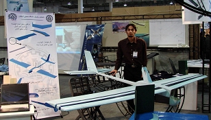
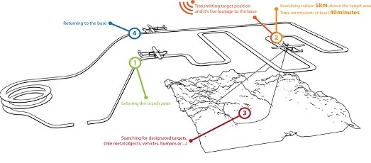
Homa Sazan (University Level) Missions and Goals:
1-Level 1 (2010-2011)
In this competition, participants must provide a UAV equipped with a Camera to search a 10 square kilometer area for at least 40 minutes to find 3 square meter marks on the ground with different English letters on them. Finding ground targets and reporting the geo location are criterion for choosing the contest winner.
 No guts no glory though!
http://www.suasnews.com/2011/09/8080/iranian-national-uav-competition/
I found this video over the weekend. Not sure if its been posted on here before but its worth the watch. Some pretty tight flying through jungles and bridges.
I made nice progress - but not after having some bad experience.
As you may know I decided recently to replace DCM with the solution from Seb.
During my holidays in holland i got a terrible cold but i could work a little bit.
Not in terms of a total new framework but experience what to do and not.
I started to change the pid control loop using this guide: The balance filter
The biggest surprise was the amount of propellors used.
One hand is enough for counting :-)
Above a simple hovering in the garage.
and the same outside.
To me the result is ok.
I am happy to have something flyable in a short time frame.
Hi everyone,
For years now we use model aircrafts as a hobby or job, and for many years as aerial platforms for aerial photography and mapping. So after many discussions here and reading, I will begin here an UAV application that I think and prepare from student and I hope that now I have the background to make it happen. The reason I post the project here is because I learned all about model aircraft from aeromodelling.gr and everything I know for autopilots from diydrones.com
I began my first efforts for knowledge and hobby with the famous Telemachus (similar to telemasters). The Telemasters are well known to most of you and they have been used as such platforms, although satisfactory results have pluses and minuses that we saw in corresponding topics. So after studying, planning and design of many commercial and non-commercial UAV’s, i resulted in the formation of one new platform that meets ALL of my conditions:
Finally anything else you suggest...
And we begin:
 Uploaded with ImageShack.us
2. Equipment detail
3. fuselage,
After much thought for the space, size, versatility, the total weight, I decided to give to my plane a “Stick” form, ie a square carbon fiber of 1,5cm witch all equipment, (wings, rudders etc) will be screwed on it and can change position depending on the setup and CG. The aerodynamic "outfit" will be left out as a surprise at the end of construction, the only hint is that the total weight of the planking will not exceed for 1 meter aircraft 60gr and it will be practically unbreakable!
4. horizontal and vertical stabs are in shape and size same with those of the skywalker, but is made of balsa & depron (6mm) with normal layout (not T-Tail) and the servos are mounted on them
Everything is screwed! Because a. I do not want even traces of glue, and b. the weight. Also I will be literally be able to unscrew everything and put it in a Bag.
5. Finally, all data from the cameras (dual 640 * 480 3d, RG NIR) will united directly to the base station in a GIS environment, ArcGIS, there the data will be fed into an algorithm that can calculate the terrain, the sunshine and hence the potential evapotranspiration (pennman), various health indices (NDVI, RVI, etc.), leading to immediate conclusions about the course of cultivation.

A little backround,
I am from Athens- Greece, I work as GIS technician for cadastral agencies and forest mapping cartography, I studied agriculture technology and environment management. The whole project has to do with my phd witch I hope to combine spatial data, agriculture techniks and knowledge with remote sensing and the calculation capabilities of GIS.
I purchased a full ardupilot mega kit from udrones ready and tested, I used it to fly right out of the box my custom made telemaster (img below)with perfect results, but I needed something more, so I am building my own airframe, I update my APM’s firmware and now I need some help to make it come to life.

I hope that are many people in this forum that we share the same interests (and passions) and I believe this could be a nice post-think tank to gather all opinions for remote sensing applications. Also I am willing to help everyone who wants to know more about photogrametry and GIS issues, image rectification and so on.
At this point I have to thanks, my employer Silva- Natura , www.greekwings.gr for providing cnc machinery and knowledge for the wing construction and www.nemhobby.com for sponsoring most of my rc gear.

Thanks in advance,
James Stefanakis
Great Idea for FPV, Onboard Camera and LCD on Transmitter Available in just 82$. The product comes in metal case.
This product is available at http://yingkemodel.en.alibaba.com/
Having a problem with your APM? No worries! I'll hop on the next plane and personally come check out your board, wherever you are. It's the least we can do.
For example, John Stuart was having trouble with his ArduCopter. As it happens, he lives in Cape Town, South Africa, which is a bit far from San Francisco. Not a problem! 24 hours of air travel later, and here we are this afternoon checking out the hardware near his house. And now it's working great!
Seriously, I just happened to be in South Africa with my wife on a speaking tour and we figured out we'd be just minutes from John's home, so we managed to meet up. He's got the coolest collection of multicopters I've ever seen. Mikrokopters, Droidworx and a couple ArduCopters, plus a bunch of planes getting ready to go. Plus he lives in one of the most beautiful places in the world in which to fly (the wine country outside of Cape Town). Thanks for the hospitality, John!
It's always great fun to meet up with DIY Drones members in the real world. We're looking forward to scheduling a meetup in London next month, too.
Today I maiden my wooden hobbyking Quadcopter and it went fine!
I have flown rc helicopters quite a bit, but that was a couple of years ago. Then i heard an interview with Chris Anderson on Leo Laportes podcast 'Triangulation' and I was intrigued about the drone part of the hobby.
Me and a friend ordererd two ArduPilots and got into it again.
Part list, I went for the 'el cheapo' line:
Model: HobbyKing Quadcopter Frame V1
Radio: HobbyKing HK6DF 2.4Ghz FHSS 6Ch Tx & Rx
4 ESC: Hobbyking SS Series 18-20A ESC
4 Motors: FC 28-22 Brushless Outrunner 1200kv
Prop: 8X4R Propellers (Standard and Counter Rotating), have 9x5 Propellers as well
Battery: ZIPPY Flightmax 2650mAh 3S1P 20C. To small, but it fits in the quad
Weight: 800 gram / 28 oz / 1.76 lb
Greetings from Anders, Sweden
Awhile back, I posted that my ArduPilot Mega (now Arduplane) gave me some headaches (also here). I loaded the previous versions of the code and went through the radio calibration and the setting of the hardware through the APM Mission Planner. But when I switch to Stabilize mode, the motor would start at full throttle and the servos would lock. I believe that the PWM of my radio at that channel (Stabilize) is not enough to trigger it. I believe the mode was not Stabilize but something else (FBW A maybe?) Anyway, I came back from an out of town trip and sat down with my Arduplane again. This time, I uploaded the newest version, 2.24+ Remzibi (for OSD) through the newest version of the mission planner. I underwent the same radio calibration and hardware settings. Success! Now the stabilize works. I have no way of testing whether the RTL worked but there's just one way to find out: fly it! I have taken some vids to prove it. Now the results are in: the newest version of the code works and have solve my problems.
Thank you Chris for your patience to help me. Thanks too, to the others who pitched in to help and advise. To the developers of the code and Mission Planner: Doug, Jordi, HappyKillmore, and the others I failed to mention, Thank you very much! This is why the DIY Drones community thrives.
Gent
I'm constantly loading and testing code and the power setup of the 2560 can be a bit of a pain. Mainly, the radio does not receive power because the Servo rails are only powered via a Lipo, which can be very dangerous. I never do anything but fly with a Lipo connected and I certainly don't connect one indoors. I'm just paranoid that way.
This hack will power the radio half of the servo rail with 5V from the APM's USB connection. The idea is to spilt the 5V rail into two halves. If you use an X-Acto knife you can easily cut the trace connecting both sides. I cut the ground rail in half as well, then used some solder to repair the bridge. Then I connected the 5v from the APM to the input side as indicated below. Now I can power the radio with the USB.
I've heard some people mention using bluetooth to communicate with microcontrollers as replacement for a serial or USB & FTDI. Recently some small bluetooth serial modules have become available from large electronics retailers and smaller ones that operate on large internet auction websites. They can be purchased now for just a few bucks. The module has all the bluetooth components integrated and takes 3 volt TTL level RS232 signals. It comes in a surface mountable pcb package, however breakout boards are available that have easily hand solderable headers, and a 3V regulator etc:
Although these modules are 3V, they will work with the 5V APM, so long as there is at least a 1K resistor on the RXD (which is what the 5V TX line on the APM will drive). The 3V signal from the module to the APM is OK as it is.
Starting communication is a matter of pairing with the device which comes up as 'linvor', then enter the default pin (0000). Add a com port to the device - mine comes up as COM8. The baud rate is 9600 by default, but can be changed with a special AT command, I set mine to 57600.
The range is nowhere near the XBees of course, however it is useful to configure PIDS in the back yard etc - it's also nice and cheap.
There is some information in a multiwii discussion here. Also an interesting page with some useful technical info here.
Hi guys,
Here I want to show you my new autopilot hardware which I worked on the past weeks.
The layout and the connections of the boards are chosen for my own convenience.
So airspeed sensor, receiver input, GPS, LEDs and I2C connections are at the front of the autopilot.
Servo output, serial ports, ADC and open drain outputs are at the back.
I also belief in the modularity, having two boards it is easy to replace the main board in the future when I need more performance and using the "expensive" IMU board again. It's still a small system with a height of 12mm and board dimensions of 62mm x 40mm, the weight is 35grams (mainly due to the stiff 1.6mm thick boards).
It's almost APM code compatible, only difference is the gyro+acc. sensor connected directly via SPI and the airspeed sensor which is connected to I2C via a one channel 16bit ADC.
It has all sensor "needed" on the IMU board, which are:
Compass: HMC5883L
3 axis Gyro+Acc.: SD746 (or MPU6000 if it is coming available and prove to be better that the SD746)
Baro: BMP085
Airspeed: MPXV7002 (via ADS1100 16bit ADC)
Three open drain outputs
Three ADC inputs
Three Serial ports
I2C port (5volt)
GPS (Serial port, EM406 pinout)
Status LEDs
Main board:
ATmega2560
ATmega328
TRACO regulator (max 36 volt input to 5volt output)
Eight channel receiver input at the front of the board
Ten channel servo output at the back of the board
Below are some picture of my work, now I have to test and do......some more testing :-)
Please let me know what you think of this solution......
Wish you all the best,
Alexander

