All Posts (14048)

Sort by

DEMO REEL, MORE MARCY1 DESIGNS


There's 1 big demo reel, containing highlights from the last 4 years.
Not nearly everything, but we got tired of editing.


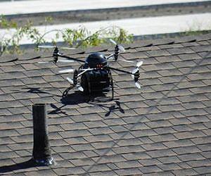
In the process of researching the demo reel, found this oldie but goodie from 2007.

It was a 2 way data connection, using the
audio channel on a 2.4Ghz TV transmitter + a 72Mhz RC transmitter. We
already had this gear & didn't want to invest $80 in radio modems, so
spent most of that year on this problem. After making it work perfectly,
inside, it completely failed outside, so we spent the $80 anyways.


MARCY 1 FLIGHTS


A very short break in the weather allowed us to make some progress on Marcy 1 airframes.


2 years of studying monocopters has shown that no-one really knows how
they work.  Our most stable design spins at 300rpm, a wicked low speed,
has a huge coning angle, has wing pressure at the CG, & has a winglet.

Shrink the wing diameter & it gets unstable.  Reduce the RPM & it gets
unstable.

3689407738?profile=original
Decent one. 12 minutes of flight time on a dead battery. Balanced
wing pressure. CG in the lighest area. Horrible coning angle.

3689408020?profile=original

3689408059?profile=original

Most stable configuration ever. Flight time of 11 minutes on a dead battery. Very low RPM & very little oscillation. The winglet is the key.

3689408041?profile=original

When this comes floating down from the direction of your aircraft, it's
going to be one of those days. Definitely pushing the limits of
structural margins. She didn't get very far without it. Surprised how
important it is for stability.

3689408104?profile=original

Wind was howling for this one. Got a lot of oscillation when applying
cyclic, but it settled after releasing cyclic. Needs to be repaired
after every landing.  Coning angle may indeed have a limit, with
increased lift only being available from the inner diameter.

3689408125?profile=original

Weather closed off again, by the time this was built.  Got a few flights in, between wind gusts.  It didn't have any more landing damage & it seemed to be the most stable.  RPM was down to the 250 range.  Definitely getting to where weight is above optimum.


SPECULATION


Tying 3 monocopters together to make a super long duration VTOL has intrigued us.  It would need 3 batteries.  Motors that size are super expensive.  1 radio beacon would contain throttle for the 3
rotors, but they'd have to take turns broadcasting return packets with telemetry.


Then there's the issue of torque with 3 monocopters.  They don't make
enough torque to turn a quad rotor.  You'd need a big, heavy servo.

Also looked at coanda effect copters for Marcy 2.


Looking over coanda effect copters, people are obviously more interested
in the flying saucer shape than the efficiency.  We've been wondering if
3 couldn't be used to make a tri rotor more efficient.

Coanda saucers never made sense, because they use airflow from 1 surface
of the aircraft to pull up another surface, like a fishing pole pulling
itself up.  They deflect air horizontally & then deflect it vertically
again.  The extra lift is supposed to come from the propeller exhaust
inducing a flow in the ambient air.

They also need 1 more servo than a lift fan, to control yaw.


Read more…
T3

Hi all,

looks that with the spread of processing methods and technology,

we can make things that were available only to national security agencies, once upon a time.

Take a look at the maps of the flight made May 18th:

one day to fly, one day to upload, one day for processing, (one day for grill party), one day to download.

3689407926?profile=original

3689407947?profile=original

Few of you might remember the 3km long flight with EasyStar (a single line), stitched with Microsoft ICE.

The map above is 2.2x2.2km. It took 746 photos to make this map.

Funny fact: if the aircraft would fly straight, the surface covered would be >16km2 instead of just 4.5km2 (null side overlap).

The overlap used was 70% side, 80% along.

Read more…

3689407885?profile=original

I recently received my Ardupilot mega, but I could not find instructions on how to get it working on airframes like Twinstar, which have separate servos for each aileron. One related blog post here in diydrones mentioned, that feature is being implemented (although I did not find an open issue about it) but I was too impatient to wait for proper fix.


Here's my ugly fix for this:

1. Disable aileron mixing from transmitter and make connections to ardupilot as you would do on 1-servo aileron case.

2. Connect 2nd aileron servo to ardupilot output 5

3. Open ardupilot sketch in arduino ide and open "Attitude" file

4. Insert these two lines to place marked in picture:


g.rc_5.radio_out = g.channel_roll.radio_max.get() + ( -1 * (g.channel_roll.radio_out - g.channel_roll.radio_min.get()));       
APM_RC.OutputCh(CH_5, g.rc_5.radio_out); // send to Servos


5. Compile and upload


Remove "-1 *" part, if 2nd servo does not need to be reversed compared to 1st servo.


Note!

Since failsafe mux only operates on first four channels, on event of failure, 2nd aileron can't be moved.


I hope this feature will be implemented properly in the near future, but this should do at least for now and at least for me. Hope this helps others too!


Read more…
3D Robotics

3689407842?profile=originalSpeaking of Chinese companies selling open source hardware for half price, Multicopter News reports that HobbyKing is preparing to sell the popular KK multicopter controller board for as little as $50. Note that this is just a RC controller board, not a UAV autopilot, but it's excellent by all accounts and IMHO this wide and inexpensive availability is great news for the community (although note below that they may not have made the best hardware choice on the microprocessor).


The price (based on the facebook page comments) is to be under $50USD , under half the price the KKuk boards are currently selling for

They quote that they have spent alot of time testing and on QC…… interesting to note its using the older atmega 48 chip, which will limit its software options to the originals done by Kapteinkuk .KKuk Official Site which is a shame, as the Atmega 328/168 is the chip of choice, allowing bigger firmware code to be run, such as that done by Mike Barton XX Rc Groups Thread and also Minsoo Kim from KKmulticopter.kr which includes H6 and airplane configurations.

The KKuk board started here Original Thread on RCG

This will be interesting to watch, to see if it is a positive for the KKuk community, making hardware more affordable, or if it is a negative, as the programmers loose the incentive to improve their product

Read more…
3D Robotics


From the Google Earth blog:

When discussing the new Ovi Maps 3D a few days ago, one interesting point about their maps are how they are generated -- hundreds of aerial photographs, automatically converted to 3D.

It's apparently growing into a popular technique, as Pix4D is showing off some similar technologies.

In the article they mention using the Swinglet CAM as a great way to capture the imagery for uses like this. The "4D" part of the equation is time; you can view the progress of 3D buildings through time, assuming you've done enough captures of a particular area.

Read more…

Flight testing - Well, learning to fly

3689407823?profile=originalSince my last post here, I've been patiently waiting for HobbyKing to get more Turingy 9x radio systems in stock. Alas, they sold out of Mode 2 before I could get an order together with a friend at work, so I went for a mode 1 when he placed his order and laid plans to break out the tools and change things over.

However, after a short wait, the assorted kit we ordered arrived and I have now started flight training in a borrowed 4ch trainer like this one.

The weather over the last few days has been pretty much perfect for soaring and the training is going well; I've gone from piling the plain into the ground on launch, to actually being able to hold position reasonably well, turn downwind and back into the wind and use ailerons to correct from gusts. I even landed for the first time today (landed rather than crashed that is!)


Here's a pic of both planes prior to the flights. Mine is the one with black tape all over the nose.

However, all that is secondary... My APM has been waiting for its chance, and with the shipment from HobbyKing we finally got hold of an airframe that has space to spare for the second LiPo and the APM board. The last few components should be available from toolboxes or the local model shop (servo extension cables to connect to the APM) and we should be good to go. The only thing we need from that point forward is a Windows laptop for waypoint programming. Oh, and a camera system. And decent weather.

Read more…
3D Robotics

Who should be a beta tester?

3689407853?profile=originalWe love our beta testers. They help us find bugs, fix them and test all those variations of hardware and configuration that no single dev team could test themselves. Much of the sucess of APM, ArduCopter and all the other DIY Drones projects is due to a large and incredibly supportive group of beta testers.


But beta testing is not for everyone. The code is, by definition, unfinished and probably buggy. It changes by the day, and sometimes by the hour. The documentation may be lagging. And when things go wrong, you can lose your aircraft.


Here's who should consider being a beta tester:


--Experienced users

--People with well-tested hardware/airframes, so we can differentiate between hardware and software errors.

--People familiar with Arduino, so they can deal with code if need be.

--People with loads of patience who want to contribute to making something awesome.


Here's who should NOT consider being a beta tester:


--New users

--People with airframes and electronics that have not already been tested and flown on non-beta code

--People who don't want to geek out a bit with code

--People who just want to fly NOW

--People who don't want to risk their expensive equipment on experimental software.


We love both groups, but my advice to all of our users is to think carefully about which group you're most comfortable in.


APM 2 is out of beta, so this is not an issue there. But ArduCopter 2 was just launched in beta two weeks ago, and although it's improving at light speed, I'm concerned that new users are using the beta code without being prepared for what beta testing means and requires. It helps nobody when new users who have never set up their hardware before swamp the beta testing feedback process with basic setup issues. It's understandably frustrating for them and it's frustrating for the dev team, too.


So, if you don't fit the criteria for the first category above, please use the tried and true ArduPirates software for ArduCopter. It's very solid. Please only use the AC2 beta if you DO fit the first category above.


As always, you can get the latest status updates on the ArduCopter news page. When AC2 comes out of beta and is appropriate for everyone, we'll let you know there and here on DIY Drones.


Thanks!

Read more…

3689388164?profile=original

The AMA insurance liason, Ilona Maine, has identified model aircraft used in manufacturer demos and sponsored pilots to be commercial uses and not covered by AMA insurance.


"You asked if a noon-time flight demo for the purposes of promoting the future sales of a RC product constitutes a "commercial purpose" as it pertains to AMA’s insurance.
The Westchester liability policy has a specific exclusion for commercial enterprises and/or business pursuit for individual members.  The policy does not provide coverage for any business entity. Whether or not noon-time demo flights fit into the business pursuit is difficult to determine and there is no “one answer fits all” response. As with any other claim, final determination would be up to a claims adjuster/insurance company based on the specifics of each individual claim. The situation is obviously a bit more transparent when a major manufacturer holds a noon-time demo utilizing their own employees as the manufacturer's insurance would apply. Generally, when we receive inquiries regarding sponsored (non-employed) pilots doing demo flights for manufacturers/distributors, we advise that they should not rely on AMA coverage. We cannot guarantee that the policy would respond and we don't want anyone to be caught by surprise in case of an accident. "


Since they consider them commercial use does that not mean they need to follow the current FAA regulations for commercial sUAS like everyone else?

Shouldn't they have to get experimental CoAs like any other commercial sUAS user?


By allowing commercial activities , although not covering them with insurance, aren't they aiding and abetting criminals?

Read more…

Don't do this at home with other planes!  ;-)


In the first episode motor, rudder and tail servos are not yet installed.

Plane is home made, there is no ready kit available.

- Wingspan 150 cm
- Length 120 cm
- Empty weight without batteries 1.3 kg
- Maximum load with batteries is about 1.2 kg
- Maximum takeoff weight is about 2.5 kg
- Flight speed is about 50 km/h, maximum about 80 km/h
- Flight travel with one 2100 mAh battery is about 7 km, flight time is approximately 8 minutes.
- In plane there is space for 4 batteries, so flight time is more than 30 minutes
- Space for autopilot, batteries and payload is about 30 x 7 x 5 cm.
- Wing is made from EPP foam, it is made with CNC hot wire cutter
- Fuselage is made from EPP foam and PVC pipe or fishing rod
- Price of the plane frame without servos and motor is less than 100 euros
- Price of the plane with good servos, motor and wires, but without batteries and remote control is about 395 euros in Finland, in other countries much, much less...
- The building time is about 8 hours

Plane homepage in Finnish: http://sites.google.com/site/taigacam/

Read more…

Mode Switch Setup for Turnigy 9x

3689407577?profile=original


Mode switch setup for Turnigy 9x

First thanks to tiger in the ardupirates thread at RC Groups who not only supplied me the files to reflash my radio back to standard, but included a model in the eeprom file with the mixes already setup. I just had to tweak the numbers a little and write a story.


I am an AC2 user so there may be some APM differences I have missed.


Some things in this tute may be a little obvious as I have tried to aim this one at novices. I figure some of you more advanced users will have upgraded this radio to ER9x firmware.


We will be using the 3 position F. MODE switch and either the 2 position GEAR or THRO HOLD switch in this example to be able to get all six flight modes for the APM/AC2.

Ch6 from the receiver will be used to supply the APM board. We are aiming to get pulse widths of 1165, 1295, 1425, 1555, 1685, and 1815. Remember that 1815 will put APM into hardware manual because it uses the ch8 input, so you may as well assign manual mode to that position when you setup your chosen flight modes in CLI. AC2 uses the ch5 input for mode control, so you can choose whatever you like.


Use the PWM(AC2) or RADIO(APM)  test in CLI to read the pulse width numbers for ch5 on AC2 and ch8 on APM.The pulse-width readout is now conveniently located on the Radio Calibration page of the Planner. I have used a servo programmer here as it is convenient for photos. Remember the inputs are ch5 for AC2 or ch8 for APM. Don't confuse receiver outputs with APM inputs.


Please don't just blindly copy my values as your radio may produce different pulse widths. The Turnigy is not as accurate as my 12fg and the pulse values seem to vary slightly every time I cycle power. Hey, it's a $55 radio :)

Remember to use the MENU key to exit the menu you are editing. The EXIT key does not save changes, ask me how many times I kicked myself.


1. Clear any flight mode mixing you may already have.

2. Start with end points at +- 100 and subtrim 0 for ch5 and 6.

2a. Use the ch6 output from the receiver for the APM/AC2 mode selection. Ch5 from the receiver is left unconnected.

3. Go to the AUX-CH menu and set ch5 to either THRO HOLD or GEAR. Choose whichever you find most convenient to use in conjunction with the F. MODE switch, you can come back later and swap if you’re not happy with your choice. You can also assign switches/dials to any other channels now if you like, but do not assign anything to ch6.

3689407588?profile=original


4. Put the F. MODE switch in position 2 and THRO HOLD/GEAR switch to the rear.

Go to the PROG.MIX menu and then setup MIX1 to look like this. Adjust the DNRATE value to get a pulse of 1555.

3689407637?profile=original


5. Leave F. MODE in position 2 and move the THRO HOLD/GEAR switch forward.

Adjust the UPRATE value to get a pulse of 1425, then hit Menu to save and backup to the PROG.MIX screen.

3689407601?profile=original


6. Put the F. MODE switch in position N and THRO HOLD/GEAR switch to the rear.

Setup MIX2 to look like this. Adjust the DNRATE value to get a pulse of 1685.

3689407697?profile=original


7. Leave F. MODE in position N and move the THRO HOLD/GEAR switch forward.

Adjust the UPRATE value to get a pulse of 1295, then hit Menu to save and backup to the PROG.MIX screen.

3689407650?profile=original


8. Put the F. MODE switch in position 1 and THRO HOLD/GEAR switch to the rear.

Setup MIX3 to look like this. Adjust the DNRATE value to get a pulse of 1815.

3689407813?profile=original


9. Leave F. MODE in position 1 and move the THRO HOLD/GEAR switch forward.

Adjust the UPRATE value to get a pulse of 1165, then hit Menu to save and backup to the PROG.MIX screen.

3689407760?profile=original


10. That’s it. If you flick through all 6 combinations, it should be pretty close to what the APM/AC2 expects to see.  I ended up with  1165, 1297, 1425, 1555, 1683 and 1814.

If something has gone wrong, you probably hit the EXIT key to back out of a menu instead of the MENU key. Remember EXIT doesn't save, stupid firmware.

Read more…


Once in a while a need a new copter, this time it had to be a very small Y6 copter. It is meant for FPV flying, and that really works very good! It fits through really small holes, and it flies very precisely. It is my first Y6, and I am pretty much convinced by this concept. Ok, well, flight time is an issue.. I get 6:30 min with 1000mAh, but that is still reasonable for such an aerodynamic disaster.

bolt2.jpg?width=200

bolt5.jpg?width=200


bolt4.jpg?width=200

Some more pictures can be found here:
http://shrediquette.blogspot.com/p/shrediquette-bolt.html


Some data:
Max. dimension 21cm
Roxxy 1815/25
Airace propellers
"CCD-Killer" CMOS FPV camera
mGUIDE controller
Turnigy Plush 6A ESCs + I²C->PWM micro converters
3S 1000 mAh battery
274g icl. battery & FPV equipment

Read more…
Developer

AC2 2.0.6 Beta

Just letting you all know that a new version is up. You must use the new version of Michael's Tool to do the setup. The older tool won't work with this version. CLI usage through the Arduino serial window will always work.


Many bugs are squashed. PID reports correctly now for D terms. 

The new rate based nav is on by default, but please be careful with it. Keep that hand on the Mode switch! 

Frames are a compile time option in the AP_Config.h file. (or use the GUI tool)

Frame orientation (X or + ) is done with a CLI based setup menu. (or use the GUI tool)

Basic motor LEDs are enabled.

Logging should be better but let's try and narrow down on the Bad Logs bug.

Jason


Read more…

Excitng First ArduCopter Mega Mission!

I finally got up the courage to try a mission with 2.05. I set up a very simple mission - takoff to 10 meters, loiter time 60, land. All the coords were very close to each other so it should land about where it took off. The first two times I started the mission, it went up a few feet and then bounced around the ground like it was at altitude and loitering. The third time was very different - Up it went very high - seemed like more like 100' rather than 10 meters - and I was sweating bullets. It then loitered for what seemed like much more than 60 seconds, but I bit my lip and waited. It then began a landing pretty much on target, but at about 20 or 30 feet it decided to head towards a corner of the park and I aborted, though it might have landed OK if I had more room.My theory is that there may be probs in the altitude sonar/ baro switch. When I lock height, it bounces a lot if within sonar range, and sometimes just shoots up without stopping. I verified the sensors by loading Ardupirate code - unit is very accurate on sonar height with this code, so I know the hardware is OK.The landing way off target was puzzling. I let the GPS run for a while, but maybe coords changed. I wish I would have had more room to see where it ended at.I also assumed that mission end at 'land' stops the mission, but soon realized I had to kill mode switch as soon as it landed or it will repeat the mission. Might be nice to wait for a throttle toggle to start again.Anyone else seeing this?
Read more…

3689407484?profile=original


One area of multi-rotor UAV research that has been barely scratched is ground locomotion. The definition of ground locomotion is the use of systems built into the flight vehicle to move on the ground, likely without using the flight propulsive systems. Basically, this is what you get when you combine a UAV with a UGV. The following points illustrate the reasoning and need for such a system:


1) Electric Multi-rotor UAVs are only limited in flight duration by the battery capacity they carry. So, unless they exhibit some type of energy-harvesting behavior (mainly solar- or laser-powered flight), multi-rotor UAVs must land, usually sooner than later as compared to a fixed-wing UAV.

2) Although Multi-rotor UAVs are well suited to human-operated or human-assisted missions such as aerial photography, bridge inspection, and so on, there is little reason against, and many possibilities for, development of a completely autonomous system that does not require human supervision. This includes perimeter monitoring, migratory vehicles, scientific sampling, and other tasks. To create such a system, the vehicle must be able to autonomously recharge or exchange its batteries.

3) At present, most autonomous multi-rotor UAV research takes place in an indoor laboratory where researchers directly handle and maintain the test vehicle. Unless the research focus is the development of a recharging plate or platform for the test vehicle to land on to recharge (such as has been done at ETH Zurich), the autonomous system is only self-reliant in matters of flight and aerial maneuvering. Rendered another way: the machine must undergo the equivalent of a major surgical operation (preformed as the researcher removes and replaces the battery pack) in order to remain an active flying machine.

4) If the research topic is autonomous recharging, multicopters work great in an environment where a well-tuned motion-capture system and developed charging interface exists. However, as soon as autonomous multicopters venture outside of the lab into the outdoors, the well-defined and controlled environment disappears. Multi-rotors can exist in this type of environment just fine so long as attitude state information is known, but position information is somewhat reduced: The cues from a GPS and other navigation source can have a mean error of up to 2 meters, far to large for a precision landing on a charging pad.

5) A motion-capture system could be installed at the critical area of a landing pad or recharging dock/station to forward accurate position and state data to the vehicle. A multi-rotor could use GPS to arrive in the vicinity of the target area, to have the motion-capture system pickup the reflective patterns on the UAV, thus accomplishing the same precise interface as in the lab. Conversely, the UAV can have the vision-systems/devices necessary to use cues from defined targets on the landing dock.

6) For both versions of the solution posited in Point 5, there is still a large degree of complexity. Either the UAV must communicate with the ground station motion-capture systems, or the UAV must be able to identify specific marks on the charging platform. This ignores the other complex tasks involved in the scenario such as identifying if a station is already occupied by another quad/multi-rotor, and the possibility for unusual lighting and optical difficulties that might make vision-based landing difficult.

7) The alternate solution introduced here: At the cost of about 40 to 60 grams, a pair of continuous-rotation servos with wheels can be mounted to the underside of the quadrotor. Instead of negotiating with a motion-capture data link or processing data from a computer vision system to make a perfect landing on the charging pad, the entire flight vehicle can make a landing using GPS to within a flat 3 to 5 meter square target area. On the ground, the vehicle can drive directly to a empty charging dock using methods that have long existed for UGVs, such as line-following or lighthouse type arrangements. The control problem is simplified in that no motion capture system needs to exist, and the design of the landing area can be simplified or done away so long as the vehicle can drive in the landing area unhindered and locate a charger readily.

8) The utility of a ground locomotion system is much more useful to a multicopter than for just charging: Positioning on the top of a building for a better camera shot, handling the logistics of entering and exiting structures and areas that subdue flight devices, and accomplishing movement in general without using the flight devices are just a few examples.


3689407292?profile=original3689407605?profile=original


Bibliography and Related Work:

VTOL Air/Ground Design: http://diydrones.com/profiles/blogs/transformer-bot-turns-from

ETH Zurich Recharging Pads: http://youtu.be/pcgvWhu8Arc (Seen from beginning and 0:25)

Attempts to have a multi-copter land on a UGV: https://www.youtube.com/watch?v=XpUdW_U2KJ8

Ground-based recharging: Seen in all commercial household cleaning robots such as the iRobot and Neato.


Read more…

Remzibi OSD + APM Integration v2.1.2


1/ Software Update on the integration of Remzibi OSD and APM

I am just updating Blake's and binzi's Blog contents:  Blake and binzi

I do not know how to make a firmware for APM Planner, so you will need to use Arduino GUI tool


Replace your ArduPilotMega folder with the ArduPilotMega folder from APM2.1.2-OSD.zip:  APM2.1.2-OSD.zip


Configure the APM_Config.h to your need

//to deactivate use OSD_PROTOCOL_NONE
//#define OSD_PROTOCOL OSD_PROTOCOL_NONE
#define OSD_PROTOCOL        OSD_PROTOCOL_REMZIBI

// port 3 is the telem port on the shield
#define OSD_PORT            3

// set a radio switch to activate/deactivate the OSD output :

// below 1450 will display the OSD

// above 1450 will stop displaying the OSD

#define OSD_MODE_CHANNEL    6

// choose your unit to display the disctance to waypoint in feet or meter
#define OSD_UNIT            OSD_UNIT_METER
//#define OSD_UNIT            OSD_UNIT_FEET

Then follow the normal process from the wiki above.

http://code.google.com/p/ardupilot-mega/wiki/Code


2/ Hardware

To connect your APM with the Remzibi OSD, you need to have a cable from Telem port to Remzibi GPS port. GND and TX (from APM) are enough.

If you do not see any OSD info at first, stop your camera feed to see if the OSD shows up anything. You might be starting in the wrong TV mode (PAL/NTSC). You just have to push the OSD button for about 1 second.


3/ Remzibi

You need to use Remzibi OSD software from Remzibi site and update your layout with APM.bin and flash the firmware using ARDU firmware (Announcement) in the same software.

Note: for metric or feet units , be carefull to use the right unit in the Remzibi OSD software. You need to change the APM_Config.h for feet/meter of the next waypoint in the status at the bottom


4/Usage

Once everything is connected, normally the APM sets HOME for the OSD once it gets a GPS_fix. If you connected your OSD after that, then you can just push the OSD button once to force the HOME location on the OSD.

The arrow and distance from home will always display home direction and distance to home direction. It won't show the next waypoint direction (too complicated yet )


5/ what's new

I have updated all the units and it should be displaying proper values now


Read more…

New Commercial Quad-Copter Available

tialinx-phoenix50-h-uav-lg.jpg

TiaLinx has announced the launch of the Phoenix50-H. The quad coaxial mini-copter system is capable of performing multiple functions such as detecting movement or breathing of a hiding person in a compound from a sloped roof. The mini-copter can be remotely controlled at extended standoff distances of more than multiples of 100 feet from ground or an airborne asset to keep the operators out of harm's way.The lightweight and agile mini-copter with programmability to fly to or land at multiple waypoints has been integrated with TiaLinx's fine beam ultra-wideband (UWB), multi-Gigahertz radio frequency (RF) sensor array.An onboard microphone and video camera augment the sensor capability of Phoenix50-H. TiaLinx's advanced real-time and light weight UWB RF imaging system was an essential step in the development of Phoenix50-H to operate at high elevations for prolonged missions. The transmitted power of the UWB signal is less than a typical cellular phone.Read all about it in Space War online.
Read more…

3689406838?profile=originalHi guys this is another late night post but I'll try to lay it out right.

I have updated the:

  • Camera tracking code to use the new DCM maths
  • Camera control code to use the APM_RC stuff instead of the outdated servo_out (ashame to be honest as that was very easy to use but the new one is more accurate).
  • Waypoint activity sketch to work with the new location variables (thats the only change but it make the code look harder than it is).


Thanks to Mr Doug Weibel my fears of complexity have been allayed and everything needed to get this going is in one config file. . As I have received interest I am releasing this before I have flight tested under the new APM2.1 release. My previous blog posts show my old camera setup with retraction and targeting but I now have a GoPro so its back to the drawing board.


Camera Sketch Download v1.10 (whenever I edit the file I'll increment - thanks to those wanting more)

Extract the zip file inside your APM2.1 folder with the rest of the sketches, add #include "Camera_Config.h" at the end of the header includes section in the ArduPilotMega.pde, add the do_control_video case in the handles_must void of the commands_logic.pde, add the verify_do_control_video case in the verify_must void of the commands_logic.pde and overwrite test.pde (it has a test for the camera servos).

(Click the picture at the top for an animation for where - not sure why its not doing it always though guess ning isn't gif friendly).

The variables in the config are fully commented so you can change them as you need. This works with all servos of limited range (<360) and the tilt servo only move to vertical so the picture is always the right way up.

For setup of the variables use the comments next to the variables in the config as well as the picture below.


Updated:

  • Fixed codebase problems, Johann's check created, Euler angle incorrect units now fixed.
  • Added stabilisation (two lines and no mathsm stupid to leave it our really).
  • Added relay triggering method (thanks Kirill).
  • Two methods for waypoint triggering now coded.
  • Added two new triggering methods that should limit vibration.
  • Separated the voids used by APM (mavlink ones and test code).
  • Added test code for the camera servos (pan/pitch, tilt/roll and trigger not retraction).
  • Added PAN_RATIO and TILT_RATIO to variables to change movement of servos easier.
  • Alter test code to move in 15° steps around axis so checking of servo movement ratio can be done.
  • Created new targeting code that works with all limited movement servo (<360) fitted the the bottom or top of the plane.
  • Diagram on the maths for calculating the virtual co-ordinates

Waypoint Triggering - Do something at a waypoint.

  1. Waypoint triggering using the waypoint_check code you need to add waypoint_check(); to case 1 of the medium loop in ArdupilotMega.pde then change the values in waypoint_check to the waypoints you wish to take picture at.
  2. Mission planner to use waypoint triggering (far easier in the field) you need to add picture_time_check(); to case 1 of the medium loop in ArdupilotMega.pde then in the mission planner add do_control_video waypoint to start and stop taking photos at waypoints.

Camera Triggering - use camera

  1. servo_pic - wiggles the servo to press the camera button. You need to adjust the wiggle to press the button correctly without stalling the servo.
  2. throttle_pic - turns off the throttle, waits (time), uses servo_pic to use camera then turns throttle back on. The wait is derived from the # of cycles the medium loop sees (default = 10).
  3. distance_pic - turns off the throttle, waits (distance), uses servo_pic to use camera then turns throttle back on. The wait is controlled by the distance to the waypoint (default <3).

GPS Tracking - its only pointing at home still but with waypoint planning hopefully working this may be updated soon so it will actually be useful :) until then I wouldn't worry about it.

Currently grabs waypoint 0 (home) and tracks that.

Add GPS_track(); to the fast loop of the ArdupilotMega.pde just before the } at the end.


Stabilisation

Add cam_stabilisation(); to the fast loop of the ArdupilotMega.pde just before the } at the end. 


Testing your camera setup

With everything in your airframe and ready to test the connections to your servo setup and that you have configured it correctly use the test section of the CLI and use "camera". The test will:

  1. pan left to right in 15° increments
  2. pan right to left in 15° increments
  3. tilt up to down in 15° increments
  4. tilt down to up in 15° increments
  5. take a picture

To check angle increments use this picture around your servo. If the movement is less than 15° you need to increase the ratio value and if it is more you need to decrease the ratio value. If everything moves as it is supposed to well done you have configured the entire setup and are ready to use it on a flight.


I used the previous iteration (APM1.13) of this code happily but with the changes I may have borked it somehow. The config file can be changed by anyone and has details on what each variable means.

If you do not understand any of this do not use it. This is for those pushing the envelope.


Disclaimer: I have not flight tested this code yet, I nor DIYdrones take any responsibility for damage caused.

3689406680?profile=original3689406790?profile=original


Read more…

3689407389?profile=originalArdupilotMegaPlanner was written in .net which is a Microsoft language that they opened up the standards to. An opensource mutiplatform version of .net's CLR came out called mono. Ubuntu comes with mono installed so you can run ArdupilotMegaPlanner.exe without installing anything. All you have to do is open ArdupilotMegaPlanner.exe with mono and your golden.


Here are the steps I used to get ArdupilotMegaPlanner running. Right click on ArdupilotMegaPlanner.exe and select "properties" now check the the "permissions" are set to executable. Now click on the "open with" tab click on "add" a new window will pop up and on the bottom you'll see "use custom command" type "mono" (without the "") and hit the "add" button now double click on ArdupilotMegaPlanner.exe and you should be good to go. There are some glitches like the graph bars are sideways, the setup tool freezes and mavlink and pid adjuster only works through telemetry (which is fine by me because that is how I was wanting to use it any way), but the important functions like the firmware unloader, updates, and flight data work great!!


3689407403?profile=original


3689407424?profile=original

3689407315?profile=original


3689407452?profile=original


Oh ya it doesn't open a whole window just a menu bar that doesn't stand out at first. nothing is wrong it acts the same way in windows.


3689407336?profile=original


I would like to say thank you to Michael Oborne for writing the the program, making it open and available to all of us, and for writing it in a multi platform language that we all can use.


P.S. with mono installed Mac users should be able to use this program as will

Read more…