All Posts (11086)

Sort by

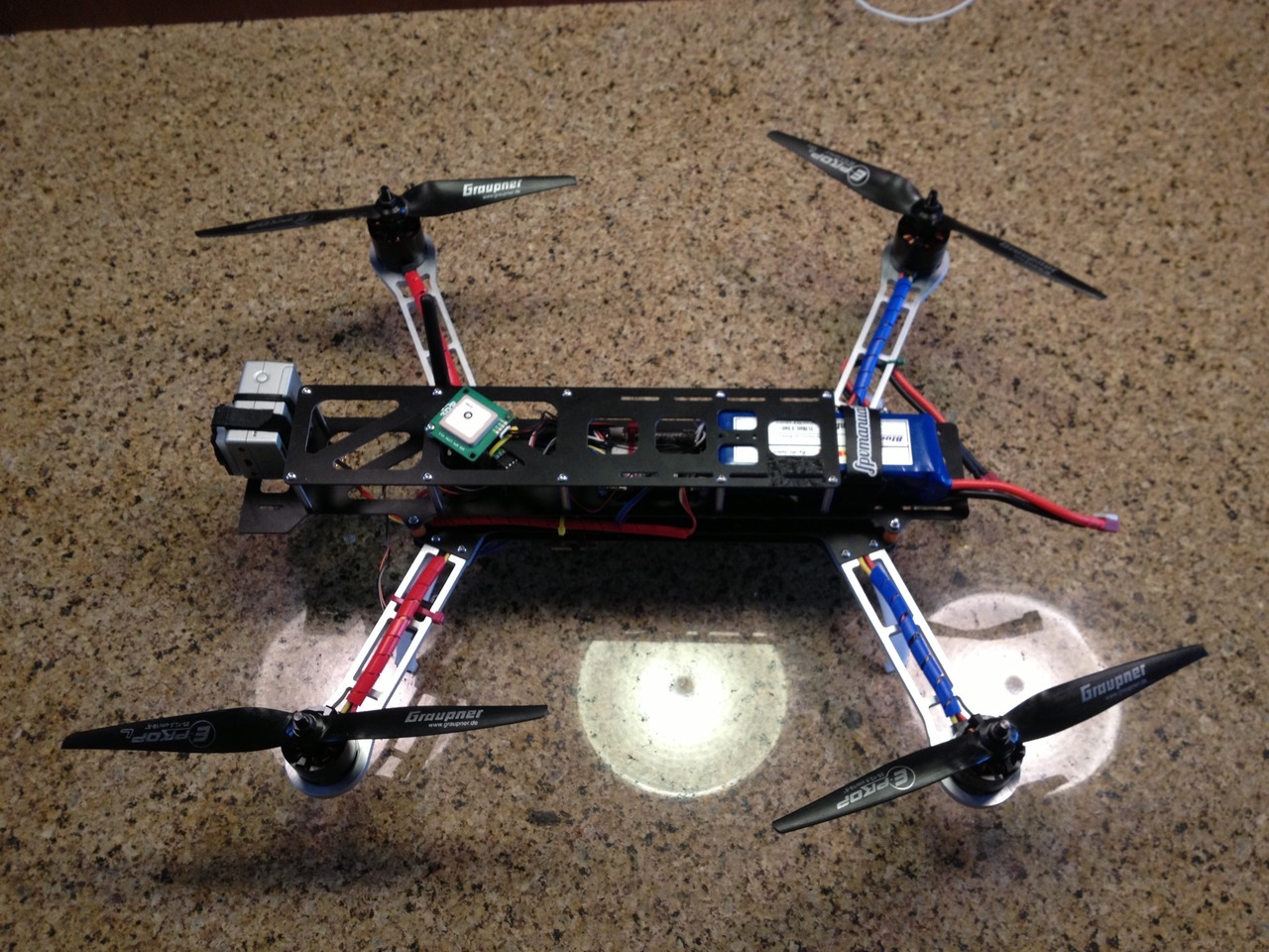
My QAV500 quad progress

tumblr_mdftqaJpP31rgpsuzo1_1280.jpg?width=640

I have been poking this build with a stick occasionally as I was working on my Power Wheels Rover project in the meantime. But now I am back to working on this quad.

Build list:

  • QAV500 frame
  • APM 2.5
  • SunnySky 2814-10 motors
  • Hobbymate 40A ESCs
  • Graupner E-Props 10x5

I have had a hard time getting this thing to play nice, and last night while reading more about ESC timing I realized that may have been my problem.  I was having occasional motor spurts, and sometimes one or two motors wouldn't spin up initially, they would pulse and behave strangely.  Early this morning I set the timing on the ESCs to low, and unsurprisingly it fixed the issues I was having.

I did a full config reset running 2.8.1, with motor size set for medium (0.110).  Flight is a LOT more stable than it has ever been, and had a slight breeze too.  All is left for me is to get more flight time, and practice, practice, practice!


More photos etc at: http://projectable.me/post/35643555854/more-tweaks-to-the-qav500-platform-i-moved-all

Read more…

Gimbal support on APM - dead easy

I wasn't sure what would be involved in getting a simple gimbal (in my case, just a tilt platform really) hooked up and working, but it was dead easy.

My wife recently made me a present of a GoPro Hero 2 and a tilt-mount.

3689486803?profile=original

This is a cheap little thing, but it fits the frame I have and it comes with the servo, and it was a gift - so you can't complain.

Took a look at the ArduCopter docs and was a touch intimidated, but as it turns out, it is really easy to get working. Once it was on the frame (took a little sanding and force), all I did was plug the servo into output 11 on the APM2.

3689486750?profile=original

If I had something that did roll as well as pitch, I would have plugged the roll servo into output 10 as well.

Where it gets really nice is that the Mission Planer has direct setting support for the gimbal now (as opposed ot what the docs say). I went to Mission Planner->Configuration->Camera Gimbal (duh).

On this screen, you can enable Tilt, Roll, and Pan individually, and can choose which channels to use for each. In my case, I enabled only Pitch, and set it to use "RC11" - this naming convention is a little confusing since RC indicates Radio, but it really is just the output pin number. I left the defaults for the limits. I chose Input channel "RC6" - which actually is a radio input channel.

I have channel 6 on my TX set to a pot for use in tuning, so I chose to use it here. Note - to use Channel 6 for the gimbal, you will want to make sure it is set to CH6_NONE in the ArdiCopter Config screen.

So in theory, channel 6 should set the angle of the mount and then the APM will maintain that angle to counter the pitch of the quad.

As soon as I picked up the quad, the gimbal worked. I could set the angle with the pot and it compensated for pitch as I tipped the quad back and forth. If only everything was this easy.

Once it stops raining in March next year, maybe I'll get to fly it. 

Read more…

Fundamentals of Small Unmanned Aircraft Flight

3689486493?profile=original

 Being involved in UAV research, I've been a member and a great admirer of this community for a number of years.  An article I wrote (Fundamentals of Small Unmanned Aircraft Flight) has recently been published in my organization's Technical Digest and is freely available.  I am hoping that members of the DIY UAV community might benefit from this effort.


The article covers flight control methods as well as UAV state estimation methods (i.e. fusing sensors to estimate position and attitude).  Flight control algorithms are treated very generally, basically just describing simple PID control for different flight modes and channels.  For state estimation, the article covers Kalman Filter-based approaches as well as the Mahoney/Premerlani/Bizard "DCM" method that many in this community are familiar with.  (In the article, I refer to the "DCM" method as the AHRS Feedback Controller method, as it can also be described using quaternions or euler angles.)


Although the focus of the article is small fixed-wing UAVs, many of the methodologies described can be (and are) applied to other types and sizes of UAVs.  The flight control and state estimation methods described are not specific to any particular UAV, but I will admit that I leveraged resources from the open-source UAV community.  The article is freely available at the following link:

     www.jhuapl.edu/techdigest/TD/td3102/31_02-Barton.pdf


As a companion to the article, I also put together some heavily-commented MATLAB routines (called SUAS Code) implementing both the Kalman Filter and the "DCM" Feedback Controller state estimation methods.  (For the really interested user, the code shows how to implement the "DCM" Feedback Controller method using either Euler angles, quaternions, or Direction Cosine Matrices.)  A link to the code can be accessed through the MATLAB Central Link Exchange:

     www.mathworks.com/matlabcentral/linkexchange/links/3474

(The Link Exchange provides a link to the actual SUAS Code website.  Please forgive me that this a "link to a link", but the MATLAB Link Exchange counts "clicks", giving me feedback as to whether anyone is finding it useful.  Also, please be forewarned that you will have to OK an End-User-License-Agreement before downloading the code.  It is intended that the code be freely available for academic, personal education, and research purposes.  The EULA really just restricts commercial efforts, so hopefully no one in this community will find it too distasteful.)


Again, I am hoping that the paper and code are of benefit to this community.


Read more…

DebugSetVariableRunningExample2.png?width=750

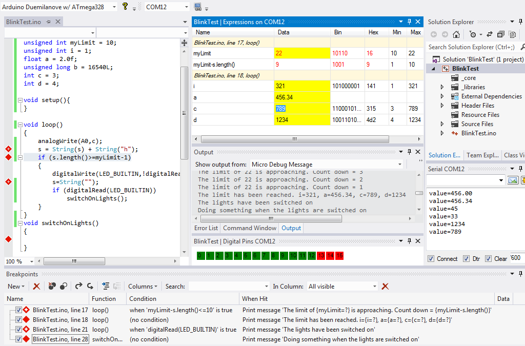
In May 2012 a unique serial debugger for Arduino was released in beta and has recently been updated to include the ability to change the values of variables while an Arduino is running.

In the image above you can see the entire code of a very crude (rubbish) Arduino program that is running a debugging session. You can see that the trace messages and variable values are different to those defined within the compiled program.

Approximately 300 people have joined the beta program. Feed back has been really great.

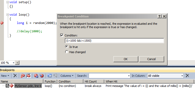
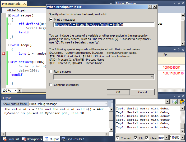
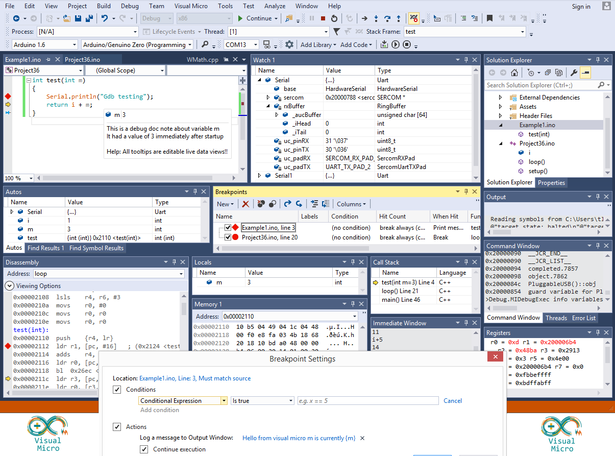
The debugger integrates seamlessly into the Visual Studio IDE providing conditional breakpoint, trace and expression watch features. Unlike a conventional debugger, the Arduino is not required to break (pause) to enable variable values to be altered (optional).

We can use any available Arduino code to conditionally apply breakpoints.

image.axd?picture=2012%2f5%2fArduino+Visual+Studio+Break+Point+-+Condition+Dialog.png&width=750

Complex or simple debug messages can be generated without the need to include the text of the messages in the final Arduino program. For most users this prevents the programs from becoming "bloated" with text/debug messages

image.axd?picture=2012%2f5%2fArduino+Visual+Studio+BreakPause+F5+To+Continue.png&width=750

APM FastSerial is fully supported. Debug using xbee is also supported but you should not fly a debug version without first becoming very familiar with how the debugger works. (If you are unsure then talk it over with us in the Forum). The image below shows a running apm debug session that is sharing the main serial port with the apm code. This is optional, we can share or use any arduino serial port (in most cases) or use other Arduino technologies such as SoftwareSerial.

ArduPlaneFastSerialDebug.png?width=750

The Arduino debugger is currently being distributed for free to anyone who would like to join the beta program. You can join the program by registering for the Visual Micro forum and including a request for the debug tool.

If you don't have a copy of Visual Studio Professional this article explains how to get a 3 year licence for free.

If you do use the debugger for an apm project (or with an apm example) then you will find a few tips for configuring an apm debug session here

The debugger is an upgrade to the free Arduino plugin for Microsoft Visual Studio Professional. Further reading, small wiki and a YouTube example can be found at visualmicro.com

The debugger optionally supports open source visualizations allowing us to create graphical controls that represent the various sensors of our Arduino projects

VisualMicroDebuggerExtensionsVisualizations1_Small.png

Read more…

Distance measurement with Rigol


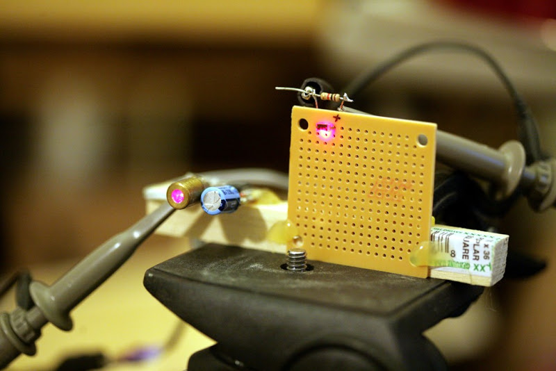
distance01.jpg
So ya wanna measure distance with 4 cheap radios & a cheap SRAM to measure propagation delay.  Before investing in a full system, let's try it with a laser reflection & a Rigol.

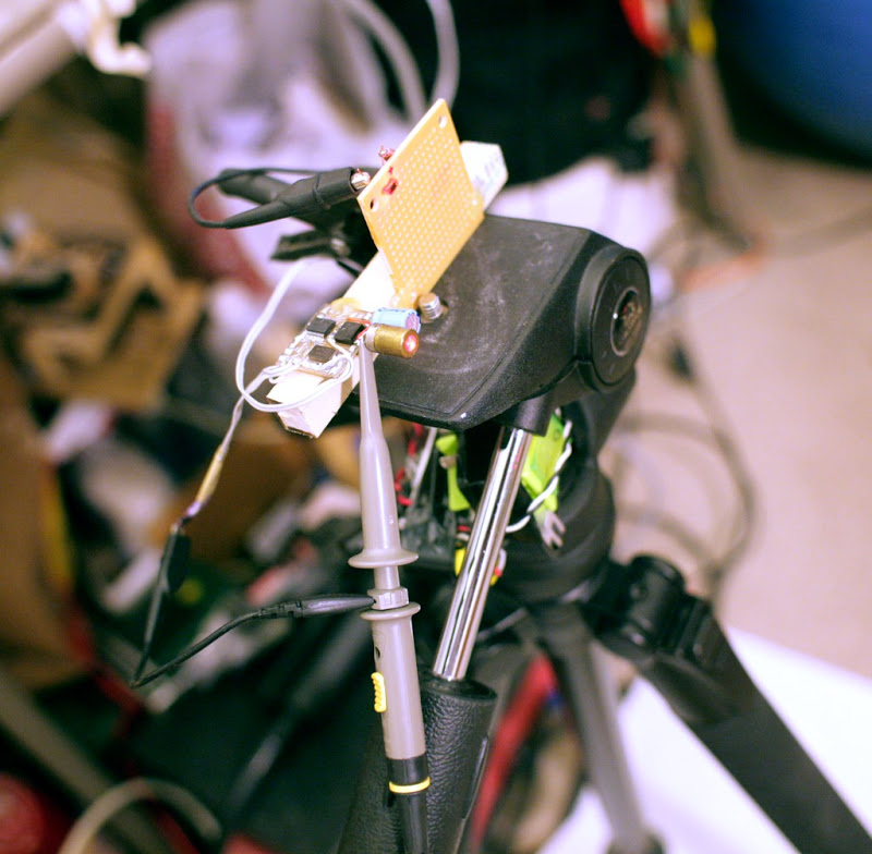
A laser diode is attached directly to a microcontroller pin via the shortest path possible.  It'll get 3.3V at 50% duty cycle, so it won't burn out while still delivering useful brightness.


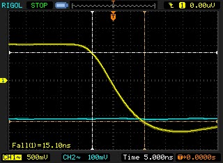
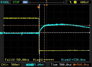
laser_rise_time.png


The laser rise time is given by the fall time on the cathode, which is extremely short.  There's no way to measure how long it takes to light up, in this apartment.


distance02.jpg

Next, we have a photodiode receiving reflected laser light from various distances.

distance03.jpg

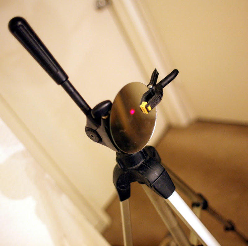
A very carefully, painfully aligned mirror reflects the laser.  Should have used the heavier tripod for this.

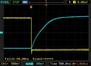
laser_reflection01.png

With the mirror 1ft away, the Rigol now becomes the Rigol of despair, as the rise time of the photodiode is nowhere close enough to the rise time of the laser to see a delay on the screen.

What if you take the 1/2 way points of the 2 rises?  That would get it to maybe 100ns, a distance of 30 meters.

laser_reflection02.png

With the laser moved 15ft away, now the rise time of the photodiode is 4 times longer than before.  It has too much capacitance, causing the half way point to be more correlated with signal strength than propagation delay.


distance04.jpg

Maybe a very low resistance pulling down the photodiode & a very high amplification would get rid of enough capacitance.

laser_reflection03.bmp

The mighty capacitance fighting resistor did get the rise time down to a more useful range at 15ft, but still very erratic.  There still might be useful data with extreme averaging & the higher quality amplifier in a radio.

laser_reflection04.bmp

At 1ft, there's no obvious change in propagation delay with the noise. 


A cheap radio would have automatic gain control & might have less capacitance, but the problems of longer rise time with a smaller signal & erratic half way point in the waveform would probably still be too great.

Another idea was to hack a laser tape measure to use a radio for part of the signal propagation. The same problems of capacitance & erratic rise time would apply.

The kind of components it would take to measure propagation delay of RF are going to be out of reach for a reasonable cost.  You'd think someone would invent a local area GPS system, which used a different frequency, but used the same components to have a cheap GPS system in a room.

Over the years, the ability to detect a 1/115200 second time difference with a simple chip radio has led to the idea of measuring distance with low cost components. A pair of radios operating on different frequencies & hard wired so 1 directly transmitted the voltage received by the other could theoretically allow the propagation time of a voltage change to & from the aircraft to be measured. It would use a bank of staggered comparators, all timed by a slower clock, to detect very small differences in time.

10 staggered comparators timed at 100Mhz resolution would have 30cm accuracy. Averaging hundreds of samples might get it down to 3cm. It really depends on how noisy the signal is. Rough knowledge of RF communication says the lower the bandwidth, the less precisely the arrival time of a signal should be known. If it has 256kbit of bandwidth, the arrival time should only be known to 1/256000 seconds. But GPS has only 1megabit of bandwidth, so that shouldn't be a problem.

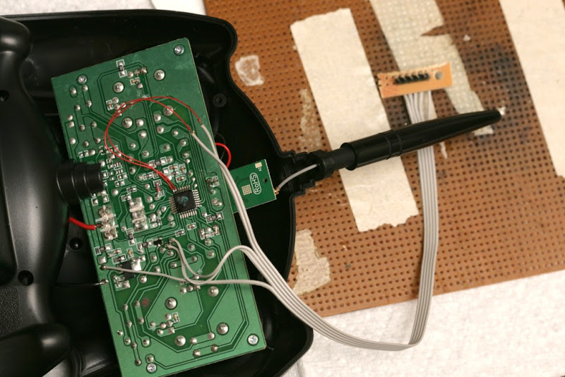
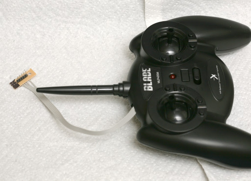
The Rigol & a set of 4 radios could do a simple proof of concept, up to 3 meter accuracy.


blade14.jpg

blade15.jpg

Anyways, the schedule is now to convert 1 new aircraft to autopilot every month, combined with several days of formalities required to run a business: meetings & traveling.  It's extremely ambitious & doesn't leave any time for experimenting.
Read more…
3D Robotics

3689486618?profile=originalI mentioned a few weeks ago that Stephen Wolfram (Mathematica genius) and his 13-year-old son Christopher presented after us at Maker Faire NYC this year, and Christopher did a very impressive AR.Drone demo (with even more impressive on-stage debugging). Now Stephen hasposted with more info about that:

Christopher has been an avid Mathematica user for years now. And he likes hooking Mathematica up to interesting devices—with two recent favorites being Arduino boards and quadricopter drones.

And so it was that last Sunday I walked onto a stage with him in front of a standing-room-only crowd of a little over 300 people, carrying a quadricopter. (I wasn’t trusted with the Arduino board.)

Christopher had told me that I shouldn’t talk too long—and that then I should hand over to him. He’d been working on his demo the night before, and earlier that morning. I suggested he should practice what he was going to say, but he’d have none of that. Instead, up to the last minute, he spent his time cleaning up code for the demo.

I must have given thousands of talks in my life, but the whole situation made me quite nervous. Would the Arduino board work? Would the quadricopter fly? What would Christopher do if it didn’t?

I don’t think my talk was particularly good. But then Christopher bounced onto the stage, and soon was typing raw Mathematica code in front of everyone—with me now safely off on the side (where I snapped this picture):

Christopher Wolfram on stage at Maker Faire

His demo was pretty neat. He had a potentiometer hooked up on the Arduino board. And he’d set it up so that all he had to do was type a command intoMathematica to get its value:

ArduinoAnalogRead[0]

357

Then it was Dynamic[ArduinoAnalogRead[0]], and Mathematica is dynamically displaying the value in real time as he adjusted the potentiometer.

Then he makes it into a gauge (er, that’s actually from a future version ofMathematica, but Christopher is a keen user of internal development builds):

Dynamic[AngularGuage[ArduinoAnalogRead[0], {0, 1023}], UpdateInterval -> 0]

Gauge dynamically displaying the value

And then he says he’s going to make a dynamic plot of it. And pretty soon he’s typing the Mathematica program, confidently presses Shift-Return—and it actually works:

data = {}; Dynamic[rawdata = ArduinoAnalogRead[0]; AppendTo[data, rawdata]; ListLinePlot[data,Filling -> Axis, ImageSize -> 500], UpdateInterval -> 0]

Plot of potentiometer data

Then he’s on to using an ultrasound sensor, and having it produce musical notes based on distance.

And then he’s on to the quadricopter. He’d been going back and forth with someone at our company for a few days before, trying to get the kinks out of the interaction with the quadricopter‘s API. I had seen the quadricopter fly that morning, but I knew Christopher had changed the code quite a bit since then.

His plan was to have a single line of Mathematica code that would make the quadricopter fly a specified 3D path. He had a list of points for a square, entered the line of code, and pressed Shift-Return, and… nothing happened!

I guess Christopher has debugged quite a lot of code in his 13 years. And now he set about doing it in front of the audience. A missing function definition. A missing command to connect to the device. He was finding quite a few things. And I was getting ready to call out that he should just give up.

But then… the sound of quadricopter blades, and up the quadricopter goes… flying its loop on the stage, and landing.

It had actually worked! It was pretty neat, being able to just type one line of code into Mathematica, and then having some physical object fly around in the pattern one had specified:

ARDroneFlyPathGraphics[Table{Sin[u], Sin[2u], {u, 0, 2π, π/5}]]

Path for the quadricopter

After another flight, the audience had questions. One person asked if the quadricopter could respond to its environment. Which set Christopher off on some more “spectator programming”. And actually, it took him only a line of code to get the real-time video from the flying quadricopter, and feed it through simple Mathematica image processing:

Christopher Wolfram on stage with the quadricopter flying

I was pretty impressed that all this worked (here is the full video). And, yes, Christopher was clearly right that his topics were very relevant to Maker Faire. In fact, it seemed like Arduino and quadricopters were two of the three main technical themes of the show. The third was 3D printing.

Read more…
Moderator

BFRO Gets UAS Support for Squatchin


Ok, so Big Footing is not exactly "Main Stream", but IMO, this is a great example of how we can enjoy our hobby while helping others explore theirs.  Unfortunately, there's not a lot of details on the drone or UAS Operations but  it's a positive example none the less.  I live in Northern California, and want to take my drones on a BFRO expedition...

Read more…
3D Robotics

This one is called, er, the "Bad Ass HoverWASP RC Quadcopter". It's created by a team who call themselves "Two Silicon Valley Engineers" but seem to actually live in Reno, Nevada ;-) They want $1050 for the GPS version (for hold and RTL only) of their quad, although it does come with a GoPro camera and some kind of RC gear (looks like the $59 Turnigy). Doesn't appear to be open source. At the moment, they have six backers.

From the listing:

Our prototype is a quadcopter that took over seven months to develop the proprietary algorithm for stability. This drone has four propellers that requires a special software code to maintain stability while flying. This is especially important if you do any videotaping to avoid a “jello” effect. 

We will have a "ready to fly" out of the box quadcopter. Most airplane and helicopter drones all require a technical assembly process that can be difficult and tedious such as programming your radio transmitter and your flight controller along with wiring and soldering. Our “ready to fly” out of the box drone is so simple that you can let your child fly it. 

We have partnered with a manufacturer to build all the parts to our quadcopter and we will assemble the final product in the United States. But to manufacture the parts and assemble it we need your help. The crowd funding from Kickstarter Backers will allow us to go from beta-prototype into final production. 

Read more…
3D Robotics

"Mind-controlled" spherocopter on Kickstarter

Another cool project on Kickstarter. This one is $149 with EEG headband.

Puzzlebox Orbit features a unique spherical design that protects helicopter blades from unintended impact with objects such as walls and ceilings, while lending a pleasantly technical aesthetic. Despite remote control helicopters in general having earned a reputation for being fragile we have been extremely pleased with the build quality and resilience of our samples. They have survived several falls and collisions over the course of development and testing without noticeable damage.

We offer two models, the first designed to be used with mobile devices such as tablets and smartphones. A NeuroSky MindWave Mobile EEG headset is required to communicate with the device over Bluetooth. Our software then extracts and visualizes your brainwaves in realtime. Command signals are issued to the Puzzlebox Orbit via an infrared adapter connected to the audio port (for compatibility with Apple's iOS).

Puzzlebox Pyramid (Prototype)Puzzlebox Pyramid (Prototype)

Puzzlebox Pyramid is supplied with our second, self-contained model. The Pyramid acts as a home base and remote control unit for the Orbit. It features a custom-designed, programmable micro-controller compatible with popular boards from Arduino. Twelve multi-colored LED lights are arranged according to clock positions on the face of the Pyramid and are used to indicate current levels of concentration, mental relaxation, and EEG signal quality. The lights can be customized to display different colors and patterns with distinct meanings according to preference. Lining the rim are several infrared LEDs that operate the helicopter and with software programming are capable of controlling additional IR toys and devices including televisions.

With either edition the user can select a "flight path" for the helicopter (such as "hover in place" or "fly across the room") to be carried out whenever a targetted personal mental state is detected and maintained. Third-party developers are able and encouraged to contribute new features and modes of flight control.

Puzzlebox Orbit relies on EEG hardware from NeuroSky to produce measurements of attention and meditation. Leveraging their hardware plus our proven track record with BCI has yielded a much faster and smoother time to market, empowering us to focus on building the best possible product and software. We offer rewards to backers both with and without pre-packaged headsets included.

Puzzlebox Orbits and Pyramids
Read more…

The secret of photosynthesis

Two researchers at the ANU have used computer modelling to discover a natural method of producing cheap and limitless hydrogen. The chemists have identified the molecular process by which plants photosynthesise, that is, use light to convert carbon dioxide and water into sugar.


http://www.abc.net.au/news/2012-11-09/scientists-unlock-natures-hydrogen-secrets/4364072

Read more…
3D Robotics

Raspberry Pi in the Sky!

3689486466?profile=originalFrom Makezine, a good use of a RaspberryPi board to capture and stream video from a balloon:

PublicLaboratory is a fantastic citizen scientist organization with really useful projects like DIY spectrometers (for finding out what’s really in stuff) and aerial mapping for monitoring of oil spills, landfills, etc. They’ve done some fantastic work using the continuous shooting mode of consumer cameras, including converting them to near infrared. The problem is that there is little or no control over the camera and you need to process the images later.

Craig Versek of PVOS had the idea to use a Raspberry Pi and a webcam to wirelessly stream images back to earth. The Pi is ideal because it’s lightweight and takes relatively little power.Here is a system description  and a writeup (with video) of their first launch.

Read more…

Yet Another Fully 3D Printed Multicopter.

3689486348?profile=original

Still in the works, but can't resist putting some pictures up.

Key features are:

  1. Fully 3D printed arms.  Using a truss design, it's very stiff vertically, and resistant to twisting.
  2. Arms are printed in sections, so can be extended to allow for almost any sized prop.
  3. Arms are wide, so easy to strap things on them, like I have done with the two ESCs.
  4. Motors mounts are through hole printed, so as to allow tandem motors.

See more pictures in the 3D Printing Drone Parts Group,here.

Read more…
Distributor

Canada Drones, Year 1

3689486146?profile=original
Hi everyone, I am happy to report that Canada Drones store has just completed its first year of business! YEAH!
I must say it was a very nice and fun year.  Lots of things to learn and do but do you know what? 
I would do it again in a flash and that’s all because of you, this great community that we have here.
 
I really want to say a BIG Thank you to the 350+ returning customers.  You make me work hard but I like it a lot!
 
Almost all customers are coming back more than once so that is why I don’t like to count the one timer as I strive to build the best service possible and to me it really show that it works when a customer comes back.  
 
It wasn’t clear if there was a possible way to do business north of the border when the main hardware supplier has its own store in the USA and offer shipping to Canada...
 
But it was a good gamble and overall I am really pleased with the response I got from customers.  With shipping cost, duty fees and brokerage fees in the mix for Canadians buying something from USA having their own store located right beside them proved to be just want they needed.   Adding the super customer service in that mix (so I am told)  and we have a very powerful recipe for success.  
 
The store has grown from an initial 100 products inventory to now offer more than 300 products.
It quickly evolved from helping to source hardware to offer all you need for beginners to get in the air and have fun.  (still work to be done there for sure... need more money to achieve!)
 
It all started with 1 frame (the Amazing Original Arducopter Quad) with its required nuts, bolts, spacers in M3 format that used to be pretty hard to get in Canada.
 
To now selling many different Frames from different vendors, LiPo, chargers, reliable Radio TX/RX systems and a lot more.  I have a list of things I would like to carry but I need to move with the budget at hands and this is driven by the sales.  So I am glad to be where I am now.
 
So how did I manage to differentiate myself from the thousands of other world wide web store offering such hardware?  I think its part chance (right place at the right time), part effort (not always easy to manage 2 full time jobs but I have the best customers that I can wish for) and again the people, YOU guys (not many girls around here... need to change that... Pink products coming soon!)
 
I really want to thank (no particular order, let your ego at the door please)
ALL FORUM MEMBERS, yes YOU!  But specifically Jani (jDrones.com), Martin (buildyourowndrone.co.uk), Chris (DIYDrones.com), Jordi, Lorenzo, Craig, Carmen, Yvett (3DR) and of course all the dev team that has produced such a stable platform for us to build on top.
 
Looking back just a year ago I was stocking APM 1.4 board and we were flying Pirate code while Jason was doing a major overhaul in the code and structure.  Now we are flying with APM 2.5 and a super stable firmware 2.8.1 and from what I can see the future hardware and software evolution will be pretty great, hard to say where we will be in a year from now but I intend to still be here and doing business.
 
So what’s in it for you? Why did I force you to read all that “Oscar winning” type of speech?
Would a promo code be a nice thing?  It sure does sound good right?
How about Free Shipping on Canadian orders above $250?
Use promo code “PROMO502” at checkout and please share with your friends!
 
Read more…

3689486118?profile=original

Angela Schoellig and the Flying Machine Arena team at ETH Zurich have developed and implemented algorithms that allow their flying robots to race through an obstacle parcours – and learn to improve their performance. The robot (a quadcopter on this example) learns from its mistakes and it improves its perfmormance and accuracy every time it performs a certain task.


You can read the full article and watch the videos on Robohub | Quadrocopter learns from its mistakes, perfects air racing 


Read more…

MAVProxy - Now Windows Compatible

3689486214?profile=original

MAVProxy is a open source minimalist and plugin-based GCS for Mavlink based autopilots (such as the APM). Until recently, it was only able to run on Linux systems. It has since been updated by Tridge and myself to include full compatibility for Windows systems.

MAVProxy can be found at https://github.com/tridge/MAVProxy and an installation and user's guide is available at http://www.qgroundcontrol.org/mavlink/mavproxy_startpage.

And the obligatory screenshot of MAVProxy running in Windows and Linux at the same time (above)

Read more…
3D Robotics

3D Mapping With Your Drone

3689486250?profile=original


Making a 3D model of something with pictures isn't something new to most of us, but there have been a lot of people getting into drones recently and I wanted to show something useful you can do with your drone. Autodesk's 123D Catch has a very useful feature not everyone knows about; Once you have your 3D model ready, you can input a known measurement and 123D Catch will scale your model based on the known measurement. If you're having trouble figuring out how long your Christmas lights need to be, your drone and 123D catch can help. Lets see how long the Christmas lights need to be for the 3DR Building...

Lets start from the beginning. We want to get pictures of all angles of the building with a bit of overlap, if possible we want to get some at different elevations to help the 123D Catch build a better model. I'm going to be using a 3DR ArduCopter Hexa-B and a GoPro Hero2 (A camera without a fisheye lens will probably yield better). Plotting your mission using the Mission Planner is very easy, simply go to the Flight Planner tab and zoom in to where you want your mission to take place and set your Home location.

Planning your mission

  • Set an ROI (Region Of Interest).  We want to circle around the building but we need the camera to always be facing the building rather than the next waypoint. To do this right click on the map and select "Set ROI" and place the ROI in the center of your object of interest.
  • Set a Takeoff command.  Click on the map to set a waypoint, under "Command" select "Takeoff" instead of "Waypoint". Specify a target altitude, in my case I set this to 25m. Also make sure your WP Radius is not a huge number or you will get a large overshoot. Mine is set to 4m.
  • Place Waypoints.  Click around your structure to set your waypoints and specify a desired altitude. In the mission pictured bellow I have two circles, one at 25m and one at 35m of altitude. (Make sure you know what units your Mission Planner is set to. To check this go into Configuration > Planner)
  • Set a Land command. Setting a land command is just like setting a takeoff command, simply set a waypoint and select "Land" from the drop down menu. (Land tends to bounce a lot on the ground at the moment, be ready to take control of the copter or simply land manually. Developers are working on this at the moment.)
  • Upload Mission.  Finally write the mission to the APM by clicking on "Write WPs". You may also save the mission for future use on your computer by right clicking and selecting File Load/Save > Save Waypoint File.
  • WP_Speed .  We want the copter to fly a bit slower to get some overlap in the pictures. I have found that setting WP_Speed to 3m/s and the GoPro to take pictures every 5 seconds is a good combination.

3689486194?profile=original

Flight


Connect to the mission planner and verify everything looks ok. If you cant see the mission waypoints on the Flight Data map go to the Flight Planner tab and click "Read WPs". You can arm and set your copter in Auto mode with your RC Transmitter or via the Mission Planner. Once in Auto,  the copter will take off as soon as you raise the throttle and it will go fly the mission.

123D Catch

Upload the images to 123D catch to be processed, you should receive an email when your model is done. Don't be afraid if your model doesn't look great, we can fix it up a bit. First click on the generate mesh button and have your file be reprocessed with a higher resolution mesh. Maximum resolution is not always the best answer, sometimes your photos don't contain enough information and the model will look better with the extrapolation of a lower quality mesh. My model was made with a "Standard" or medium mesh.

If some of your images were not added to the model you can stitch them manually by double clicking on them and adding reference points to link them to stitched images. 123D Catch isn't very fond of trees and will sometimes not stitch or make odd shapes with photos that have trees in them. Manually stitching these photos in will improve the quality of your model.

You can also delete unwanted parts of the mesh, simply select them with the lazo tool, right click and select "delete". This is a good way to clean up your model.

Now to the fun part, how long is the 3DR Building? First we need to set two reference points that will be used to indicate the known measurement. I have created REF_DIST1 and REF_DIST2 in each of the corners of one of the tan squares on a face of the building. Next select "Define Reference Distance" and enter the value of the known distance. In this case I know the distance between these two points is 10ft. This feature is unit less so just make sure you know what units you are working with.

3689486272?profile=original

To measure any other distance on the model just insert two reference points, select "Create Distance Measure" and click on both points.

3689486289?profile=original

The 3D Robotics building is approximately 119.15ft long. You can verify this using the ruler in Google Earth and in fact we could have just used Google Earth to do this but where is the fun in that? and it wouldn't be very DIY of us.

3689486317?profile=original

At the moment the file for this model is not on the 123D Catch gallery but I will post the link when its available. If not I can just upload it here. Share your models, I would love to see what you guys are making with your drones. Also if anyone needs any help with the post processing in 3D catch or if something isn't clear enough here let me know and I'll try to help.

Here is a video of the 3D Model: 

3D Robotics Building from Alan Sanchez on Vimeo.

And here is the 123D Catch File

Happy Flying

-Alan

Read more…

Finally got around to posting pics

Finally got around to taking pics of my two quads.

3689486088?profile=original


The first is my original unit. The frame is an X525 from a kit from GoodLuckBuy. The kit came with everything including a KK board, but I built it with the APM instead. I have since replaced the motors, landing gear, and ESCs. Current setup:

X-Quad

Exceed 1050KV motors

10 x 4.5 CF props

HobbyKing F20 ESCs flashed with SimonK firmware

APM 2.0 with on-board GPS disabled

External MediaTek GPS with backup battery board (JDrones)

3DR 915MHz telemetry

FrSky receiver with voltage monitor

An extremely classy stack cover from a CD tower

and a Ping pong ball "stinger" for orientation

Generally fly on 3S 2500 mAH battery for about 9 minutes flight, but can double up or go with 5000 for app. 15 minutes flight time.


My second one just got in the air today. Put together out of a broken, second hand CF (maybe fake?) BumbleBee frame which I repaired (handy to know how to work with composites).

Exceed 950KV motors

10 x 4.5 CF props

RCTimer 20A ESCs

APM 2.0 with no on-board GPS

External UBLOX Lea-6 GPS

3DR 915MHz telemetry

FrSky receiver with voltage monitor

Another extremely classy stack cover from a CD tower

and a dual Ping pong ball rear end for orientation

Flight times appear to be comparable with other quad so far.

3689486170?profile=original

Both fly pretty well, but have very different feels. I think the BumbleBee is going to get a gimbal and a GoPro some day as it appears to be the more stable unit.

Read more…

Allegro acs756 current sensor for arducopter

allegro current sensor

allegro.jpg?height=297&width=400


allegro2.jpg?height=254&width=400


The sensor is galvanically isolated from the circuit, but in contrast to the classical current sensor shows not only the battery discharge and charge it (eg energy recovery in airplanes)
but because of this, at zero current output, exactly half the supply voltage (for classical sensors autopilot 0) ie 2.5 volts.

to correct this misunderstanding to change firmware code


defines.h  change

#define CURRENT_AMPS(x) ((x*(g.input_voltage/1024.0))-g.curr_amps_offset)*g.curr_amp_per_volt


parameters.pde add

    // @Param: AMP_OFFSET
    // @DisplayName: current sensor zero calibration
    // @Description: in volts
    GSCALAR(curr_amps_offset,      "AMP_OFFSET", CURR_AMPS_OFFSET),


parameters.h  add
 

      k_param_curr_amps_offset = 193,


      AP_Float        curr_amps_offset;


//#ifndef CURR_AMPS_OFFSET   
 # define CURR_AMPS_OFFSET               0.0
//#endif

allegro4.jpg?height=400&width=340

archive with source and HEX file for quaid "x"  APM2 here

Read more…
3D Robotics

Cool micro UAV on IndieGogo

3689486154?profile=original

Gizmag reports on a cool new IndieGogo project:

Given their impressive flight capabilities, it’s not surprising to see researchers turning to the world of flying insects for inspiration when developing new kinds of micro UAVs. With their ability to both fly at high speeds and hover, the dragonfly would seem an obvious candidate for biomimicry, but we hadn’t seen any attempts to model a micro UAV on the dragonfly’s four wing design – until now. A multi-disciplinary team from Georgia Tech has developed a robotic four-winged ornithopter called the TechJect Dragonfly that fits in the palm of a hand and combines the flight capabilities of a quadricopter, helicopter and fixed wing aircraft in one.

The TechJect Dragonfly is the culmination of four years of research and development at Georgia Tech, assisted by US$1 million in funding from the U.S. Air Force. TechJect is a spinoff out of Georgia Tech’s Robotics & Intelligent Machines (RIM) Department that was created to bring the Dragonfly and other robotic flyers to market. To that end, the TechJect team has turned to crowdfunding site indiegogo to help get the Dragonfly off the ground.

As well as borrowing its wing design from its biological namesake, the Dragonfly is also similar in size, measuring 15 cm (6 in) long. It weighs around 25 g (0.88 oz) and is powered by a 250 mAh lithium polymer battery that provides hover times of 8-10 minutes and a hybrid (hover/flight) time of 25 to 30 minutes.

The Dragonfly features a four-wing design

Designed with a focus on modular customization, the Dragonfly carries up to 20 onboard sensors to suit a variety of applications, from aerial photography, gaming, research and development, civilian security and military reconnaissance. The modular approach results in the availability of various flight control packages.

Alpha model

The Alpha model, which can be secured with a US$99 pledge (provided the funding goal is met) but is estimated to retail at $250 or more, comes with a MARC-Basic flight computer, solenoidal actuators, and flight accessories including a remote controller, battery and charger.

The Alpha model Dragonfly

Delta model

The Delta model has the same MARC-Basic flight computer and flight accessories, but the solenoidal actuators are replaced with a continuously variable transmission (CVT), which improves performance, particularly in terms of hovering. A spare set of wings is also included. The Delta can be had for a pledge of $179, with the retail price estimated to be around $500.

The Delta model Dragonfly

Gamma model

Aimed at R & D, prototyping and programming applications, the Gamma model sees the flight computer upgraded to the MARC-2 and adds a camera and Wi-Fi, so it can be controlled via a computer, iPhone or Android smartphone.

The CVT found on the Delta also features on the Gamma, and the same flight accessories, along with a spare set of wings are also included. A pledge of $249 will secure the Gamma model, which is expected to retail for $750.

The Gamma model Dragonfly

Omega model

The top line model is the Omega, which is powered by a more powerful MARC-3 flight computer that boasts 20 onboard sensors (including two cameras), and features a CVT and Wi-Fi. The familiar flight accessories and an extra set of wings are also included. The Omega requires a pledge of $399, with an expected price of $1,499 at retail.

The Omega model Dragonfly

All models are offered in blue, green, yellow, orange, red, black, white and silver color options and come with a fully customizable software development kit (SDK) for the creation of custom applications. However, TechJect will offer a number of free apps for iOS and Android devices and PCs. There will also be an online forum where users can share their custom apps and get development help from the TechJect team.

The Dragonfly's modular construction also allows the future upgrade of various components, such as the wings, actuators, and onboard electronics. These will be available through the TechJect website.

TechJect is looking to raise $110,000 via indigogo by the time the calendar ticks over to 2013. If it achieves its goal, TechJect aims to be delivering Dragonflies to pledge-makers from July, 2013.

The TechJect team gives an overview of the Dragonfly in the video below.

Read more…