All Posts (11086)

Sort by

3689706911?profile=original

Precis-TX204 is a multi-GNSS receiver with built-in centimeter accuracy RTK, onboard storage and versatile connectivity. The built-in battery can support up to 10 hour continuous field work and up to 16GB SD card provides more convenience and makes your field work easy. The receiver is ideal for:

  • Providing differential data or logging observation.
  • Providing centimeter level position and velocity information.
  • Providing precise navigation information for UAVs and robotics, etc.

More information on Precis-TX204, download the datasheet.

Key specification comparison of Precis RTK systems (Precis-BX305, Precis-BX316, and Precis-TX204), click here.

Read more…
3D Robotics

New store for ROS-compatible hardware

3689706818?profile=originalFrom ROS.org: 

I'd like to announce a new online store for robots, sensors and components supported by ROS: https://www.roscomponents.com

Why ROS-Components?

In recent years, ROS has become the standard in Service and Research Robotics, and it's making great advances in the Industry.

Most of the robots and components in the market support ROS, though sometimes finding which are really supported, what ROS version they make use, and how to get them is a difficult task. One of our main purposes is to make it easier and simpler for the customer, linking the products with their ROS controllers, explaining how to install and configure them and showing where to find useful information about them.

All the products in the site are supported by ROS, either available directly in the ROS distribution or through their source code. The ROS community has a new meeting point in ROS Components!

ROS as standard

From ROS-Components we strongly believe that ROS is and will be the standard in Robotics for many more years. Therefore we want to encourage roboticists to use it (whether you are not already doing so) as well as manufacturers to give support to it.

Supporting ROS and its Community

As you know, the ROS core is currently being maintained by the Open Source Robotics Foundation (OSRF), which is an independent non-profit R&D company leading the development, maintenance of ROS versions and hosting all the necessary infrastructure.

From ROS Components we try to encourage the use of ROS as well as its maintenance and growth. Therefore we are going to donate part of the benefits of every sale to the OSRF. So, every time you buy in ROS Components, you'll be contributing to the ROS maintenance and development.

Read more…

Fixed-wing UAV Swarm Prototype of Skywalker X6

3689706344?profile=original

Many hobbyists show their interested in Skywalker X5-PRO.

Today, I will introduce another new aircraft of Skywalker X6 with upgraded version.

3689706395?profile=original

 The 11th China International Aivation and Areospace Exhibition was held in Zhuhai international exhibition center in Novermber 1st in 2016. The FPV UAV swarm flying experiment present in Chinese science and technology exhibition. There are 67 Skywalker X-6 swarm flying into the clouds. This is video is taken by China Electronics Technology Group Corporation, Poission and Tsinghua University about fixed-wing UAV swarm prototype experience. 

Swarm Intelligence is regrads as an undefined technique of Game-Changing that makes great breakthrough to UAV in the future. Compared with multi-rotor UAV, the fixed-wing aircraft has faster speed, larger playload, longer range. Therefore, the fixed-wing aircraft has these characteristics.  Now, I will share video of Skwyalker X6 to you.

The video website is as below:

https://v.qq.com/x/page/u03418zuyvu.html

3689706453?profile=original

3689706435?profile=original

3689706552?profile=original

3689706471?profile=original

3689706582?profile=original

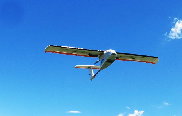
Now, I will introduce the details of Skywalker X6 with upgraded version. The cabin in the fuselage is bigger and layment plywood installed. By this way, it's more convenient to install electric appliance and it's really good to fly! Some customer have tested in this aircrafts successfully!

3689706495?profile=original

3689706517?profile=original

3689706595?profile=original

3689706616?profile=original

3689706540?profile=original

Characteristics

  • Adopted EPO material, light and sturdy.
  • Large capacity cabin, reasonable area distribution,such as layment plywood. 
  • Stable and flexible flying.
  • Module design, disassemble and assemble easily and conveniently.
  • Special winglet design, small resistance, long range, precise operation.


Specifications

  • Wingspan:1500mm
  • Fuselage length:650mm
  • Wing area:60dm2
  • Flying weight:1800-2000g


Recommended Cofiguration

  • Motor:2816KV980
  • ESC:60A
  • Servo:17g*2pcs
  • Propeller:9*5F
  • Battery:4S 4000mah
  • Radio:3CH

If you are interested in Skywalker X6 upgraded version, you can contact with me. 

Welcome to your review !!! I will reply to your question a.s.a.p. 

Thank you!

Read more…

plmaindiag.png?width=520

PingLocust is a Remote Control System based on 3G, 4G, or higher Internet Data Systems and is implemented on mobile devices using the Android Operating System. This results in a simple, straightforward, plug-for-plug replacement of conventional RC(Radio Control) systems and at the same time, provide instant additional functionality like enhanced range and reliability, digital real-time video, GPS tracking, telemetry, etc.

Video: Drone 20000 km max theoretical range

Rise of AI in Drones

Since PingLocust is Android-based,higher levels of functionality like machine vision functions, enhanced autonomy, subject recognition and tracking, virtual tourism, coordinated flying, etc. are easily possible as future enhancements.

PingLocust has 3 main components:
1) Controller App which serves as the RC transmitter
2) Slave App which serves as the RC receiver
3) Slave Whitebox which provides the wired interface between the Slave App and the servos (in the case of a ground/water RC vehicle) or low-level flight controller (in the case of a UAV/quadcopter/multicopter)

Features:
-Enhanced Range (Maximum theoretical range > 20,000 kilometers or 12,427 miles)
-Digital live Video Feed and recording
-Up to 12 proportional digital channels
-Up to 6 telemetry digital channels (for special versions of Whitebox)
-Wireless operation
-Enhanced signal reliability
-Live GPS data reception and recording
-Location and orientation can be displayed on Normal or Satellite Maps
-Speech warnings on Controller
-Channel Controls customization (exponential, variable rates, etc.)

plcont01.png?width=520Controller Screenshot

plslave01.png?width=520Slave Screenshot

whiteboxpic1.jpg?width=520Whitebox pic

Future Features

Since PingLocust is Android-based, enhancements in the areas of safety, autonomy, and accessibility is easier to implement. The following is a list of possible future enhancements:


-USB joystick controller support - emulating a conventional RC 2-stick controller
-Altitude hold and GPS lock for easier hovering
-More accurate hover and tracking using optical flow and other visual technologies
-Point-to-point autonomous GPS navigation
-Collision Avoidance
-Human subject recognition and tracking
-Gesture control
-Facial recognition
-Full autonomy using Artificial Intelligence (AI)
-Integration into Android Wear and other devices
-Voice control
-3D geo-fencing
-Object recognition and tracking
-Full internet integration (Virtual Tourism, remote camera hire, non-local package delivery, etc.)
-Automatic autonomous re-charging
-Coordinated flying across multiple slave/drone units
-Autonomous automatic deploy and retrieve
-Automated construction and assembly applications

PingLocust Main Page: http://preflightsim.com/plmain.html

For installing and using PingLocust apps (free versions available for evaluation): http://preflightsim.com/plinstalluse.html

PingLocust Whitebox: http://preflightsim.com/plwhiteb.html

Read more…

9e3f098c10845026ff800fb5147e46c153b06b32_1_375x500.jpg

3DroneMapping has been testing a PPK system for the past year to integrate into our daily workflow. The point of PPK (or Post Processing Kinematic) is not just to improve internal photogrammetric model orientations, but also is general recognised as a way of undertaking full scale surveys at the same accuracy but without having to place time consuming ground control points. 3DroneMapping setup a calibration site to test the claims made by the manufacturers and ultimately for our own quality assurance that what we publish is indeed right the first and only time.

Ground control points traditionally have become a sore topic with RPAS aerial surveyors as they take time to construct, survey and verify. These points are needed in a much greater density than tradition aerial survey methods, due to the non metric cameras often used in RPAS. Locations where the terrain changes rapidly, homogenous surfaces, and densely vegetated areas all require a higher density of control points to assist the photogrammetric software to locate accurate ties points and stop the model from deviating. Undertaking a photogrammetric survey without control, can lead to disastrous results, as outlined in a previous article, “GROUND CONTROL VS NO CONTROL”

There are a number of issues with placing and surveying control points. The obvious one being that another piece of survey equipment is needed to accurately record the positions. This comes at a great cost as survey grade GPS systems can run into tens of thousands of dollars. Then the areas for the control need to be identified. These areas are often located at the fringes of the site to be surveyed as well as in the center. This means that the site needs to be traversed (often on foot) to place marks and survey them. In some cases it can take a few days to complete the marking for fairly small sites due to the terrain, vegetation, etc. Control points are also not permanent. They often go missing due to weather, theft for vandalism and cause problem for the surveyor back in the office when the surveyed points are not visible on the imagery.

Another problem with using control only for surveys using low level photogrammetry is that the consumer grade cameras used are not metric and are prone to distortion. While control can eliminate this to an extent, it is the areas between the control points that often are forced to fit alignment. This can lead to errors especially regarding heights.

Emlid has produced and excellent L1 only receiver that is sure to revolutionise the Small Unmanned Aircraft photogrammetry sector. Coupled to a decent camera with a good lense and sync cable, the setup allows you to undertake surveys to mean accuracies of less than 10cm. All that is required is a base and a rover (2 devices) that log the data for you in an easy to operate webviewer. No need for external communication radios, or fancy antennas, only a steady 5v supply like a battery bank.

PPK is setup to have an accurate onboard GPS system that records a high frequency measurement tracklog of an RPAS flight. The system notes every time the camera takes an image and logs it. Another GPS is setup on the ground to record satellite information during the flight. Using a fork of RTKLib, Emlid has developed their own flavour of this powerful piece of software that takes into consideration each time the shutter is trigger and records the position of that event. The timing of such an event is crucial, as a few milliseconds delay can translate to a few meters when operating at speed. The software compares the relative satellite positions between the devices, resulting are very accurate coordinates for each image captured.

The photogrammetric model generated from using PPK enhanced images gives a much more consistent and accurate rendering of the terrain. Tie points have a much greater certainty of intersection, speeding up the matching processes. This reduction in uncertainty means less resources are required, leaving an opportunity to increase the density of other processes like point cloud generation, geometrically verified matching, etc.

Trials for PPK testing for 3DroneMapping began 3 weeks ago with a test calibration site. Over 200 tradition ground control points were surveyed over a 780ha site, some of which were placed in very challenging positions that like close to tall structures, under power lines, close to dense vegetation and visibly homogeneous surfaces. The control points were placed over 18 months and maintained. The site was flown over a 3 week period with a number of flights and post production methods to determine the optimum settings and processing requirements. At the end, the most consistent and repeatable results were chosen for the optimised settings for the end survey requirements and RPAS setup.

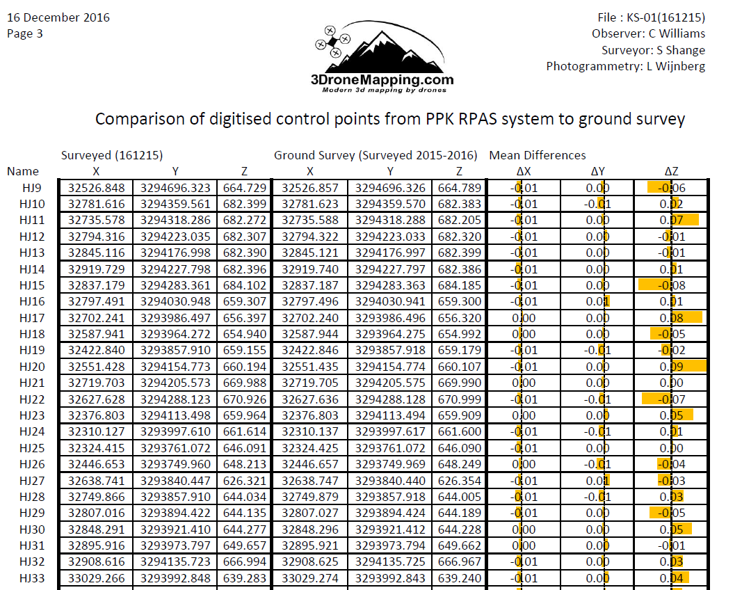
Control points were digitised from resulting point clouds and orthophotos and compared to the previously surveyed. These positions showed almost no difference to the control as published. Areas that have previously been a problem for photogrammetry showed up even and consistent between surveys when drawing profiles or cross sections. The 200 control points varied only a few centimeters over the entire site giving a very accurate and tight model.

The final fieldbook and comparison for the survey can be found here:
As a brief synopsis of the results, the maximum deviation of points was no more than 0.09m in all axis. This is an incredible result given the fact that the average pixel size of the resulting imagery was 0.045m. It is interesting to note that the average mean error in all axes is 0.00m! But this is meaningless as it is an average across the field. The maximum deviation measured between session as a profile or cross section indicated almost no shift at all, meaning that the data is consistent between sessions. This is close to impossible under normal operations with ground control points.

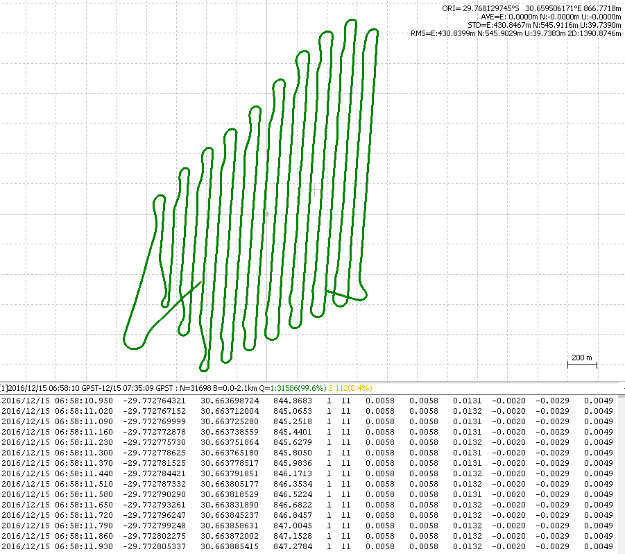
The aircraft used was a fixed wing RPAS carrying a Sony camera with fixed focal lense A total of 836 images were collected at 800ft AGL, with a 68% side and overlap. The test area is 780ha big and takes 45-55 min to fly at an average speed of 19m/s. The Reach was recording data at 14hz, GPS only. The ground survey completed with Leica GPS1200 checked measurements to 0.02m horizontal and 0.03m vertical accuracy with all points checked and meaned

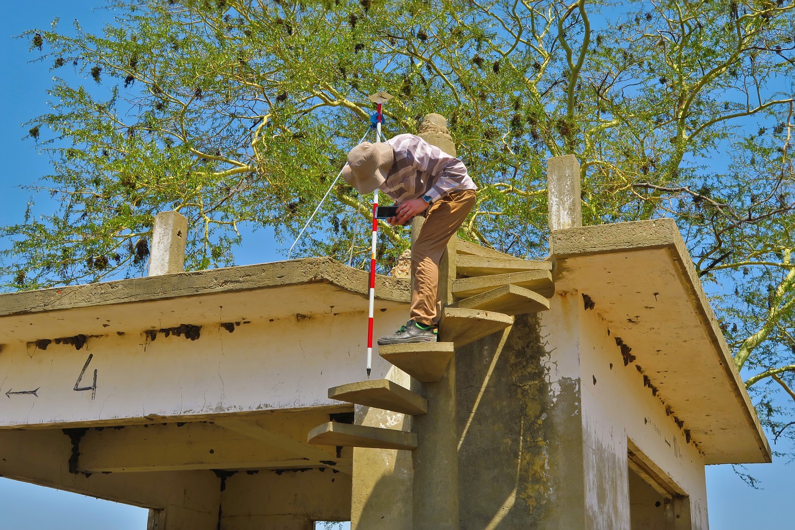
  • PPK setup using Sony A6000 camera, 20mm lense, EMLID Reach with flash sync, Tallysman TW4721, ReachView beta v2.1.5
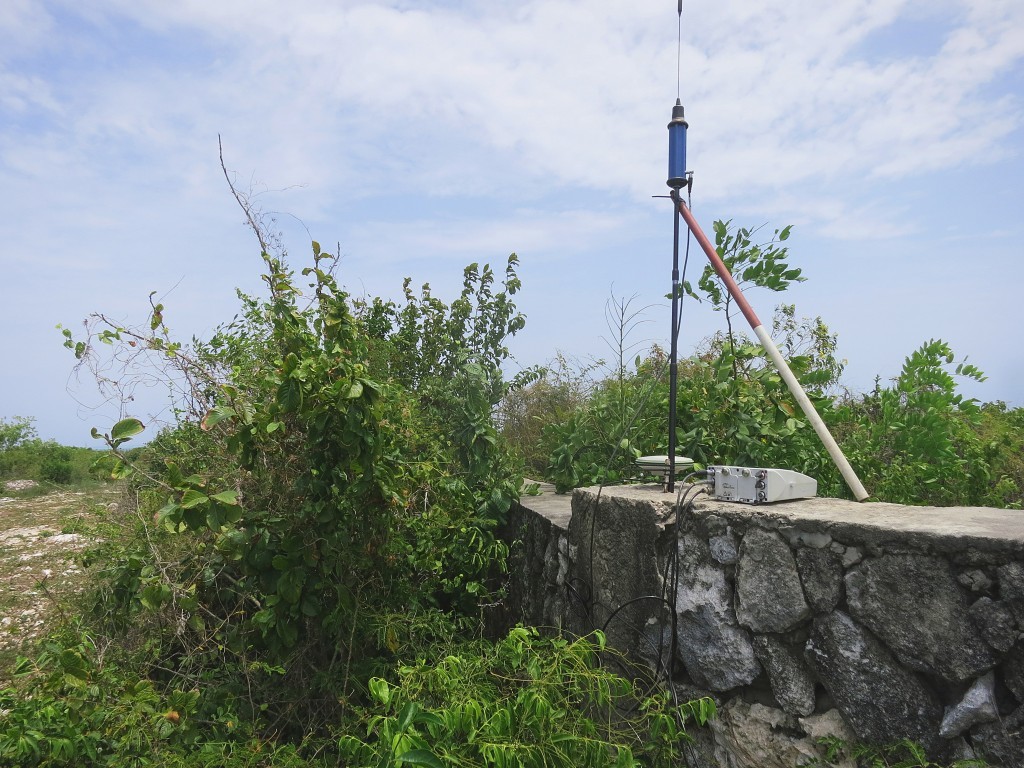
  • PPK base running EMLID Reach, TW2410, ReachView beta v2.1.5
  • PPK post processed in RTKPOST ver2.4.3_Emlid_b26
  • Photogrammetry done in Pix4Dmapper Pro Ver 3.0.17
  • Orthophoto resolution 0.043m, point cloud resolution 47.1 points per m³
  • Comparison digitised in ArcGIS V10.0
  • EPSG:2054. Hartebeesthoek94 / Lo31

What this all translates to is that surveys can now be undertaken with even less time spent in the field and can result in even more accurate and consistent data. But should you not place control at all? This is a bad survey practice as you are depending on only 1 set of data measurements. As a caution, we would still place only a few control points as a quality assurance test to prove to yourself and others about the precision of the data generated.
But you do not need to buy or hire a GPS for this as the very same Emlid Reach in the aircraft can be used to survey those control points just as accurately!

9d3de5c1f84b03caee814d4c1e37235c3f337361.jpg

Read more…

modesw.jpg

IMG_20161217_130502.jpg

This is the first version of my mode switch holder for the Taranis. It fits the Hobbyking / X-Rock mode switch. It mounts in place of the left slider (I pretty much never use the sliders). A hole to route the cables is included in the design. This version still is a little bit close to switch E. Still doing some fine tuning.

Published under CC-BY-SA 3.0
Download at http://stefan.gofferje.net/downloads/file/31-taranis-mode-switch-holder

Read more…
3D Robotics

DIY Drones at 82,000 members

3689706682?profile=original

It's customary and traditional that we celebrate the addition of every 1,000 new members here and share the traffic stats. We've now passed 82,000 members!

Thanks as always to all the community members who make this growth possible, and especially to the administrators and moderators who approve new members, blog posts and otherwise respond to questions and keep the website running smoothly.

Read more…
Moderator

3689706733?profile=original

"The drone market today can be described as a melting pot of different technologies, where combinations of hard- and software components and service features are provided to the end user. In order to create sustainable success in this extremely fast moving market it is essential to maintain strategic partnerships or invest in a solid UAV portfolio. This is nothing new and as we showed in our recent publication this is a process that started quite a while ago, long before anyone thought about drones to be the next big thing.

However, lately a few players have been extremely busy with engaging in new partnerships, looking for investment opportunities and acquisitions.

Currently, the commercial UAV market consists of three dominant players, namely DJI, Parrot SA and the Intel Corporation.

Parrot started creating professional solutions at a very early stage. The acquisition of Software manufacturer Pix4D (2012) and MicaSense (2014) were great strategic moves and paved the way to highly advanced end-to-end solutions. Although profit margins in the commercial UAV market were very small at this time, Parrot did invest heavily into their new strategy. Building a new market segment has never been easy (or cheap) and the low-cost competitors from Asia also apply a lot of pressure causing market deficits especially in the hobby/prosumer sector. Despite, the share of the drone sector within the Parrot Group increased from 38% (Q1 2016) to 54% (Q2 2016) due to this strategic move.

Whereas Parrot started three years earlier, Intel Capital started in 2014 to invest into the drone industry. Now, Intel Corp. chooses a pro-active approach and moves into the market by acquiring the missing pieces of the puzzle around their high-performance chip-sets. The Intel RealSense platform combines hardware and software in a way that enables cameras to process and understand images, and eventually providing “computer vision” to flying drones. Before acquiring the German drone manufacturer Ascending Technologies earlier this year, the two companies had already engaged in a close partnership to improve UAV sense and avoid systems. Intel’s biggest and certainly most game-changing move was the acquisition of the mobile vision processor company Movidius. This acquisition paves Intel’s way towards autonomous systems – not only for unmanned aerial vehicles.

Other chip manufacturers such as Qualcomm and Nvidia have recently copied Intel’s strategy, as they see the immense opportunities in becoming technology suppliers for the emerging drone industry.

The third key player and dominant market leader DJI also started a number of new partnerships this year. While Intel and Parrot grew their drone business through acquisitions, DJI now uses partners to expand their business portfolio (e.g. the infrared camera maker FLIR, surveying expert Leica Geosystems and micro ADS-B transponder manufacturer uAviniox). For their position this strategy makes a lot of sense since DJI has everything it needs to bring drones up in the air and as such, does not have to acquire the technology. Partnering can be an extremely quick way to grow a company, particularly in times of rapid change. Without implementing difficult and time-consuming internal changes DJI can expand the knowledge of different industry sectors, boost innovation and increase their market share.

Initially partnerships were heavy on hardware but the demand to deliver high-quality end-to-end products more quickly and at lower costs has become a fundamental part of the entire UAV industry."

https://www.droneii.com/drone-market-strategies

Read more…
3D Robotics

Measuring airspeed without an airspeed sensor

3689706664?profile=original

Interesting post from the FlightGear blog via Curtis Olson:

Motivation

Air France #447Air France #447

On June 1, 2009 Air France flight #447 disappeared over the Atlantic Ocean.  The subsequent investigation concluded “that the aircraft crashed after temporary inconsistencies between the airspeedmeasurements – likely due to the aircraft’s pitot tubes being obstructed by ice crystals – caused the autopilot to disconnect, after which the crew reacted incorrectly and ultimately caused the aircraft to enter an aerodynamic stall from which it did not recover.”  https://en.wikipedia.org/wiki/Air_France_Flight_447

This incident along with a wide variety of in-flight pitot tube problems across the aviation world have led the industry to be interested in so called “synthetic airspeed” sensors.  In other words, is it possible to estimate the aircraft’s airspeed by using a combination of other sensors and techniques when we are unable to directly measure airspeed with a pitot tube?

Basic Aerodynamics

Next, I need to say a quick word about basic aerodynamics with much hand waving.  If we fix the elevator position of an aircraft, fix the throttle position, and hold a level (or fixed) bank angle, the aircraft will typically respond with a slowly damped phugoid and eventually settle out at some ‘trimmed’ airspeed.

Phugoid8.png

If the current airspeed is faster than the trimmed airspeed, the aircraft will have a positive pitch up rate which will lead to a reduction in airspeed.  If the airspeed is slower than the trimmed airspeed, the aircraft will have a negative pitch rate which will lead to an acceleration.  https://en.wikipedia.org/wiki/Phugoid

The important point is that these variables are somehow all interrelated.  If you hold everything else fixed, there is a distinct relationship between airspeed and pitch rate, but this relationship is highly dependent on the current position of elevator, possibly throttle, and bank angle.

Measurement Variables and Sensors

In a small UAS under normal operating conditions, we can measure a variety of variables with fairly good accuracy.  The variables that I wish to consider for this synthetic airspeed experiment are: bank angle, throttle position, elevator position, pitch rate, and indicated airspeed.

We can conduct a flight and record a time history of all these variables.  We presume that they have some fixed relationship based on the physics and flight qualities of the specific aircraft in it’s current configuration.

It would be possible to imagine some well crafted physics based equation that expressed the true relationship between these variables …. but this is a quick afternoon hack and that would require too much time and too much thinking!

Radial Basis Functions

Enter radial basis functions.  You can read all about them here:  https://en.wikipedia.org/wiki/Radial_basis_function

From a practical perspective, I don’t really need to understand how radial basis functions work.  I can simply write a python script that imports the scipy.interpolate.Rbf module and just use it like a black box.  After that, I might be tempted to write a blog post, reference radial basis functions, link to wikipedia, and try to sound really smart!

Training the Interpolater

Step one is to dump the time history of these 5 selected variables into the Rbf module so it can do it’s magic.  There is a slight catch, however.  Internally the rbf module creates an x by x matrix where x is the number of samples you provide.   With just a few minutes of data you can quickly blow up all the memory on your PC.  As a work around I split the entire range of all the variables into bins of size n.  In this case I have 4 independent variables (bank angle, throttle position, elevator position, and pitch rate) which leads to an n x n x n x n matrix.  For dimensions in the range of 10-25 this is quite manageable.

Each element of the 4 dimensional matrix becomes a bin that holds he average airspeed for all the measurements that fall within that bin.  This matrix is sparse, so I can extract just the non-zero bins (where we have measurement data) and pass that to the Rbf module.  This accomplishes two nice results: (1) reduces the memory requirements to something that is manageable, and (2) averages out the individual noisy airspeed measurements.

Testing the Interpolater

Now comes the big moment!  In flight we can still sense bank angle, throttle position, elevator position, and pitch rate.  Can we feed these into the Rbf interpolater and get back out an accurate estimate of the airspeed?

Here is an example of one flight that shows this technique actually can produce some sensible results.  Would this be close enough (with some smoothing) to safely navigate an aircraft through the sky in the event of a pitot tube failure?  Could this be used to detect pitot tube failures?  Would this allow the pitot tube to be completely removed (after the interpolater is trained of course)?

Synthetic airspeed estimate versus measured airspeed. Zoom on one portion of the flight. synth_asi3-1024x524.jpgZoom in on another portion of the flight.

Source Code

The source code for this experimental afternoon hack can be found here (along with quite a bit of companion code to estimate aircraft attitude and winds via a variety of algorithms.)

https://github.com/AuraUAS/navigation/blob/master/scripts/synth_asi.py

Conclusions

This is the results of a quick afternoon experiment.  Hopefully I have showed that creating a useful synthetic airspeed sensor is possible.  There are many other (probably better) ways a synthetic air speed sensor could be derived and implemented.  Are there other important flight variables that should be considered?  How would you create an equation that models the physical relationship between these sensor variables?  What are your thoughts?

Read more…

Static thrust optimized EDFs

3689706719?profile=original

UAS Vision published an article on these EDFs optimized for static thrust.  Something I am constanly googling around for but never seem to find...

"The pan-European Neva Aerospace consortium, which is developing heavy-duty drones, industrial and commercial unmanned aerial systems (UAS) and vehicles (UAV) based on its patented distributed thrust concept, has released the first OEM electric turbofan (ETF) to the aerospace market. These ETFs are claimed to be between two and four times as efficient as existing, standard electric ducted fans (EDFs).

The Neva Athena ETFs are a world first and are the only ducted fans optimised for static thrust and VTOL/STOL.  A unique turbofan housing design further boosts the thrust without any compromise on weight saving.

The breakthrough technology of the Athena Series turbines will displace uncaged rotor blades in current commercial drone applications and will create exciting new possibilities for the development of the next generation of unmanned aerial systems.

Athena ETFs will be able to lift drones of more than 25kg with 10 turbofans across a surface of less than 1.5m diameter,  according to Neva engineers.

The Neva technology is scalable nearly infinitely and limited only by the energy density of batteries, the capabilities of controllers and, as these technologies advance, the imagination and audacity of drone designers. Other models in the Athena Series are under final development and testing."

Full article:

http://www.uasvision.com/2016/12/14/neva-releases-oem-electric-turbo-fans-optimised-for-vtol-and-stol-commercial-uas/#more-47294

Neva website:

https://www.neva-aero.com/index.php/oem/athena-series

Read more…

3689706641?profile=original

Sky-Futures cloud-based drone inspection visualization and reporting software squarely targets the asset inspection sector, but will it be broadly adopted? 

THE FACTS:

No one questions whether the founders of Sky-Futures know what they are doing.  When it comes to drone inspections they have “been there, done that.”  You can read about their history and where they are going in The importance of industrial experience when enabling enterprise with drone capabilities, a post written by co-founder & CEO James Harrison. I won’t repeat all the facts, just the salient one. 

When they started in June 2009, they assessed different markets, sizing them and then trying to forecast how they would look in 5 and 10 years’ time. They chose the drone inspection service market in the oil and gas (O&G) industry because of its highly inaccessible, highly hazardous and critical infrastructure, and its focus on safety and regulation. They succeeded in understanding the very specific needs of the industrial inspections market, got steady revenue stream, and have now turned to offering a software-as-a-service (SaaS) product as another generator of their future value. Their product is called ExpanseSM and is designed and built for drone-based operations management, inspections, data analysis, and reporting.

WHAT’S COOL AND WHAT’S NOT

There’s a lot to like about Expanse.  For one, it has an asset-centric view of the world—not an inspection-centric one.  In the inspection-centric view, reports provide little context for consumers of the information on the “who, what, where, and when” of problems. By taking the asset-centric view, Expanse starts with the “where” (a specific structure) and allows users to navigate to the areas of an asset that’s important to them—the “what,” like a rusty pipe or misaligned cell tower antenna. Everyone reading inspection reports has a different need (not everybody has responsibility for the integrity of pipes), so the software provides context.

Continue reading here:  http://droneanalyst.com/2016/12/15/is-sky-futures-expanse-drone-inspection-software-good-for-all/

Read more…

UgCS 2.10 Has Been Released

3689706702?profile=original

SPH Engineering’s latest update to UgCS mission planning software for drones brings improvements to features, user interface ergonomics and a new affordable licence type for UAV professionals.


Added support for PX4, DJI Matrice 600 and DJI A3 autopilot, expanding the already wide base of UgCS supported drones.

The UgCS version 2.10 features many changes, one of the biggest is automatic route calculation in the background as you draw it. Once the route is created - just upload it to the drone and it is ready to fly.


To ease route planning, the option to clone or move whole route as single element is added. It is also possible to select multiple parts of a route and edit their common parameters in batch.


Starting from version 2.10 there will be four UgCS licences available: UgCS OPEN, UgCS ONE, UgCS PRO and UgCS ENTERPRISE. All users who bought UgCS PRO before version 2.10 will be transferred to UgCS ENTERPRISE after update to version 2.10.


New UgCS PRO is created based on consultations with UAV professionals, to equip pro-users with a complete mission planner and ground control software to enable advanced mission management. Amongst basic UgCS features new UgCS PRO enables KML and DEM import, import of Geo-referenced images and NFZ management. Also three simultaneous connections to UgCS server are allowed from clients thus lowering cost to start getting benefits from UgCS SDK (software development kit) and custom integrations with 3rd party systems for those who want to create more complex UAV control environments. Last but not least - all that for an affordable price.


To enable more ergonomic mission planning, user interface (UI) has been redesigned. UgCS event window is divided in two separate windows: one related to route events and second related to UAV events. Thus operator does not loose important drone status and warning messages between technical information concerning route setup and calculation.


Other significant improvements:

  • Joystick calibration support,
  • Changed vehicle profile sorting – profiles for recently added vehicles to mission are at the top,
  • Support for Parrot Sequoia camera,
  • Redesigned telemetry export for improved ease of use.


Full list of updates can be seen in UgCS version 2.10 release notes:
https://www.ugcs.com/en/page/download

About UgCS

UgCS is a software developed by SPH Engineering for central management of all types and manufacturers of unmanned vehicles, enabling to control one or a fleet of drones on a single mission in multi operator mode and multi-platform environments. Ease of integration and adding support for new vehicles or payloads is achieved by modular architecture of UgCS. SPH Engineering offers unmanned systems integration services: building, acquiring and consulting on selection of airframes, autopilots, payloads for particular application and performing proof of concept projects and software development. More: www.ugcs.com

Media contact: Janis Kuze, Sales Director

E-mail: ugcs@ugcs.com, Phone: +371 2545 3422

Resources:

Read more…

Intel edison Yocto image build step as of 12/13/2016

3689706420?profile=original

I spent quite a few hours in figuring out a way to build Yocto image for edison from its recipes. Here is the steps in building an image successfully.

1. download recipes from http://iotdk.intel.com/src/3.5/edison/iot-devkit-yp-poky-edison-20160606.zip

2. unzip iot-devkit-yp-poky-edison-20160606.zip

3. cd iot-devkit-yp-poky-edison-20160606/poky/

4. source oe-init-build-env ../build_edison/

5. sudo apt-get install build-essential git diffstat gawk chrpath texinfo libtool gcc-multilib

6. sudo apt-get install libsdl1.2-dev

7. download  http://git.yoctoproject.org/cgit.cgi/meta-java/commit/recipes-core/icedtea,upzip and replace all checksums in /poky/meta-java/recipes-core/icedtea/icedtea7-native_2.1.3.bb with the value in downloaded file. Then, replace all patches in /poky/meta-java/recipes-core/icedtea/openjdk7-03b147 with the patches from downloaded file.

8. comment out the following two lines 

IMAGE_INSTALL += "iotkit-comm-js" 
 IMAGE_INSTALL += "iotkit-comm-c-dev"


from 
poky/meta-intel-edison-distro/recipes-core/images/edison-image.bb

9. edit ../poky/meta-intel-edison/utils/flash/postBuild.sh line 9 to build_dir=$top_repo_dir/build/../build_edison

10. ../poky/meta-intel-edison/utils/flash/postBuild.sh

9. zip -r toFlash.zip toFlash

Read more…

Today, Velodyne is announcing a "a groundbreaking design for a solid-state lidar sensor that can deliver a subsystem cost of under $50 U.S. when sold in high-volume manufacturing scale.

Before:

3689706288?profile=original

After ?:

3689706356?profile=original

What you're seeing is the GaN integrated circuit that forms the heart of the solution that Velodyne is proposing. This is the chip that does the transmit function.

http://spectrum.ieee.org/cars-that-think/transportation/sensors/velodyne-announces-breakthrough-in-solid-state-lidar-design

Read more…
T3

3689706405?profile=original

3689706373?profile=original

Revising the Airspace Model for commercial drone integration

This paper is also containing superior solution exitisng Amazon's patent applications (even if those are also often based on prior art, please contact me to complete a list).

The paper also contains discussion on practical aspects of ground avoidance in US airspace.

Read more…
3D Robotics

WebODM, a easy workflow app for Open Drone Map

3689706187?profile=original

From Hackaday:

WebODM allows you to create georeferenced maps, point clouds and textured 3D models from your drone footage. The software is really an integration and workflow manager for Open Drone Map, which does most of the heavy lifting.

Getting started with WebODM or Open Drone Map is simple since they provide preconfigured Docker images. You don’t have to worry about assembling a bunch of dependencies to make everything work. There are other mapping applications in use, too. You can see a comparison of five popular choices in the video below. WebODM isn’t complete yet, but they intend to include mission planning and integration with mobile apps.

Read more…

Andruav Web GCS is the new Andruav arm that enables UAV pilots to remotely control their drones. Andruav has been known for its ability to track multiple drones, multiple board types, and provide FPV capability. Now withAndruav Web you can control your quad, rover, plane by mouse clicks from your laptop.

DIY @ Home Flying

Thanks to Drone-SITL  you can reliably and safely test Andruav and its capabilities using a laptop and an Android mobile. Drone-STIL is a software-in-the-loop that simulate different vehicles run Ardupilot firmwares, the main andantage when it come to Andruav is that drone-stil simulates the input sensors, and physics model, but when it comes to calculations, path planning, modes ...etc. it uses the very same code that runs on your drone.

Drone-STIL may be not enough for practicing your flight skills, but it is enough to test and train your self on mission planning, using Tower APP & MAVLINK protocol. WHY ? because what happens here is that your commands are being processed with the very same code that runs on physical boards, the simulated sensors and motors are not the concern here, and not affecting any results in that area. So if you have a working tuned drone, so what Andruav can do with Drone-STIL will do it exactly with your own drone. So this is a training play ground that you can use to verify Andruav true capabilities.

Using Drone-STIL with Andruav

1- You need to install Drone-SITL on your machine.

2- You need to install MavProxy, this is the proxy that will be used to connect Andruav to Drone-SITL.
3- If you have everything installed correctly you should be able to run drone-sitl as in the following command:

                           sudo dronekit-sitl copter --home=-35.3632161,149.165229,0,0 --model=quad
4- Now you need to run mavproxy to connect your dronekit with Andruav. but first you need to know the IP address of Andruav Drone Mobile. each time you connect your mobile to your local wifi network it will get a new IP, so each time you need to get this new IP and connect to it.
Another solution is to use your wifi router to set a fixed IP address for your mobile by attaching a fixed IP address to the MAC address of your phone.

Assuming your mobile ip address is 192.168.1.5 then you need to run MAVProxy:
                          sudo mavproxy.py --master=tcp:127.0.0.1:5760 --out=udpout:192.168.1.5:14555


Now all you need to do is to open Andruav in Drone Mode, go to FCB screen, and choose a UDP connection either native of via 3DR Services, and that's it.

3689706261?profile=original

Now Andruav will behave exactly as if it were connected to a real drone, now you can test your telemetry features easily and safely.

What is in the Video ?

The video is created using two Android mobiles running Andruav Drone-Mode, each mobile is connected to a Drone-STIL instance, one of them is for the quad, and the other is for Rover. 

In the video you can see Andruav automatically distinguishes between different vehicles, and modes that each vehicle can take.

Using double-click a destination appears where you can make vehicles goes to it -when they are in Guided mode-.

Also you can use Andruav Fence Editor, you can easily open it from Andruav Web to open in the same location, you can define fences in different shapes. Fences are stored in Andruav global database, and whenever you start any Drone your own fences will be downloaded automatically - you can delete them from web-.

Fences can be soft as in video, or hard that trigger RTL when a vehicle reaches it.

You can control YAW, Altitude, Capture Images from Mobile or Drone Camera.

You can stream HD Video from Drone Mobile.

Please try it yourself ... you can produce your own Andruav video same like the one above.

Have Fun :)


Read more…

Hi guys, check out the second episode of our show with Grant Imahara from Mythbusters sponsored by Mouser and Intel. 

In this episode we go more in-depth into the electronics and systems developed specifically for this project. You will see our proprietary mechanical design for centering the drone and placing it on top of the charging pads.  

This project represents one of many uses for our remote drone deployment platform in the cloud - Global ARC. 

Interested to hear your thoughts. 

Read more…
3D Robotics

New RTF VTOL plane from Horizon

Out now for $250. Anybody have any experience if this can be converted into autonomy with a Pixhawk or similar?

Overview

VTOL (Vertical Takeoff and Landing) RC models are usually a mixed bag when it comes to performance. If they are stable, their speed and agility is often lackluster. If they are nimble, pilots have to work harder to transition between hovering and airplane flight. The Convergence™ VTOL park flyer changes all that. Its unique design and exclusive flight control software give you the best of both agility and stability while making the transition between multirotor and airplane flight so smooth and predictable, you will feel right at home your first time on the sticks.

Sleek and Simple

Unlike complex VTOL aircraft that rotate the entire wing and require as many as four motors to achieve vertical and forward flight, the Convergence™ park flyer uses a simple, yet sleek, delta-wing design with three brushless motors - two rotating motors on the wing and a fixed-position motor in the tail.

In multirotor flight the wing-mounted motors rotate up into the vertical position to provide lift and flight control along with the motor in the tail. In airplane flight, the wing-mounted motors rotate down into the horizontal position and the model's elevons take over pitch and bank control. Yaw control in airplane flight is provided by differential thrust from the wing-mounted motors.

Exclusive Flight Control Software Makes it Easy

At the heart of it all is flight control software that has been expertly tuned by designer, Mike McConville, so almost any RC pilot can experience the fun of VTOL flight.

Automated Transition

Making the transition between multirotor and airplane flight is as simple as flipping a switch. The flight controller will smoothly rotate the two wing-mounted motors into the correct flight attitude and activate the rear motor as needed.

Stability and Acro Flight Modes

These two flight modes give you a wide range of performance for every phase of flight.

  • Stability Mode
    • In multirotor flight, Stability Mode will limit pitch and bank angles and work to keep the model level when you release the sticks. This allows you to take off and land like a pro, even if you've never flown a multirotor before. In airplane flight, it will limit pitch and bank angles and automatically return the wings to level when the sticks are released.
    • Stability Mode automatically engages during the transition between multirotor and airplane flight. It seamlessly maintains self-leveling and angle limits from one phase of flight to the other, making this the easiest RC VTOL experience you will find anywhere.
  • Acro Mode
    • In Acro Mode there are no angle limits or self-leveling in any phase of flight. During multirotor flight, the model will behave like a conventional multirotor that pitches and banks in whatever direction you want it to fly. It can flip and roll like other multirotors, too.
    • In airplane flight, Acro Mode lets you perform a wide range of aerobatic maneuvers. And because you have the forward thrust of two brushless motors working for you, there is plenty of speed and power to spare. You can even use the differential thrust of the motors to perform unique spinning and tumbling maneuvers.
Read more…

y8dEp9lIg80aOE7BuzV5S-unyxfG8DV6FSoBx17YuD2mbOaltI2Y6NCwWVo1ZgR2d-00HaTIOwusL6kz1A6lduHUihjlqGucKea_dLcwzSX-B1a7QmUoDmjzSv0OqUuksN1BvsvQ?width=750

DroneMapper is very pleased to announce that RAPID for DJI is available for download and testing on limited imagery data sets at no cost to the user. RAPID will provide scaled DEMs and orthomosaics using up to 75 images for a scene. Results are available in near real time using modest computing hardware.

The download link can be found here: DroneMapper Software & Downloads | Drone Mapper Imagery Processing

Three WINDOWS 10 (64bit) applications with different features and functionality are offered and are summarized below:

• RAPID for DJI (Free): Allows input of up to 75 geo-tagged JPEG images of 12 Mpixel format or greater. RAPID will produce a preview orthomosaic, a DEM scaled at X8 of imagery native resolution and an orthomosaic scaled at X4 as output products in GeoTiff format. RAPID for DJI is limited to DJI platforms and sensors.

• REMOTE (Licensed): For larger mapping areas, this module allows input of up to 400 geo-tagged JPEG images of 12 Mpixel format or greater. REMOTE will produce a preview orthomosaic, a DEM scaled at X8 or X4 of imagery native resolution and an orthomosaic scaled at X4 or X2 as output products in GeoTiff format.

• REMOTE EXPERT (Licensed): This module provides full photogrammetric functionality and allows input of up to 1000 geo-tagged JPEG images of 12 Mpixel format or greater. REMOTE EXPERT produces a preview orthomosaic, a DEM scaled at X8, X4 or X2 of imagery native resolution (user selectable) and an orthomosaic scaled at X4, X2 or native resolution (user selectable) as output products in GeoTiff format. This module also will perform processing using ground control points (GCPs). This feature requires imagery pre-processing using the included GCP Tool. The module will generate a 64-bit point cloud of the results in ASCII PLY/XYZ format should the user select that feature.

Feature/Function Benefits
• Orthomosaic preview – facilitates review of acceptable imagery collection at the site, prior to equipment pack-up, by generating the preview in near real time. In many cases the preview will help identify holes in coverage, issues with image geo-tagging and poor quality imagery (blur and other imagery artifacts that hamper proper processing) before you leave the scene.
• Linear and area measurements for overlap verification and scene coverage.
• Selectable scaling of the DEM appropriate for the project requirements. If 1-2’ contours and/or volumetrics are required, then a X8 DEM may be suitable for the quickest turn around and acceptable accuracy. If finer detail is desired, then X4 and X2 DEMs are selected at the expense of processing time.
• Selectable scaling and blending of the orthomosaic for scene feature identification and production of a visually pleasing (minimal to no seamlines) scene.
• DEM and orthomosaic sub-pixel root mean square error (RMSE) of GCPs in horizontal and vertical - facilitates accurate planimetric and 3-D measurements.
• 64-bit point cloud provided for feature classification, editing and DTM generation.
• Robust processing algorithms tolerant of minimal imagery overlap. Allows user to close the loop on operations platform, camera/lens and mission planner to minimize overlaps for high efficiency collects over larger areas, quick processing turnaround times and high quality output.

Please review the operating instructions, run the application on your data sets and provide us feedback on its operation and utility. Should you need additional functionality for larger data sets please contact us for more details on REMOTE and REMOTE EXPERT.

Happy Holidays,
the DroneMapper Team

More information: https://dronemapper.com

Help and Support: https://dronemapper.freshdesk.com/support/home

Read more…